

Page 1
EDFP10C*A EDFP14C*A EDFP17C*A EDFP17DSC*A EDFP17RAC*A EDFP17SLC*A
Installation/Care/Use Manual
Non-Refrigerated Fountains with FLEXI-GUARD
23
24
EDFP10C, EDFP14C EDFP17C, EDFP17DSC
Installer
To assure you install this model easily and correctly, PLEASE READ THESE SIMPLE
INSTRUCTIONS BEFORE STARTING THE INSTALLATION. CHECK YOUR INSTALLATION FOR COMPLIANCE WITH PLUMBING, ELECTRICAL AND OTHER APPLICABLE
CODES. After installation, leave these instructions inside the fountain for future reference.
®
SEE FIG. 3
OR 4
SEE FIG. 7
25
IMPORTANT
ALL SERVICE TO BE PERFORMED BY AN AUTHORIZED SERVICE PERSON
IMPORTANT! INSTALLER PLEASE NOTE.
THE GROUNDING OF ELECTRICAL EQUIPMENT SUCH AS TELEPHONE, COMPUTERS, ETC. TO WATER LINES
IS A COMMON PROCEDURE. THIS GROUNDING MAY BE IN THE BUILDING OR MAY OCCUR AWAY FROM THE
BUILDING. THIS GROUNDING CAN CAUSE ELECTRICAL FEEDBACK INTO A FOUNTAIN, CREATING AN ELECTROLYSIS WHICH CAUSES A METALLIC TASTE OR AN INCREASE IN THE METAL CONTENT OF THE WATER.
THIS CONDITION IS AVOIDABLE BY USING THE PROPER MATERIALS AS INDICATED. ANY DRAIN FITTINGS
PROVIDED BY THE INSTALLER SHOULD BE MADE OF PLASTIC TO ELECTRICALLY ISOLATE THE FOUNTAIN
FROM THE BUILDING PLUMBING SYSTEM.
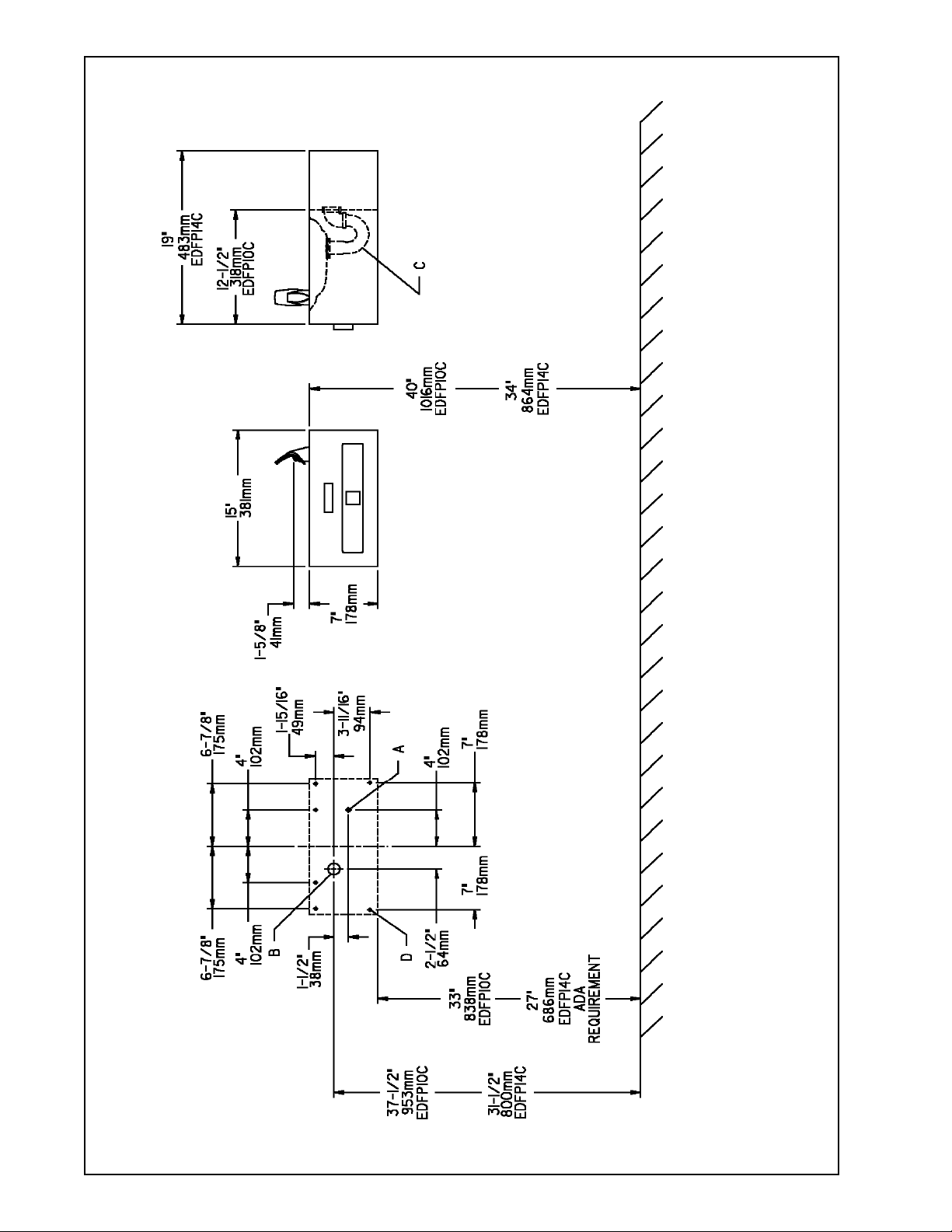
1. Wall should already be framed for the fountain using the positioning dimensions shown in Figures 1 or 2. Shown dimensions pertain to
installation location (framing must support up to 150 lbs. weight). These dimensions are required for compliance with ANSI Standard
A117.1/ADA requirements.
2. Install rough-in plumbing as shown in Figures 1 or 2. Waste line should extend a minimum of 2" (51mm) through the back panel.
Connecting lines to be unplated copper and thoroughly flushed to remove all foreign matter before connection to fountain. Run the
supply water inlet line through the back panel. Install a service stop (not provided). Turn on supply water and flush thoroughly.
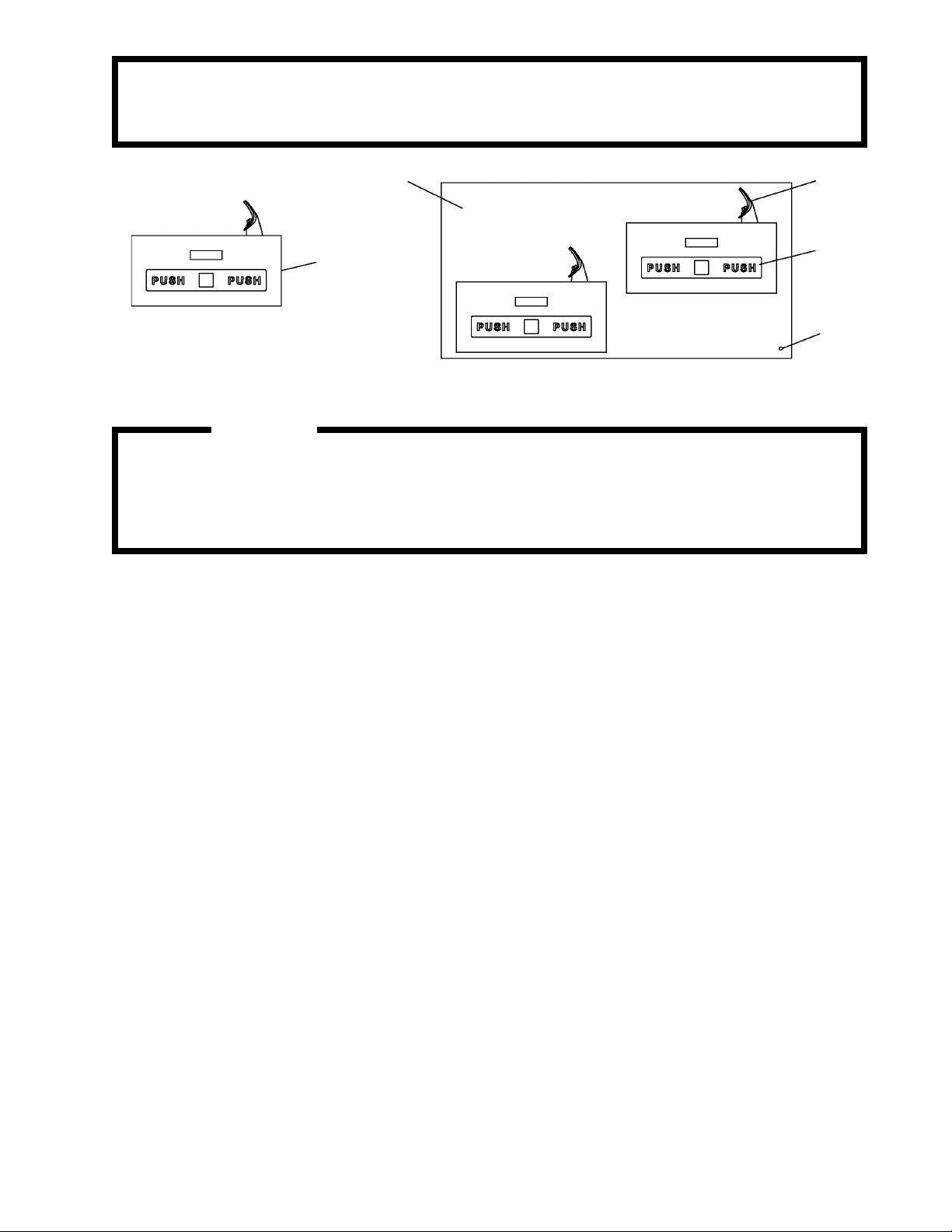
3. MODELS EDFP10C, EDFP14C: Secure the fountain to the wall using (6) bolts and washers (not provided). Tighten securely.
MODEL EDFP17C: Install the fountain to the back panel using (2) bolts and washers (not provided) per each fountain. Next secure
the fountain bodies and back panel to the wall using (4) bolts and washers (not provided) per each fountain. Now secure lower right
hand corner of back panel using a #8 x 1.50" long bolt (Item 25). Tighten securely.
4. Remove elbow from end of p-trap and attach it to drain tube. Reattach elbow to p-trap and cut waste tube to required length using
plumbing hardware and trap as a guide.
5. Make water supply connections from service stop to the 3/8" O.D. unplated copper tube coming out of the strainer. Turn on water
supply and check for leaks. Newly installed water supply line should be insulated after leak check is completed. DO NOT SOLDER
TUBES INSERTED INTO THE STRAINER AS DAMAGE TO THE O-RINGS MAY RESULT.
6. These products are designed to operate on 20-105 PSIG supply line pressure. If inlet pressure is above 105 PSIG, a pressure regulator
must be installed in the supply line. Any damage caused by reason of connecting these products to supply line pressures lower than 20
PSIG or higher than 105 PSIG is not covered by warranty.
7. Check stream height from bubbler. Stream height is factory set at 35 PSI. If supply pressure varies greatly from this, turn adjustment
screw on the regulator (Item 7). Clockwise adjustment will raise stream height and counter-clockwise will lower stream height. For best
adjustment stream should hit basin approximately 6-1/2" (165mm) from bubbler.
1. Orifice Assy: Mineral deposits on orifice can cause water flow to spurt or not regulate. Mineral deposits may be removed from orifice
with a small round file not over 1/8" diameter or a small diameter wire. CAUTION: Do not file or cut orifice materials.
2. Actuation of Quick Connect Water Fittings: Cooler is provided with lead-free connectors which utilize an o-ring water seal. To remove
tubing from the fitting, relieve water pressure, push in on the gray collar while pulling on the tubing (See Figure 6). To insert tubing,
push tube straight into the fitting until it reaches a positive stop, approximately 3/4".
INSTALLATION INSTRUCTIONS
TROUBLE SHOOTING AND MAINTENANCE
97105C (Rev. E - 09/03)
Page 2
EDFP10C*A EDFP14C*A EDFP17C*A EDFP17DSC*A EDFP17RAC*A EDFP17SLC*A
EDFP10C, EDFP14C
FIG. 1
FINISHED FLOOR
C = 1-1/4" TRAP FURNISHED
D = 1/4" (6mm) DIA. HOLES FOR SECURING FOUNTAIN TO WALL
97105C (Rev. E - 09/03)
PAGE 2
LEGEND
A = RECOMMENDED WATER SUPPLY LOCATION 3/8 O.D. UNPLATED COPPER
TUBE CONNECT STUBBED 1" (25mm) FROM WALL SHUT OFF BY OTHERS
B = MODEL EDFP10C: RECOMMENDED LOCATION FOR WASTE OUTLET 1-1/4"
O.D. DRAIN STUBBED 1-3/8" (35mm) FROM THE WALL
MODEL EDFP14C: RECOMMENDED LOCATION FOR WASTE OUTLET 1-1/4"
O.D. DRAIN STUBBED 6-5/8" (168mm) FROM THE WALL
Page 3

PAGE 3
EDFP17C SHOWN. FOR EDFP17RAC, LOWER FOUNTAIN
IS ON RIGHT AND UPPER FOUNTAIN IS LEFT.
EDFP10C*A EDFP14C*A EDFP17C*A EDFP17DSC*A EDFP17RAC*A EDFP17SLC*A
97105C (Rev. E - 09/03)
LEGEND
A = RECOMMENDED WATER SUPPLY LOCATION 3/8 O.D. UNPLATED
COPPER TUBE CONNECT STUBBED 1" (25mm)FROM WALL SHUT OFF BY OTHERS
B = RECOMMENDED LOCATION FOR WASTE OUTLET 1-1/4" O.D. DRAIN
STUBBED 6-5/8" (168mm) FROM WALL
C = RECOMMENDED LOCATION FOR WASTE OUTLET 1-1/4" O.D. DRAIN
STUBBED 1-3/8" (35mm) FROM WALL
FINISHED FLOOR
FIG. 2
D = 1-1/4" TRAP FURNISHED
E = 5/16" (8mm) DIA. HOLES FOR MOUNTING HANGER TO WALL
F = WALL HANGER FURNISHED LOOSE
G = 1/4" (6mm) DIA. HOLES FOR SECURING FOUNTAIN TO WALL
Page 4

1
2
3
4
5
6
7
8
9
10
11
12
13
14
15
16
17
18
19
20
21
22
23
24
25
26
27
28
29
NS
NS
NS
EDFP10C*A EDFP14C*A EDFP17C*A EDFP17DSC*A EDFP17RAC*A EDFP17SLC*A
PART NO.ITEM NO.
21696C
21708C
27600C
112627543890
21695C
50986C
40045C
61314C
15005C
75555C
50198C
70379C
70278C
70378C
21705C
70002C
40206000
70023C
56073C
75580C
40322C
56011C
55997C
55000791
55001051
55001059
55001082
55001083
74070047
56092C
45392C
100322740560
15009C
LK464
55996C
CP10
PARTS LIST
DESCRIPTION
BRACKET-PUSH BAR MTG.
PUSH BAR ASSY
PUSH BAR ASSY (BRONZETONE)
SCREW - #10-24 x .50 PHTC
LEVER - PUSH
HOLDER - REGULATOR
HEX NUT
REGULATOR
RETAINING NUT
CLIP
BUSHING - NYLON
ROD - PIVOT
ROD - PIVOT
ROD - PUSH
CLIP - PUSH ROD
SCREW - #10 X .50 HHSM
RETAINER
SET SCREW
BUBBLER ASSY
BUBBLER LOCKNUT
ORIFICE ASSY
HOUSING ASSEMBLY
PEDESTAL
BACK PANEL ASSY
BACK PANEL ASSY (EDFP17RAC*A)
BACK PANEL ASSY (EDFP17SLC*A)
FTN BODY ASSY-SHORT
FTN BODY ASSY-LONG
SCREW - #8 X 1.50" PH
POLY TUBING (CUT TO LENGTH)
BUBBLER
GASKET
NIPPLE ASSY
DRAIN
STRAINER
COVER PLATE
18
1/4" O.D. TUBE
WATER INLET
TO COOLER
FIG. 5
FIG. 3
FIG. 4
21
20
22
19
NOTE: WHEN INSTALLING REPLACEMENT BUBBLER AND PEDESTAL,
TIGHTEN NUT (ITEM 19) ONLY TO HOLD PARTS SNUG IN POSITION.
DO NOT OVER TIGHTEN.
3/8" O.D. UNPLATED
COPPER TUBE CONNECT
COLD WATER SUPPLY
NOTE: WATER FLOW
DIRECTION
BUILDING WATER INLET
SERVICE STOP
(NOT FURNISHED)
27
28
29
12
14
FIG. 6
FIG. 7
18
17
11
4
19
1
16
10
8
7
6
9
2
15
9
13
ELKAY MANUFACTURING COMPANY 2222 CAMDEN COURT OAK BROOK, IL 60523 630.574.8484
97105C (Rev. E - 09/03)
15
105
FOR PARTS, CONTACT YOUR LOCAL DISTRIBUTOR OR CALL 1.800.323.0620
26
3
PAGE 4
 Loading...