

Elkay EDFB12C Installation Manual
EDFB12C*A EDFB12FC*A EDFBC212C*A
Installation/Care/Use Manual
Fully Recessed Fountain/Cuspidor
with FLEXI-GUARD
®
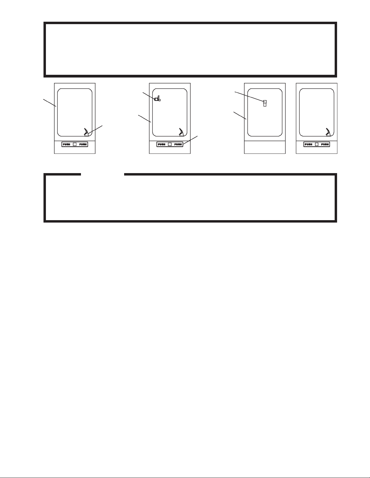
SEE FIG. 3
SEE FIG. 7
21
22
20
SEE FIG. 4
SEE FIG. 9
EDFB12C EDFBC212CEDFB12FC
Installer
T o assure you install this model easily and correctly , PLEASE READ THESE SIMPLE
INSTRUCTIONS BEFORE ST ARTING TH INST ALLATION. CHECK YOUR INST ALLATION FOR COMPLIANCE WITH PLUMBING, ELECTRICAL AND OTHER APPLICABLE
CODES. After installation, leave these instructions inside the fountain for future reference.
IMPORTANT
ALL SERVICE TO BE PERFORMED BY AN AUTHORIZED SERVICE PERSON
IMPORTANT! INSTALLER PLEASE NOTE.
THE GROUNDING OF ELECTRICAL EQUIPMENT SUCH AS TELEPHONE, COMPUTERS, ETC. T O WATER LINES
IS A COMMON PROCEDURE. THIS GROUNDING MA Y BE IN THE BUILDING OR MA Y OCCUR AW A Y FROM THE
BUILDING . THIS GROUNDING CAN CAUSE ELECTRICAL FEEDBACK INTO A FOUNTAIN, CREA TING AN ELECTROLYSIS WHICH CAUSES A MET ALLIC TASTE OR AN INCREASE IN THE METAL CONTENT OF THE WA TER.
THIS CONDITION IS A VOIDABLE BY USING THE PROPER MATERIALS AS INDICA TED. ANY DRAIN FITTINGS
PROVIDED BY THE INST ALLER SHOULD BE MADE OF PLASTIC TO ELECTRICALL Y ISOLA TE THE FOUNT AIN
FROM THE BUILDING PLUMBING SYSTEM.
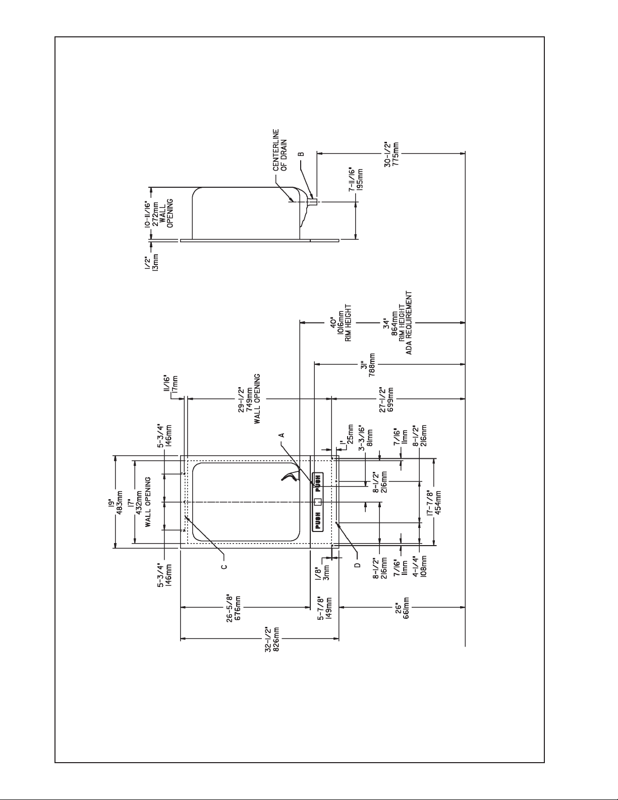
1. Prepare wall opening(s) and attach wall hanger bracket(s) for the fountain (and cuspidor when applicable) using dimensions
shown in Figures 1 and 2.
2. Remove lower panel from drinking fountain (and cuspidor) by removing the two screws at the lower corners. Rotate the bottom
of the panel out to clear the push bar, and pull gently downward to remove.
3. Water supply is 3/8" O.D. unplated copper and waste tailpiece(s) are 1-1/4" O.D. Contractor is to supply waste trap(s) and service
stop valve in accordance with local codes.
4. Connecting lines to be unplated copper and thoroughly flushed to remove all foreign matter before connecting to fountain
assembly.
5. Install fountain (and cuspidor) into rough-in opening(s).
6. Connect the fountain to the supply line with a shut off valve and install a 3/8" (10mm) unplated copper water line between the
valve and strainer. Push the tubes straight into the fittings until they reach a positive stop, approximately 3/4". See Figs. 5 and 6.
DO NOT SOLDER TUBES INSERTED INTO THE STRAINER AS DAMAGE TO THE O-RINGS MAY RESULT.
7. On cuspidor models, connect 1/4 tube coiled in fountain to spreader.
8. Turn water supply on and check thoroughly for leaks.
9. Release air from water line by depressing push bar; a steady stream of water assures all air is removed.
10. Re-check for leaks.
11. Stream height is factory set at 35 PSI. If supply pressure varies greatly from this, turn adjustment screw on regulator (item 23).
Clockwise adjustment will raise the stream height and counter-clockwise adjustment will lower stream height. For best adjust
ment, stream should hit basin approximately 6-1/2" from the bubbler.
1. Orifice Assy: Mineral deposits on orifice can cause water flow to spurt or not regulate. Mineral deposits may be removed from
orifice with a small round file not over 1/8 diameter or a small diameter wire. CAUTION: Do not file or cut orifice materials.
2. Actuation of Quick Connect Water Fittings: Cooler is provided with lead-free connectors which utilize an o-ring water seal.
To remove tubing from the fitting, relieve water pressure, push in on the gray collar while pulling on the tubing (See Fig. 6). To
insert tubing, push tube straight into the fitting until it reaches a positive stop, approximatley 3/4".
INST ALLATION INSTRUCTIONS
TROUBLE SHOOTING AND MAINTENANCE
97165C (Rev. H - 1/05)
EDFB12C*A EDFB12FC*A EDFBC212C*A
FINISHED FLOOR LINE
EDFB12C ROUGH-IN
**
*
*
FIG. 1
C = WALL HANGER - 12" (305mm) x 1" (25mm) FURNISHED LOOSE.
D = MOUNTING HOLES FOR 1/4" DIA. (6mm) SCREWS.
*
97165C (Rev. H - 1/05)
PAGE 2
LEGEND:
A = W A TER INLET LOCA TION. 3/8" O.D. UNPLA TED COPPER
TUBE CONNECT.
B = FOUNT AIN WASTE OUTLET LOCA TION.
1-1/4" O.D. DRAIN (TRAP NOT FURNISHED)
 Loading...