

Page 1
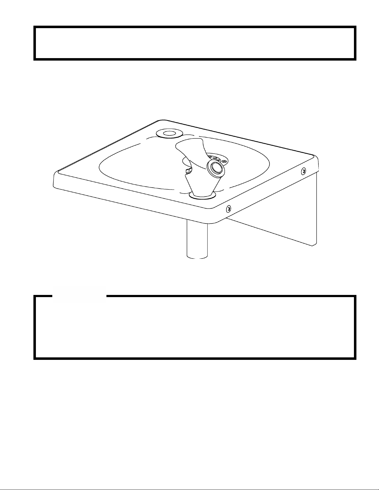
EDF15AC
INSTALLATION/CARE/USE MANUAL
Installer
To assure you install this model easily and correctly,
PLEASE READ THESE SIMPLE INSTRUCTIONS BEFORE STARTING THE
INSTALLATION. CHECK YOUR INSTALLATION FOR COMPLIANCE WITH
PLUMBING, ELECTRICAL AND OTHER APPLICABLE CODES. After installation, leave these
instructions inside the fountain for future reference.
IMPORTANT! INSTALLER PLEASE NOTE.
ALL SERVICE TO BE PERFORMED BY AN AUTHORIZED SERVICE PERSON
THE GROUNDING OF ELECTRICAL EQUIPMENT SUCH AS TELEPHONE, COMPUTERS, ETC. TO
WATER LINES IS A COMMON PROCEDURE. THIS GROUNDING MAY BE IN THE BUILDING OR MAY
OCCUR AWAY FROM THE BUILDING. THIS GROUNDING CAN CAUSE ELECTRICAL FEEDBACK INTO A
FOUNTAIN, CREATING AN ELECTROLYSIS WHICH CAUSES A METALLIC TASTE OR AN INCREASE IN
THE METAL CONTENT OF THE WATER. THIS CONDITION IS AVOIDABLE BY USING THE PROPER
MATERIALS AS INDICATED. ANY DRAIN FITTINGS PROVIDED BY THE INSTALLER SHOULD BE MADE
OF PLASTIC TO ELECTRICALLY ISOLATE THE FOUNTAIN FROM THE BUILDING PLUMBING SYSTEM.
97692C (12/00)PAGE 1
Page 2
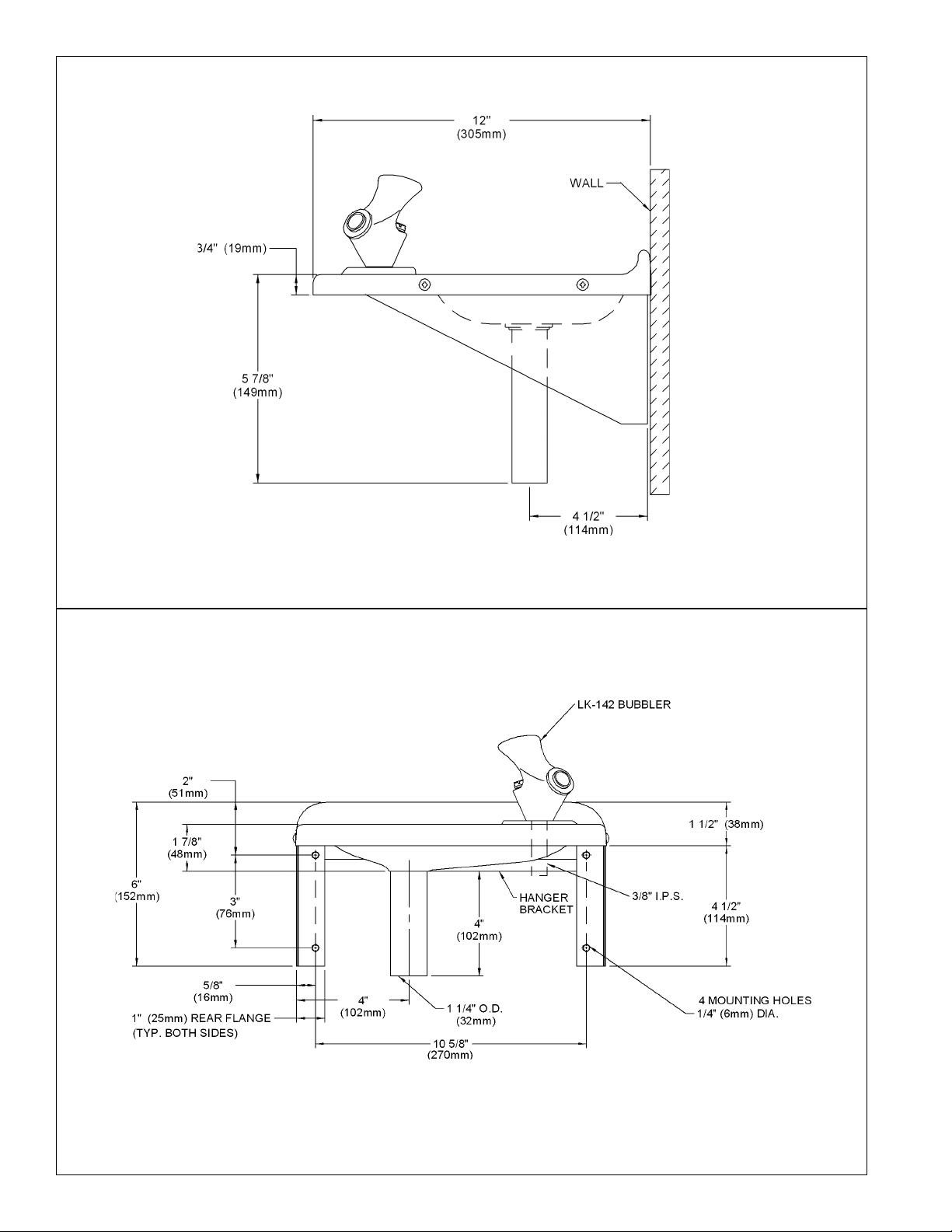
EDF15AC
SIDE VIEW
FRONT VIEW
97692C (12/00) PAGE 2
Page 3

EDF15AC
ASSEMBLY
1. Assemble support brackets to the fountain by aligning holes in bracket with holes in cooler and fastening with
(4) #10 screws provided.
2. Attach bubbler to fountain by inserting bubbler nipple through the hole in the cooler top and securing
with the washer and nut provided.
INSTALLATION
1. This fountain is to be mounted on a smooth, flat, finished wall surface, with adequate support structure.
2. Establish rim height fountain is to be mounted.
3. Refer to rough-in for plumbing.
4. Locate and install trap. (Trap not included).
5. Install shut-off valve on building water supply. (Shut off valve not furnished).
6. Locate and install hanger bracket using 1/4" (10mm) lag screws or bolts. (Not included).
7. Install and center fountain on hanger bracket by slipping the back edge of the cooler top over the
flange on the hanger bracket. Secure fountain using 1/4" (10mm) minimum lag screws or bolts (Not
included).
CAUTION: This fountain is rated for inlet water pressure of 20-105 psi. Should the inlet water supply exceed
105 psi, a pressure reducing regulator should be used.
8. Connect fountain to building supply line by running a 3/8" (10mm) water line between the shut-off
valve and fountain.
9. Turn "ON" water supply and check all connections for leaks.
10. Adjust bubbler stream height. (See instructions below).
TROUBLE SHOOTING AND MAINTENANCE
Orifice Assy: Mineral deposits on orifice can cause water flow to spurt or not regulate. Mineral deposits may be
removed from the orifice with a small round file not over 1/8" diameter or small diameter wire.
CAUTION: DO NOT file or cut orifice material.
Stream Regulator: If orifice is clean, regulate flow as stated below. If replacement is necessary, see parts list for
correct regulator part number.
STREAM HEIGHT ADJUSTMENT: Stream height is factory set
at 45-50 PSI. If supply pressure varies greatly from this, remove
items 11, and 12 (See figure 2) from bubbler assembly and
adjust the screw on the regulator (Item 15). Clockwise adjustment will raise stream height and counterclockwise will lower
the stream height. A stream height of 1-1/2" (38mm) is recommended.
FIG. 1
97692C (12/00)PAGE 3
Page 4

ITEMIZED PARTS LIST
ITEM NO. PART NO.
1
2
3
4
5
6
7
8
9
10
11
12
13
14
15
16
17
18
19
28057C
58000155
58000154
27238C
40294C
70208C
74070020
LK142
10031C
100322740560
40048C
40089C
40322C
45675C
61313C
70012C
72460042
A54800
A54888
DESCRIPTION
Basin Assy.
Bracket - Support LH
Bracket - Support RH
Bracket - Wall Hanger
Tailpipe - 1-1/4 O.D. x 4.00 IN.
Mach. Screw 10-24x3/8
10-24 Hex Nuts (N/S)
Bubbler Assembly
Retaining Nut 1 1/8-24
Gasket
Button
Cover Nut 1 1/8-24
Orifice Assembly
Bubbler Body
Regulator
Lock Nut 3/8-18
Metal Washer
Nipple
Screen
EDF15AC
8
13
14
11
12
15
9
17
18
19
10
16
FIG. 3
See Fig. 2
FIG. 2
1
4
2
5
ELKAY MANUFACTURING COMPANY 2222 CAMDEN COURT OAK BROOK, IL 60523 630.574.8484
PRINTED IN U.S.A.
97692C (12/00) PAGE 4
FOR PARTS, CONTACT YOUR LOCAL DISTRIBUTOR OR CALL 1.800.323.0620
3
6
 Loading...