

Elkay ECU8-3 Installation Manual
ECU8-1, ECU8-2, ECU8-3
Installation Instructions
Refrigeration Packages
INSTALLATION
1. Insure proper ventilation. In fully recessed drinking fountains be sure condenser faces louver panel and is
within 1/2" (13 mm) of louver panel when panel is in place.
2. Water inlet is 3/8" (10 mm) O.D. tube connector. Contractor to supply connections as required.
3. Connecting lines to be made of copper. Thoroughly flush all lines to remove all foreign matter before
connecting to cooler.
4. Connect cooler to building supply with a shut-off valve and install a 3/8" (10 mm) water line between the valve
and cooler. Remove burrs from outside of water line. Insert water line into bulkhead union until it reaches a
positive stop, approximately 3/4" (19 mm).
5. Electrical: Make sure power supply is identical in voltage, cycle, and phase to that specified on cooler serial
plate. Never wire the compressor directly to the power supply.
IMPORTANT! INSTALLER PLEASE NOTE:
The grounding of electrical equipment such as telephone, computers, etc., to water lines is a common procedure.
This grounding may be in the building, or may occur away from the building. This grounding can cause electrical
feedback into a water chiller, creating an electrolysis which causes a metallic taste or an increase in the metal
content of the water. This condition is avoidable by using the proper materials indicated below. Drain fittings which
are provided by the installer should be plastic to electrically isolate the chiller from the building plumbing system.
START-UP
1. Open supply line valve.
2. Purge all air from all water lines by operating bubbler valve of fountain to which cooler is connected. A steady
stream flow assures that all air is removed.
3. Rotate fan blade to assure proper clearance and free action.
4. Connect to proper electrical power.
TROUBLE SHOOTING & MAINTENANCE
Temperature Control: Factory-set for 50°F water (± 5°) under normal conditions. For colder water, adjust screw
on item no. 5.
Ventilation: Cabinet louvers and condenser fins should be periodically cleaned with a brush, air hose, or vacuum
cleaner. Excess dirt or poor ventilation can cause no cold water and compressor cycling on the overload
protector.
Lubrication: Motors are lifetime lubricated.
Actuation of Quick Connect Water Fittings: Cooler is provided with lead-free connectors which utilize an o-ring
seal. To remove tubing from the fittings, relieve water pressure, push in on gray collar while pulling on the
tubing. To insert tubing, push tube straight into fitting until it reaches a positive stop, approximately 3/4.
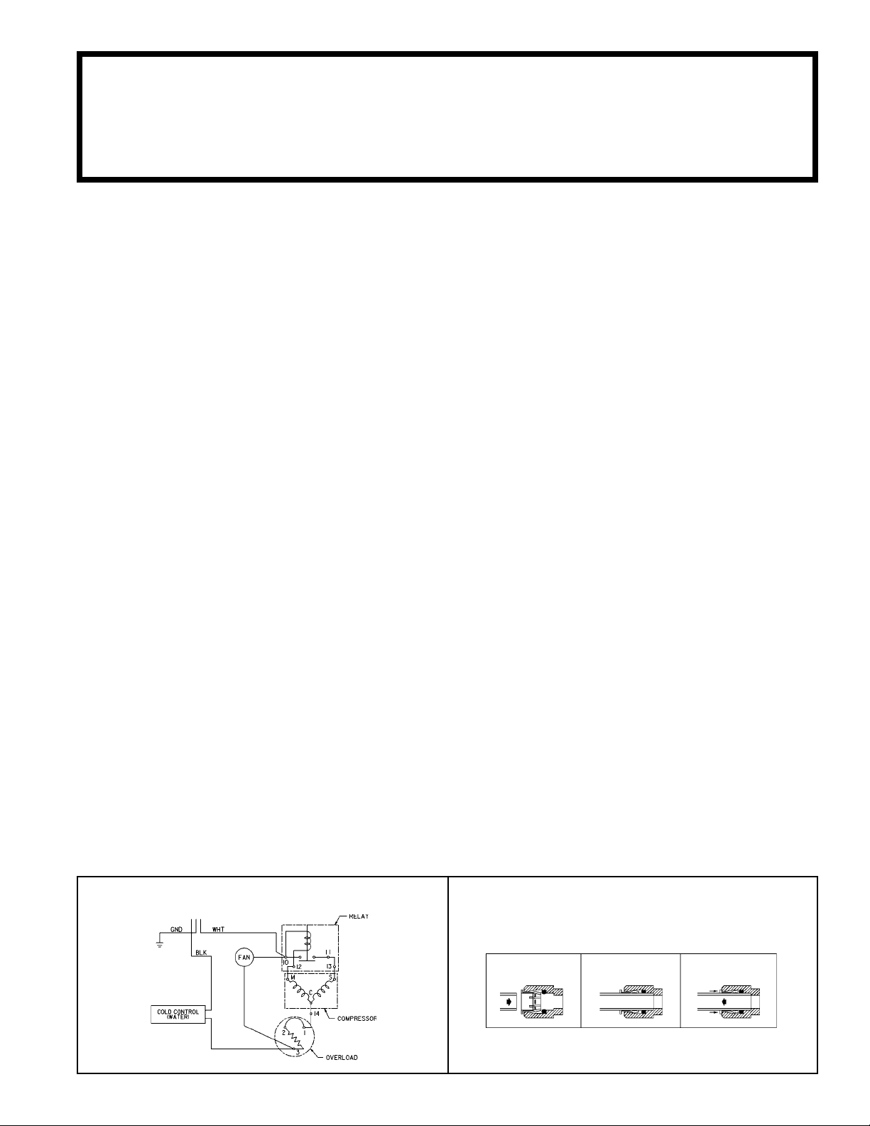
WIRING DIAGRAM
OPERATION OF QUICK CONNECT FITTINGS
SIMPLY PUSH IN
TUBE TO ATTACH
TUBE IS SECURED
IN POSITION
PUSH IN COLLET
TO RELEASE TUBE
PUSHING TUBE IN BEFORE
PULLING IT OUT HELPS TO
RELEASE TUBE
96645C (Rev. E)
ECU8-1, ECU8-2, ECU8-3
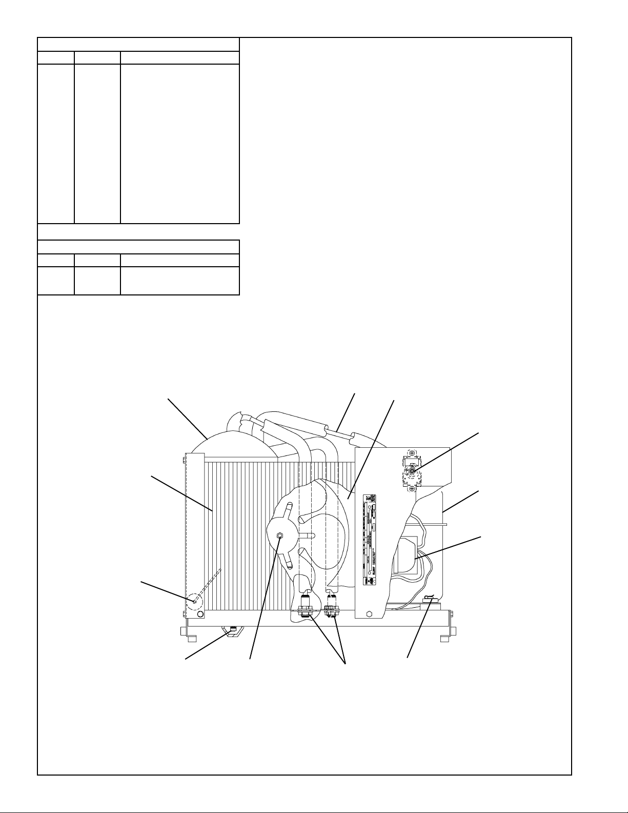
PARTS LIST
ITEM NO.
1
2
3
4
5
6*
7
8
9
10
11
12
13
14
15
16
17
18
NS
PART NO.
66421C
50189C
66263C
70841C
31513C
35767C
31025C
19037000
101516143550
100806740570
20282C
31490C
70018C
30664C
66202C
66305C
70767C
70772C
31504C
EVAPORATOR
SHROUD
HEAT EXCHANGER
UNION - BULKHEAD
COLD CONTROL
COMPRESSOR SERV. PAK
OVERLOAD/RELAY ASSY
CLIP - COMPRESSOR MTG
STUD - COMPRESSOR MTG
GROMMET - COMPRESSOR MTG
BRACKET - FAN MTG
FAN MOTOR
NUT
FAN BLADE
DRIER
CONDENSER
EVAPORATOR RETAINING CLIP
EVAPORATOR DRAIN PLUG
POWER CORD
DESCRIPTION
220/240 50/60HZ PARTS LIST
ITEM NO.
PART NO.
6*
7
15
35763C
31024C
31430C
COMPRESSOR SERV. PAK
OVERLOAD/RELAY ASSY
FAN MOTOR
*INCLUDES RELAY & OVERLOAD. IF UNDER WARRANTY REPLACE
WITH SAME COMPRESSOR USED IN ORIGINAL ASSEMBLY.
NOTE: ALL CORRESPONDENCE PERTAINING TO ANY OF THE ABOVE
WATER COOLERS OR ORDERS FOR REPAIR PARTS MUST INCLUDE
MODEL NO. AND SERIAL NO. OF COOLER, NAME AND PART NO. OF
REPLACEMENT PART.
DESCRIPTION
15
16
1
3
2
5
6
7
11, 12, 13, 1417, 18
4
8, 9, 10
96645C (Rev. E)
FOR PARTS, CONTACT YOUR LOCAL DISTRIBUTOR OR CALL 1.800.323.0620
ELKAY MANUFACTURING COMPANY2222 CAMDEN COURTOAK BROOK, IL 60523630.574.8484
 Loading...