

Page 1
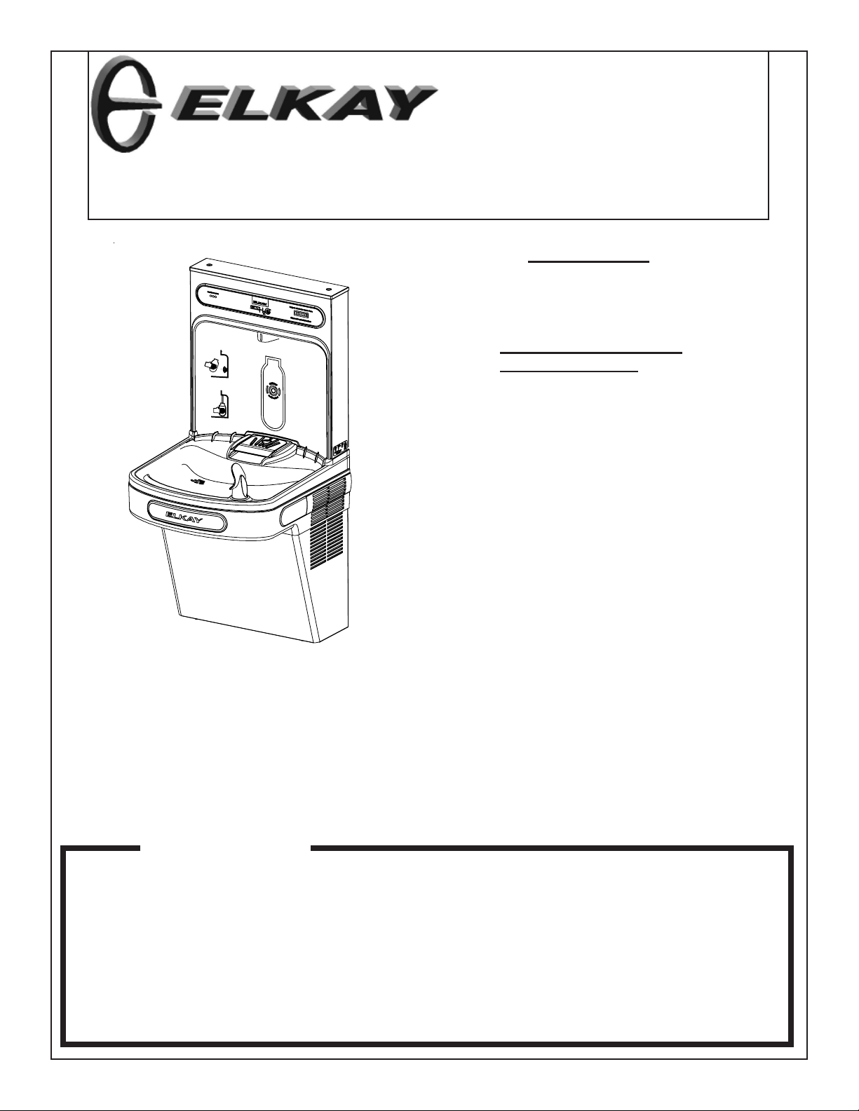
LZWSR*1B
INSTALLATION, CARE & USE MANUAL
TM
LZWSRK -EZH2O RETRO-FIT BOTTLE FILLING UNIT
IMPORTANT
THIS IS AN INDOOR APPLICATION ONL Y .
ALL SERVICE TO BE PERFORMED BY AN
AUTHORIZED SERVICE PERSON.
TOOLS REQUIRED
BUT NOT PROVIDED:
SAFETY GLASSES
GLOVES
1-3/8” HOLE PUNCH (PROVIDED)
1/2” DRILL BIT
ELECTRIC DRILL
3/4” WRENCH OR CRESCENT WRENCH
5/16” NUT DRIVER
UTILITY KNIFE
T APE MEASURE
PENCIL
CENTER PUNCH
1/2” SOCKET & RA TCHET WRENCH
5/32” ALLEN WRENCH
7/64” ALLEN WRENCH
IMPORTANT! INSTALLER PLEASE NOTE.
THE GROUNDING OF ELECTRICAL EQUIPMENT SUCH AS TELEPHONE, COMPUTERS, ETC. TO WA TER LINES
IS A COMMON PROCEDURE. THIS GROUNDING MA Y BE IN THE BUILDING OR MA Y OCCUR A WA Y FROM THE
BUILDING . THIS GROUNDING CAN CAUSE ELECTRICAL FEEDBACK INTO A FOUNT AIN, CREA TING AN ELECTROL YSIS WHICH CAUSES A MET ALLIC T ASTE OR AN INCREASE IN THE METAL CONTENT OF THE WA TER.
THIS CONDITION IS A VOIDABLE BY USING THE PROPER MA TERIALS AS INDICA TED. ANY DRAIN FITTINGS
PROVIDED BY THE INST ALLER SHOULD BE MADE OF PLASTIC T O ELECTRICALLY ISOLA TE THE FOUNT AIN
FROM THE BUILDING PLUMBING SYSTEM. WE SUGGEST THA T THE BOTTLE FILLING ST A TION AND W A TER
COOLER BE PROTECTED BY A GROUND F AUL T CIRCUIT INTERRUPTER (GFCI).
INSTALLER
LZWSR Bottle Fillers are among the easiest to install on the market today. To
insure you install these models easily and correctly, PLEASE READ THESE
SIMPLE INSTRUCTIONS BEFORE STARTING THE INSTALLATION. CHECK
YOUR INSTALLATION FOR COMPLIANCE WITH PLUMBING, ELECTRICAL, AND
OTHER APPLICABLE CODES. After installation, leave these instructions with the
Cooler for future reference.
Page 1 98674C (Rev. D - 9/11)
Page 2
LZWSR*1B
WATER COOLER PREPARATION
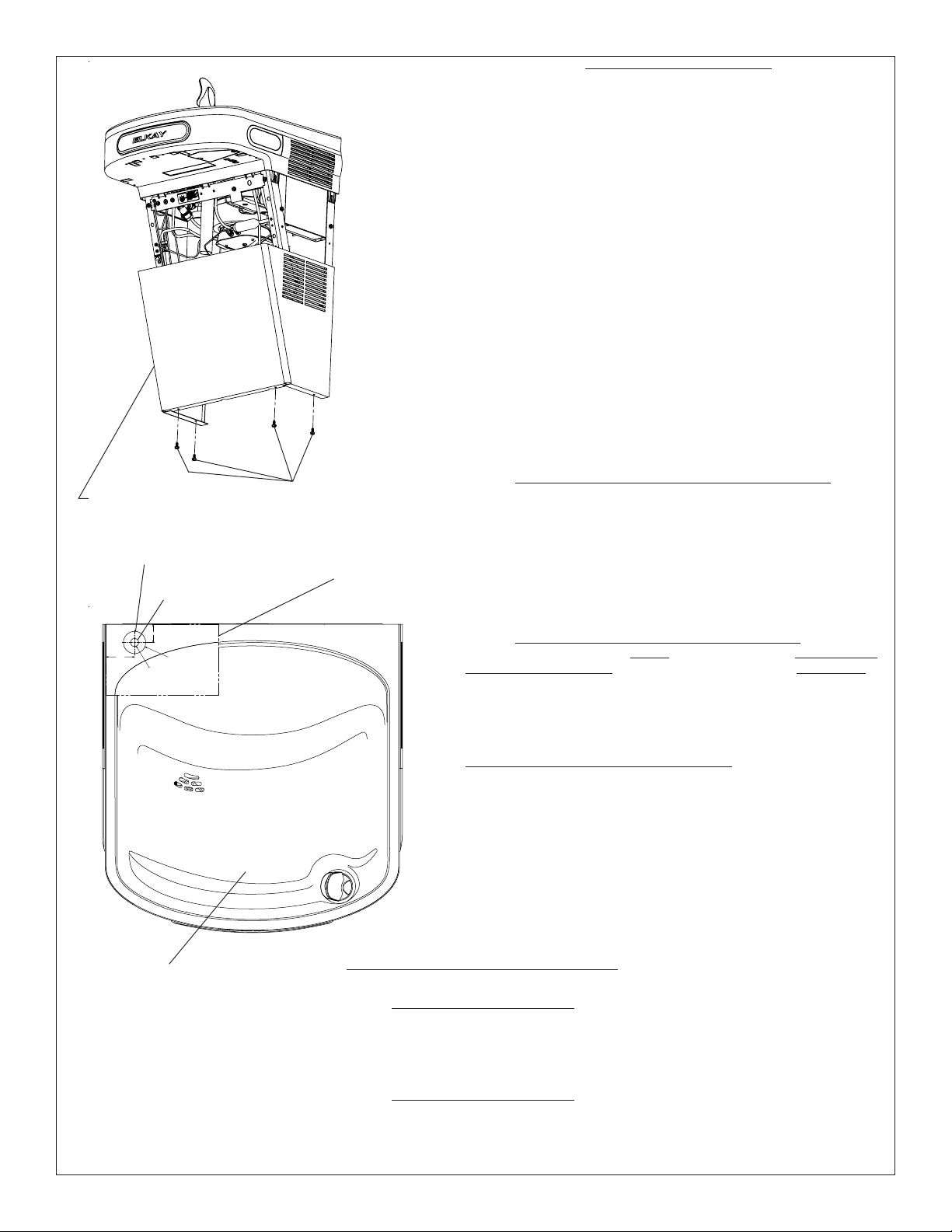
1) Remove lower front panel of watercooler by removing the four (4) screws from
the bottom of cooler. (See FIG. 1) NOTE: For Two Level Models the Bottle Filling
Unit should be mounted to the higher unit. Both lower front panels and basin
assemblies will need to be removed.
1a) For units with model no’s. ending with 1, 1A, 2 or 3 these units will need to
be removed from the wall in order to remove the basin assembly(s).
2) Power OFF circuit that the water cooler is connected to by switching the
circuit breaker to the “OFF” position or by removing the fuse to the circuit.
Remove the water cooler plug from the outlet and shut off water supply.
3) Cut out the Drain Mat template located on the last page of the manual and
place the template on rear left side of the EZ cooler basin.
4) Locate 1-3/8” diameter hole on left side of the template (See FIG. 2). Mark
center of hole on basin with pencil.
5) Remove Basin Assembly by loosening four (4) screws two on each side of
cooler as shown in Fig. 5. Disconnect water line “A” from bubbler at the
evaporator tank (See Fig. 3). NOTE: When disconnecting water lines use a
container to catch any water running out of the lines. Disconnect basin
assembly from drain trap. Lift basin assembly straight up to remove, and
disconnect two wires from push bar switches. (Note: This will allow easier
assembly of water filter to unit and pressurization of the unit.)
5a) For units referenced in step “1a”. Remove Basin Assembly by loosening
four (4) screws two on each side of cooler as shown in Fig. 5. Remove 2 screws
from top back of unit to remove the “L” bracket. Remove 1 screw from left side of
cross brace in front of unit that retains the drain support. Disconnect water line
“A” from regulator at the evaporator tank (See Fig. 3B). NOTE: When disconnecting water lines use a container to catch any water running out of the lines.
Disconnect basin assembly from drain trap. Lift basin assembly straight up to
remove, and disconnect two wires from push bar switches.
will allow easier assembly of water filter to unit and
pressurization of the unit.)
SCREWS
LOWER COVER
Fig. 1
NOTICE: Do not use with water that is microbiologically unsafe or of
unknown quality without adequate disinfection before or after the system.
1) These filter kits must be installed in compliance with all state and local laws
and regulations governing the installation and use of this product. Maximum
inlet water temperature 100°F (38°C).
1-3/8” DIA. HOLE
1 1/8"
1 3/4"
1/2"O
PILOT
HOLE
EZH20 RETRO-FIT BOTT L E
LEFT SIDE
BASIN HOLE TEMPLATE
1/2” DIA. HOLE
WALL
1-3/8"O
PUNCHED
HOLE
FILLER
PAPER
TEMPLATE
2) See filter instructions for filter assembly. Insert 3/8” elbow fitting into the
inlet side of filter head, insert 1/4” polytube or 1/4” x 90° elbow into outlet side
of filter head prior to mounting the filter head assembly into the cooler.
3) Mount filter head as shown in Fig. 6, using the filter mounting bracket and
screws supplied. For Two-Level units the filter must be mounted to the L.H.
non-refrigerated unit at the same location as shown in Fig. 6.
NOTE: This proceedure MUST be performed on ALL SINGLE
EZ WATER COOLERS or the bottle filling unit WILL NOT
perform properly!
1) Remove water inlet (B) and outlet (C) from solenoid valve (See Fig. 3 or 3B).
NOTE: When disconnecting water lines use a container to catch any water
running out of the lines.
2) CAUTION: If supply pressure will ever exceed 100 psi, install a pressure
regulator to limit the inlet pressure to the filter to 100 psi or below.
DO NOT ATTACH HOT WATER LINE TO FILTER. To make connections on the
filter head, loosen locknut. Push the tube end past both o-rings to a positive
stop in the filter head recess - approx. 1", locknut may have to be backed out a
little more. Screw the locknut hand tight to seal (See Fig. 7). Ends of tubing
must be cut square and free of burrs and sharp ends that could cut or nick the
o-rings.
3) Connect the outlet of the filter to the inlet of the evaporator using the 1/4"
O.D. poly tubing and 1/4" union supplied (See Fig. 4 or 4B).
4) Cut a 12” long piece of poly tube (besure to insulate poly tube with supplied
insulation tubing) and insert one end into the outlet side of the evaporator “D”
(See Fig. 4 or 4B), connect Tee to other end of tube.
5) Cut a 12” long piece of poly tube (besure to insulate poly tube with supplied
insulation tubing) and insert into the Tee and the other end into the inlet side of
the solenoid valve “E” (See fig. 4 or 4B).
EZ BASIN
Fig. 2
TWO-LEVEL MODIFICATION OF WATER SYSTEM
NOTE: Two-Level water systems are already plumbed for pressurization.
STANDARD TWO-LEVEL MODELS
Follow instruction 2 thru 4 under “Pressurization of water system” to attach filter to water system. The non-refrigerated side must be removed from the wall
in order to remove the basin assy. and install the filter head assy.
1) Remove the Two-Level Cover Plate from the right hand side of the non-refrigerated unit in order to access the rear Basin Assy. screw.
2) Cut poly tube “H” between the existing tee and the solenoid valve of the L.H. unit.
3) Insert supplied 1/4” Tee in water line “H” where it was just cut (See Fig. 4A).
TWO-LEVEL REVERSED MODELS
Follow instruction 2 thru 4 under “Pressurization of water system” to attach filter to water system. The non refrigerated side must be removed from the wall
in order to remove the basin assy. and install the filter head assy.
1) Remove the Bi-Level Cover Plate from the left hand side of the refrigerated unit in order to access the rear Basin Assy. screw (See Fig 5).
2) Cut poly tube “H” approximately 3” from the left side of the existing tee.
3) Insert supplied 1/4” tee in water line “H” where it was just cut.
EWF3000 WATERSENTRY PLUS FILTER INSTALLATION
PRESSURIZATION OF WATER SYSTEM
(Note: This
Page 298674C (Rev. D - 9/11)
Page 3
LZWSR*1B
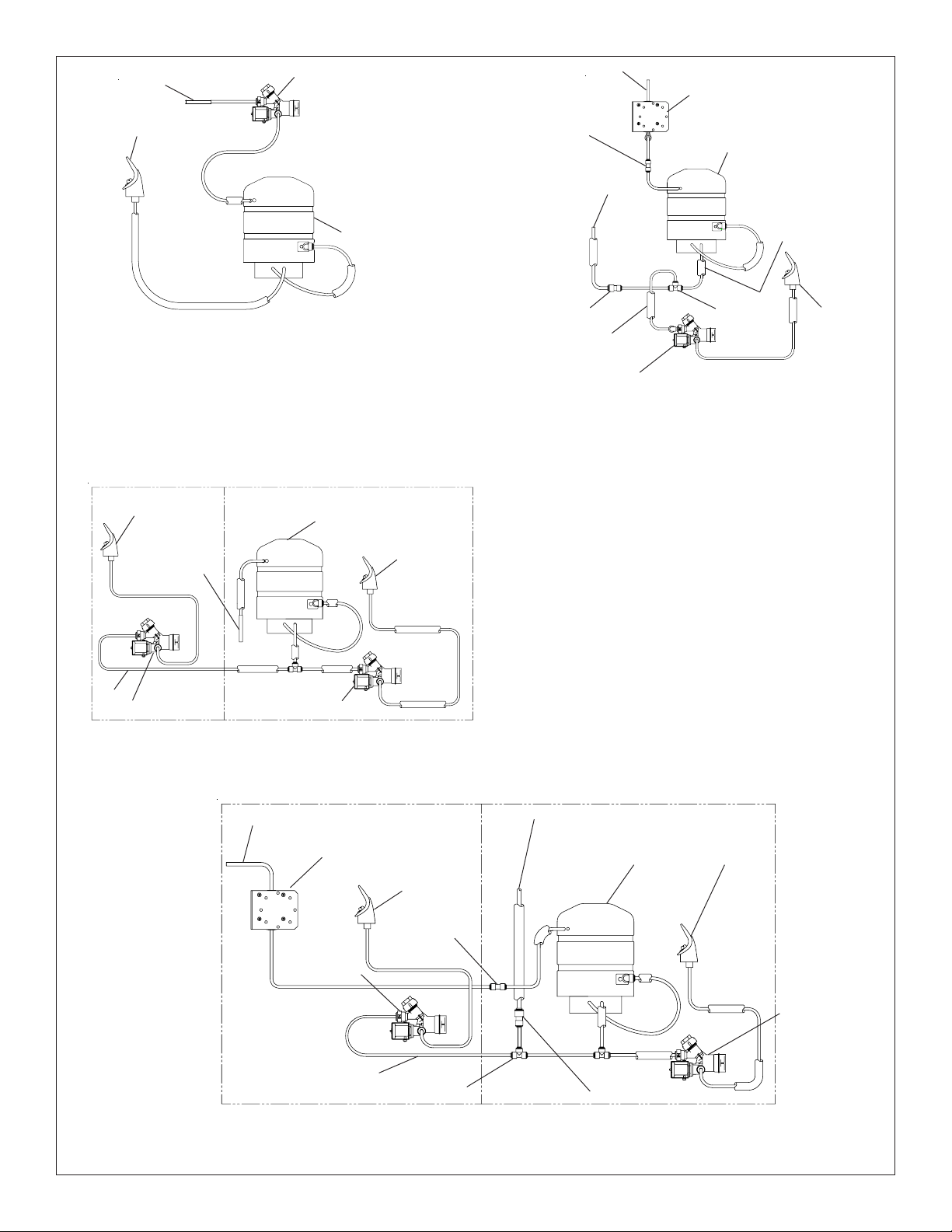
Water Inlet
Bubbler
EZ Non-Pressurized
Plumbing Diagram
L.H. Non-Refrig unit
Bubbler
B
Fig. 3
Solenoid Valve
C
Evaporator
A
R.H. Refrig. unit
Evaporator
3/8” Water Inlet
1/4” Union
3/8” Water Line
from Bottle
Filling Unit
3/8” To 1/4” Union
Tube Insulation
Solenoid Valve
Pressurization Modifications
Filter Assembly
Evaporator
D
G
E
1/4” Tee
F
Tube Insulation
EZ Plumbing Diagram after
Filter Installation &
Fig. 4
Bubbler
H
Solenoid Valve
Water Inlet
Solenoid Valve
L.H. Non-Refrig unit
3/8” Water Inlet
Filter Assembly
Solenoid Valve
Bubbler
Standard EZ Two Level
Pressurized Plumbing Diagram
Fig. 3A
R.H. Refrig. unit
3/8” Water Line from
Bottle Filling Unit
BubblerEvaporator
Bubbler
1/4” Union
H
1/4” Tee
3/8” To 1/4” Union
EZ Two Level Plumbing Diagram after Filter Installation
& Bottle Filler Water Line Addition
Fig. 4A
Page 3 98674C (Rev. D - 9/11)
Solenoid Valve
Page 4
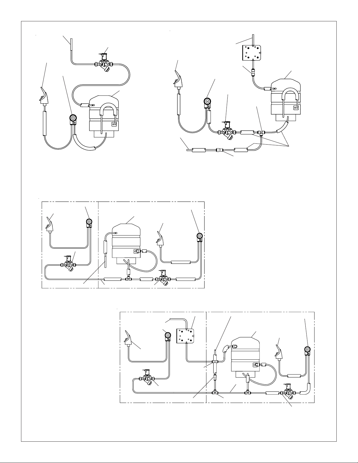
Water Inlet
LZWSR*1B
Plumbing Diagrams for EZ Coolers w/model no’s ending with 1, 1A, 2, & 3
Solenoid Valve
3/8” Water Inlet
Bubbler
Regulator
B
EZ Non-Pressurized
Plumbing Diagram
Fig. 3B
L.H. Non-Refrig unit
Regulator
Bubbler
C
A
Evaporator
3/8” Water Line from
Bottle Filling Unit
R.H. Refrig. unit
Evaporator
Regulator
Bubbler
Bubbler
1/4” Union
Regulator
Solenoid Valve
1/4” Tee
F
E
3/8” To 1/4” Union
EZ Plumbing Diagram after
Filter Installation &
Pressurization Modifications
Fig. 4B
Evaporator
D
Tube Insulation
Solenoid Valve
Water Inlet
H
Standard EZ Two Level
Pressurized Plumbing Diagram
Fig. 3C
Solenoid Valve
R.H. Refrig. unitL.H. Non-Refrig unit
Filter Assembly
3/8” Water Inlet
Regulator
Bubbler
1/4” Union
Solenoid Valve
EZ Two Level Plumbing Diagram after Filter Installation
Bottle Filler Water Line Addition
3/8” Water Line from
Bottle Filling Unit
Evaporator
H
1/4” Tee3/8” To 1/4” Union
Regulator
Bubbler
Solenoid Valve
Fig. 4C
Page 498674C (Rev. D - 9/11)
Page 5

SCREWS
LZWSR*1B
BASIN ASSEMBLY
FILTER ASSEMBL Y
SCREWS
SCREWS
EWF3000 Filter Location
Basin Assembly Removal
Fig. 5
1) Center punch 1/2” hole location on basin prior to drilling the hole in top of cooler basin using an adequete drill and 1/2” drill bit capable of drilling
through stainless steel (See FIG. 2).
2) Locate 1-3/8” knockout punch tool (provided). Unscrew the top half from the bottom half of the tool.
3) With one hand holding the bottom half, and the other hand holding the top half of the punch, insert the top half bolt through the 1/2” hole in basin,
then reach inside the basin assembly underneath the cooler basin with the bottom half and thread it on to the top half bolt. Tighten bottom half on punch
until finger tight.
4) Using 3/4” wrench or crecent wrench tighten the bolt on top half of punch until basin gives way creating the larger hole. Note tool will turn hard.
5) Once hole is made tool may be discarded.
6) Locate plastic bushing (provided) and place in basin hole by pushing into hole until it snaps into place. This bushing protects the water line, wire(s),
and power cord from sharp edge of basin. This part must be used.
7) For Single Model installations: Attach the purple wire (supplied), on to the open terminal of the solenoid valve.
7a) For Two-Level Model installations: Attach the purple wire (supplied), on to the open terminal of the solenoid valve to the unit that the basin hole
was punched in for the Bottle Filling Station. Attach the yellow wire (supplied), on to the open terminal of the solenoid valve of the other unit.
8) Reassemble Basin Assembly back on to unit. Connect the bubbler water line to the outlet side of the solenoid valve “F” (See Fig.4), be sure to
reconnect the black wire from the pushbar assembly back to the purple or yellow piggyback terminal on the solenoid valve. and the other black wire
back to the cold control or power cord (non-refrigerated unit), fish the purple and/or yellow wire(s) up through basin hole and reattach drain to the trap.
Retighten the 4 screws two per side see Fig. 5.
FOR UNITS WITH MODEL NO’S. ENDING IN 1, 1A, 2, & 3
8a) Remove the white wire from the cold control and connect it to the power cord white wire. Reassemble Basin Assembly back on to unit. Connect the
regulator water line to the outlet side of the solenoid valve “F” (See Fig.4B), be sure to reconnect one black wire from the pushbar assembly back to the
purple or yellow piggyback terminal on the solenoid valve. Connect the other black wire from the pushbar assembly to the piggyback on the cold control.
Fish the purple and/or yellow wire(s) up through basin hole and reattach drain to the trap and reinstall drain support screw to front cross brace.
Reinstall “L” bracket to top back of unit with the 2 screws it was mounted with. Retighten the 4 screws two per side see Fig. 5.
After completing instructions 1 thru 8 or 8a from above on the non-refrigerated side. Install filter head assembly per previous installation instructions
and reinstall basin assembly to the non-refrigerated side, re-attach wiring, bubbler tube (or regulator tube) to solenoid valve and reinstall the two level
cover plate to the left side of the unit. Reinstall non-refrigerated unit to wall and reinstall drain.
After completing instructions 1 thru 8 or 8a from above on the refrigerated side. Install filter head assembly per previous installation instructions and
reinstall basin assembly to the non-refrigerated side, re-attach wiring, bubbler tube (or regulator tube) to solenoid valve and reinstall the two level cover
plate to the left side of the unit. Reinstall non-refrigerated unit to wall and reinstall drain.
BASIN ASSEMBLY PREPARATION
ALL STANDARD TWO-LEVEL MODELS
ALL TWO-LEVEL REVERSED MODELS
Fig. 6
Note: Screw the locknut hand tight to seal
Fig. 7
Fig. 8
Page 5 98674C (Rev. D - 9/11)
Page 6

FIVE PIN
CONNECTOR
LZWSR*1B
FOUR PIN
CONNECTOR
VIOLET TO UNIT
SOLENOID
YELLOW TO
BILEVEL SOLENOID
I.R.
BOARD
LED
BOARD
MAIN BOARD
YELLOW
VIOLET
CONNECTOR
CONNECTOR
CONNECTOR FROM
POWER CORD
LINE VOLT AGE
SMOOTH BLACK
POWERCORD
WIRING DIAGRAM - BOTTLE FILLER 1 15V
GND
PIGGYBACK
TERMINAL ON
POWERCORD
WHITE
RED
SOLENOID
GROUND
GREEN
NEUTRAL WHITE
RIBBED
NOTE: UNITS PRODUCED 2008 AND BEFORE
WILL NEED ADAPTERS T O SWITCH LINE AND
NEUTRAL WIRES.
SOLENOID
VALVE
PURPLE
JUMPER
OR YELLOW
JUMPER
GND
GREEN
SMOOTH
(LINE)
RIBBED
(NEUTRAL)
WIRING DIAGRAM - NON REFRIGERA TED SIDE
OVERLOAD
S
6
3
RELAY
3
1
2
C
M
5
2
1
FAN
WHT
BLK
COLD
CONTROL
PURPLE OR
YELLOW JUMPER
SOLENOID
VALVE
SMOOTH
GREEN
GND
WIRING DIAGRAM - REFRIGERA TED SIDE
RIBBED
GND
Page 698674C (Rev. D - 9/11)
Page 7

LZWSR*1B
7/16” BOLT HOLES FOR
FASTENING UNIT TO WALL
UNIT CENTER LINE
Fig. 9
TOP COVER
MOUNTING
SCREWS
Fig. 10
BOTTLE FILLING UNIT
WALL MOUNTING PLATE
Fig. 11
BOTTLE FILLER INSTALLATION
1) Remove two (2) mounting screws with 5/32” allen wrench holding top cover to Bottle Filler (See FIG. 10). Remove top cover. Note do not discard mounting
screws, they will be needed to reinstall top cover..
2) Remove wall mounting plate from Bottle Filler. Place Wall plate against wall on top of EZ basin. Center the wall plate side to side with the EZ basin. Mark
the six (6) mounting holes with a pencil (See FIG. 9).
3) Remove wall mounting plate from wall. NOTE: Mounting plate MUST be supported securely. Add fixture support carrier if wall will not provide adequate
support.
4) Install wall mounting plate to wall using six (6) 7/16” obround mounting holes (mounting bolts not included) (See FIG. 9). Use appropriate fasteners for
your wall type.
5) Place Drain Mat into position on the bottom of the Bottle Filler Unit.
6) For Single Model installations: Attach the purple wire from cooler to the purple wire on the back of the unit, (Note yellow wire is not used).
6a) For Two-Level model installations: Attach the purple and yellow wires from coolers to the purple and yellow wires on the back of the unit, purple to
purple, yellow to yellow.
7) Remove 3/8” to 1/4” reducing union from end of waterline, (do not throw away it will be needed later). Lay Bottle Filler on water cooler basin and cut
insulation from tube even with bottom of unit, remove this insulation from 3/8” tube, but do not discard. Fish the power cord, and waterline through the
hole on top of water cooler created from the “Water Cooler Preparation” section. NOTE: To prevent scratching the basin place a towel or soft cloth over the
entire basin when working above it.
8) With the power cord and waterline through hole on top of water cooler place Bottle Filler on the three (3) angled tabs protuding from the wall mounting
plate, installed on wall (See Fig. 11). Make sure rubber Drain Mat is installed properly on bottom of Bottle filler (See Cover Illustration).
9) Once Bottle Filler is installed on wall plate tabs, drain mat, water line, wire(s) and power cord are installed properly, push top of Bottle Filler toward wall
and line up top cover two (2) holes.
10) Reinstall Top Cover on Bottle Filler (See FIG. 10) with two mounting screws from step 1 above. Caution do not over tighten screws.
11) Install remaining tube insulation on to water line from bottle filler, connect Bottle Filler waterline inside to the water cooler by connecting the 3/8” water
line with the 3/8” to 1/4” union and short piece of poly tube to the tee. (See Fig. 4, 4A or 4B).
12) Install filter cartridge, remove filter from carton, remove protective cap, attach filter to filter head by firmly inserting into head and rotating filter
clockwise. NOTE: If existing plumbing roughin locations (Drain, Water In, Electric Supply) do not allow the filter to be mounted inside the cooler
cabinet the filter can be installed horizontally below the unit see page 9. A retrofit kit is available to mount the filter beneath the cooler.
13) Turn water supply on and inspect for leaks. Fix all leaks before continuing.
14) Once unit has been inspected for leaks and any leaks found corrected plug Bottle Filler and LZ unit into wall. Be sure to reinstall fuse to the circuit
or switch the circuit breaker back to the “ON” position.
15) Once power is applied to Bottle Filler, the GREEN LED light should illuminate showing good filter status along with the LCD Bottle Counter.
16) Verify proper dispensing by placing cup, hand, or any opaque object infront of sensor area and verify water dispenses. Note: the first intitial
dispenses might have air in line which may cause a sputter. This will be eliminated once all air is purged from the line. NOTE: If your Bottle Filler
Counter continuously advances, see page 7 for wiring changes to the non-refrigerated unit to correct the problem. The included adapter wires may
only be needed on Two-Level Units manufactured before JANUARY 2009.
17) Once unit tests out, install Lower Panel back on EZ water cooler(s). Units are now ready for use.
Page 7 98674C (Rev. D - 9/11)
Page 8

LZWSR*1B
WIRING MODIFICATION FOR NON-REFRIGERATED UNIT IN A TWO-LEVEL COOLER
IF BOTTLE FILLER COUNTER CONTINUOUSLY ADVANCES
1) DISCONNECT POWER TO ALL UNITS BEFORE PROCEEDING!
2) Disconnect ribbed wire (powercord) from the switch wire (from pushbar), add the female to female adapter to wire.
3) Remove the smooth larger black wire (powercord) from the solenoid valve. Connect ribbed wire with female adapter
from step 2 to where the smooth black wire was connected.
4) Add the male to male adapter to the smooth wire removed in step 3.
5) Connect the smooth black wire with male adapter to the swith wire (from pushbar) removed in step 2.
6) Reconnect power to all units. Verify bottle filler counter advances only when water is flowing.
7) Once unit tests out, install lower panels back on EZ water coolers. Units are ready for use.
REVERSE THESE TWO WIRES ON
THE NON-REFRIGERA TED UNIT OF
TWO LEVEL MODELS ONL Y
USING THE PROVIDED
ADAPTERS.
POWERCORD BLACK RIBBED WIRE
MALE TO MALE ADAPTER
POWERCORD BLACK SMOOTH WIRE
FEMALE TO FEMALE ADAPTER
UNIT WITH WIRE ADAPTERS ADDED AND WIRED CORRECTL Y
Page 898674C (Rev. D - 9/11)
Page 9

LZWSR*1B
BF6-BF7-BF8 PROGRAMS
SETTING THE CONTROL BOARD
1) To verify the software program of the control board the
unit will need to be shut down and restarted. The chiller
(if present) does not need to be shut down and restarted.
2) The units lower panel must be open to access the power
cord and wall outlet.
3) Shut down the unit by unplugging the power cord from the
wall outlet.
4) Restart the unit by plugging the power cord back into the
wall outlet.
5) Upon start up the bottle count display will show the
software designation of BF6, BF7, BF8 or BF9.
6) Reference the BF6-BF7-BF8 or BF9 instructions for setting
the control board.
1) To access the program button
the bottle filler. Remove the two (2) screws holding top
cover to bottle filler with a 5/32” allen wrench . Remove
top cover. Do not discard mounting screws, they will be
needed to reinstall the top cover after programming
operations are completetd. The programming button is
loacted at the top right side of the unit on the control board.
VERIFY CONTROL BOARD SOFTW ARE
ACCESSING THE PROGRAMING BUTTON
remove the top cover of
1) Depress the program button for approximately 2 seconds
RESETTING BOTTLE COUNT
until the display changes then release. The display will
change and scroll through two messages:
“RST FLTR” – Reset Filter Status LED
“RST BCNT” – Reset Bottle Count
“RNG SET” – Range Set for IR Sensor
If the program button is not pushed again the display
will scroll through the two messages above for
three cycles and then default back to bottle count
and be back in run mode.
2) When the display changes to "RST BCNT", depress the
button again. The display will change to show current
bottle count value i.e. "BC0033183".
3) Depress the button again and the display will change to
"BTLCT=0" for approximately 2 seconds and then return
to run mode displaying 000000.
4) You can test the bottle counter by running water
approximately 5 seconds to see bottle counter advance 1.
RESET THE FILTER MONIT OR
1) Instructions apply to filtered units only.
2) Depress the program button for approximately 2 seconds
until the display changes then release. The display will
change and scroll through three messages:
“RST FLTR” – Reset Filter Status LED
“RST BCNT” – Reset Bottle Count
“RNG SET” – Range Set for IR Sensor
If the program button is not pushed again the display
will scroll through the three messages above for
three cycles and then default back to bottle count and
be back in run mode.
3) When the display changes to "RST FLTR", depress
the button again. The display will change to show
"FLT=". Depress the button again and the display will
show "FLTR=0".
4) The green LED should now be illuminated indicating
that the visual filter monitor has been reset.
SETTING RANGE OF THE IR SENSOR
1) Depress the program button for approximately 2 seconds
until the display changes then release. The display will
change and scroll through three messages:
“RST FLTR” – Reset Filter Status LED
“RST BCNT” – Reset Bottle Count
“RNG SET” – Range Set for IR Sensor
2) If the program button is not pushed again the display
will scroll through the two messages above for
three cycles and then default back to bottle count
and be back in run mode.
3) When display shows “RNG SET” push program button
once the display will show current value
(can be 1 – 10) i.e. “RNG = 3”.
4) Once display shows current value push the program
button to scroll through value of 1 – 10. Select the
desired range setting.
5) Once range is selected allow approximately 4 seconds
to pass and then the display will go back to bottle counter
and be in run mode.
6) Test bottle filler by placing bottle or hand in front of
sensor to make sure water is dispensed.
Page 9 98674C (Rev. D - 9/11)
Page 10

LZWSR*1B
SETTING THE CONTROL BOARD
VERIFY CONTROL BOARD SOFTW ARE
1) To verify the software program of the control board the
unit will need to be shut down and restarted. The chiller
(if present) does not need to be shut down and restarted.
2) The units lower panel must be open to access the power
cord and wall outlet.
3) Shut down the unit by unplugging the power cord from the
wall outlet.
4) Restart the unit by plugging the power cord back into the
wall outlet.
5) Upon start up the bottle count display will show the
software designation of BF6, BF7, BF8 or BF9.
6) Reference the BF6-BF7-BF8 or BF9 instructions for setting
the control board.
ACCESSING THE PROGRAMING BUTON
1) To access the program button remove the top cover of
the bottle filler. Remove the two (2) screws holding top
cover to bottle filler with a 5/32” allen wrench . Remove
top cover. Do not discard mounting screws, they will be
needed to reinstall the top cover after programming
operations are completetd. The programming button is
loacted at the top right side of the unit on the control board.
RESET THE FILTER MONIT OR
1) Instructions apply to filtered units only.
2) Depress the program button for approximately 2 seconds
until the display changes then release. The display will
change and scroll through two messages:
“RST FL TR” – Reset Filter Monitor
“SETTINGS” – System Settings Sub Menu
If the program button is not pushed again the display
will scroll through the two messages above for
three cycles and then default back to bottle count and
be back in run mode.
3) When the display changes to “RST FLTR”, depress
the button again. The display will change to show
“FLTR =”. Depress the button again and the display
will show “FLTR =0”
4) The Green LED should be illuminated indicating that
the visual filter monitor has been reset.
SETTING RANGE OF THE IR SENSOR
1) Depress the program button for approximately 2 seconds
until the display changes then release. The display will
change and scroll through two messages:
“RST FLTR” – Reset Filter S t atus LED
“SETTINGS” – System Settings Sub Menu
If the program button is not pushed again the display
will scroll through the two messages above for
three cycles and then default back to bottle count
and be back in run mode.
2) When the display changes to “SETTINGS”, depress
the button again. The display will change to show
“RNG SET“- Range set for IR sensor.
“UNIT TYP“ - T ype of unit (REFRIG or NON-RFRG)
“RST BCNT“ - Reset bottle count
3) When display shows “RNG SET” push program
button once the display will show current value
(can be 1 – 10) i.e. “RNG = 3”.
4) Once display shows current value push the
program button to scroll through value of 1 – 10.
Select the desired range setting.
5) Once range is selected allow approximately
4 seconds to pass and then the display will go
back to bottle counter and be in run mode.
6) Test bottle filler by placing bottle or hand in front
of sensor to make sure water is dispensed.
BF9 PROGRAM
SETTING UNIT TYPE
1) Depress the program button for approximately 2 seconds
until the display changes then release. The display will
change and scroll through two messages:
“RST FLTR” – Reset Filter S t atus LED
“SETTINGS” – System Settings Sub Menu
If the program button is not pushed again the display
will scroll through the two messages above for
three cycles and then default back to bottle count
and be back in run mode.
2) When the display changes to “SETTINGS”, depress
the button again. The display will change to show
“RNG SET“- Range set for IR sensor.
“UNIT TYP“ - T ype of unit (REFRIG or NON-RFRG)
“RST BCNT“ - Reset bottle count
3) When display shows “UNIT TYPE” push program
button once the display will show current value
Can be REFRIG or NON-RFRG
4) Push button once to change value. Once value is
selected the display will show the new value.
(Can be REFRIG or NON-RFRG)
“REFRIG“ - stands for refrigerated product. In this
setting the flow rate is estimated at 1.0 gallon per minute.
“NON-RFRG“ - stands for nonrefrigerated product.
In this setting the flow rate is estimated
at 1.5 gallons per minute.
Both “REFRIG“ and “NON-RFRG“ simulate
1 bottle equal to 20 oz.
5) Allow approximately 4 seconds to pass and the display
will return to bottle counter and be in run mode.
RESETTING BOTTLE COUNT
1) Depress the program button for approximately 2 seconds
until the display changes then release. The display will
change and scroll through two messages:
“RST FLTR” – Reset Filter S t atus LED
“SETTINGS” – System Settings Sub Menu
If the program button is not pushed again the display
will scroll through the two messages above for
three cycles and then default back to bottle count
and be back in run mode.
2) When the display changes to “SETTINGS”, depress
the button again. The display will change to show
“RNG SET“- Range set for IR sensor.
“UNIT TYP“ - T ype of unit (REFRIG or NON-RFRG)
“RST BCNT“ - Reset bottle count
If the button is not pushed again the display will scroll
through the three messages above for the cycles and
return to run mode.
3) When display shows “RST BCNT” push program button
once the display will show current value i.e. “0033183”.
4) Once display shows current value push the program
button once more to reset back to 0. The display will
show BTLCT = 0 for approximately 2 seconds and
then return to run mode showing 00000000 bottles.
5) Testing the bottle counter:
REFRIG units: Place bottle or hand in front of sensor
for 9.4 seconds to see bottle counter count 00000001.
(This is based on filling a 20 oz. bottle)
NON-RFRG units: Place bottle or hand in front of sensor
for 6.25 seconds to see bottle counter count 00000001.
(This is based on filling a 20 oz bottle)
Page 1098674C (Rev. D - 9/11)
Page 11

LZWSR*1B
1-3/8” Dia. Hole
1.75
EXISTING
HOLE
3/16” Dia.
2 Holes
A
2.25
B
3.75
Bottom View of Cooler
Fig. 12
SCREWS
PLASTIC BUSHING
SCREWS
FIL TER MOUNTING BRACKET
3/8” WA TER INLET
ALTERNATE FILTER MOUNTING LOCATION
FIL TER ASSEMBLY
Alternate Filter Mounting Location
Fig. 13
1) Using the supplied punch from the Bottle Filler installation, punch a 1-3/8” dia. hole “A” at the existing hole shown in
Fig. 12.
2) Drill two 3/16” dia. hole at location “B” shown in Fig 12.
3) Remove Filter bracket from filter assembly and reinstall as shown in Fig. 13. Be sure the 3/8” water inlet is facing out.
4) Install plastic bushing (supplied) as shown into 1-3/8” hole, bushing must be used so waterlines will not be cut by
sharp edges of base plate.
5) Install filter assembly to bottom of cooler as shown in Fig. 13 with 2-#8 sheet metal screws.
6) Run the inlet and outlet water lines to filter.
7) P/N 98551C - LZ Filter Mounting Cover (Light Gray Granite) or P/N 98568C - LZ Filter Mounting Cover (Stainless Steel)
may be order to enclose the filter beneath the cooler (Not Shown).
Page 11 98674C (Rev. D - 9/11)
Page 12

LZWSR*1B
WATERSENTRY® PLUS FILTER PARTS LIST
ITEM NO. PART NO.
1
2
3
4
5
6
7
51294C
70792C
70823C
70822C
51300C
70818C
22490C
(See Fig. 14)
Filter Head Assy.
Screw #8-18 x .75 PH
Fitting - Superseal 3/8” (10 mm)
Fitting - Superseal 1/4” (6 mm)
Filter Assy
Elbow - 3/8” (10mm)
Bracket
2
DESCRIPTION
7
LISTA DE PIEZAS DEL FILTRO
(Vea Fig. 14)
DESCRIPCIÓN DESCRIPTION
Ensamblado de la Cabeza del Filtro
Tornillo #8-18 x .75 PH
Accesorio - Supersello 3/8" (10mm)
Accesorio - Supersello 1/4" (6 mm)
Ensamblado del Filtro
Codo - 3/8" (10 mm)
Fijador
Drain Cover
LISTE DES PIÈCES DU FILTRE
(Voir Fig. 14)
Ens. de tête de filtre
Vis #8-18 x .75 hp
Raccord - Superseal 3/8" (10mm)
Raccord - Superseal 1/4" (6mm)
Ens. filtre
Coude - 3/8" (10mm)
Support
6
4
3
Drain Mat
1
5
WATER FILTER EXPLODED VIEW DRAIN MAT EXPLODED VIEW
Fig. 14
1) Place Drain Cover on mat and install the four screws as shown in Fig.15.
2) It is recommended that the cover be removed and the drain cover be
cleaned weekly. To dis-assemble or re-assemble the drain cover the mat
can be picked up from the front to access the screws beneath.
Fig. 15
DRAIN MAT ASSEMBLY AND CARE
REPLACEMENT PART KITS
PART NO.
98543C
98544C
98545C
98546C
98547C
98675C
98549C
98551C
98568C
98552C
Kit - Electrical Package115V
Kit - IR Sensor 115V
Kit - Solenoid Valve Replacement 115
Kit - Aerator Replacement
Kit - Top Cover Replacement
Kit - Drain Mat & Cover Replacement
Kit - Hardware & Waterway Parts
Kit - LZ Filter Mounting Cover (L)
Kit - LZ Filter Mounting Cover (S)
Kit - Retro Filter Mounting
DESCRIPTION
Screws
PRINTED IN U.S.A.
IMPRESO EN LOS E.E.U.U.
IMPRIMÉ AUX É.-U.
REPAIR SERVICE INFORMATION TOLL FREE NUMBER 1.800.260.6640
INFORMATIONS POUR LE SERVICE PAR NUMERO SANS FRAIS 1.800.260.6640
FOR PARTS, CONTACT YOUR LOCAL DISTRIBUTOR OR CALL 1.800.323.0620
POUR OBTENIR DES PIÈCES, CONTACTEZ VOTRE DISTRIBUTEUR LOCAL OU COMPOSEZ LE 1.800.323.0620
ELKAY MANUFACTURING COMPANY • 2222 CAMDEN COURT • OAK BROOK, IL 60523 • 630.574.8484
PARA PIEZAS, CONTACTE A SU DISTRIBUIDOR LOCAL O LLAME AL 1.800.323.0620
NÚMERO GRATIS DE SERVICIO 1.800.260.6640
Page 1298674C (Rev. D - 9/11)
Page 13

WALL
LZWSR*1B
BASIN TEMPLATE
CUT ALONG LINE
O1 3/8
HOLE
PUNCHED
BASIN HOLE TEMPLATE
1 1/8"
O1/2"
HOLE
PILOT
EZH20 RETRO-FIT BOTTLE FILLER
1 3/4"
LEFT SIDE
CUT ALONG LINE
Page 13 98674C (Rev. D - 9/11)
 Loading...