

Elkay Avado LKAV1031CR, Avado LKLFAV1031CR, Avado LKAV1031NK, Avado LKLFAV1031NK Installation & Owner's Manual
SAVE FOR CONSUMER
INSTALLATION / OWNER’S MANUAL
Avado - Pull-Down Kitchen Faucet
LKAV1031CR
LKAV1031NK
LKLFAV1031CR
LKLFAV1031NK
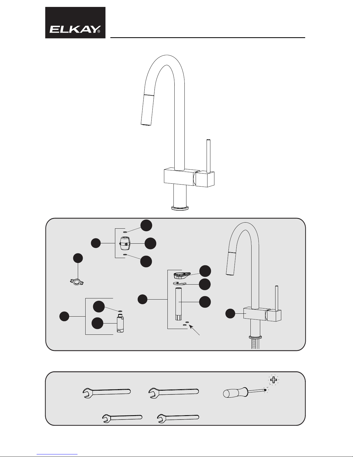
Includes:
Tools:
A
B
D
D
1
D
1
D
2
B
1
B
2
B
3
C
1
C
2
E
1/2”
[13 mm]
13/16”
[20 mm]
5/8”
[16 mm]
13/16”
[21 mm]
C
NOTE: only 1 D1 washer is
used with this faucet model
NOTE: these washers are not
used on this faucet model

WARNING: please carefully read and properly follow the instructions for installation found in this manual.
STEPS:
5
Connect the exible hose s to the su pply connections
with ru bber gaskets.
Secure with wrench .
Turn on the wate r and check fo r leaks.
321
Before dissassemb ling the fauc et be sure that the water supply i s turned of f.
Remove the nish cap (A), pay ing attenti on not to damage it. Remove the setscrew (B) with a 1/8” [2,5mm] hex w rench. Remove t he handle (C). Lif t the nishi ng ring nut (D)
using the reference notch. Unscrew the car tridge nut (E) th en pull out the car tridge (F). Put the new cartridge into the body of the fauc et, checki ng that the two cente ring pins
enter into the respect ive seats (X ) and that the gaskets on the car tridge a re well posit ioned.
Reassmble the handle following the instructions in rever se order.
5/8”
[16 mm]
Hot
Cold
Red
Blue
CARTRIDGE REPLACEMENT
B
A
C
X
1/8”
[2,5 mm]
F
E
1-1/8”
[28 mm]
D
321
Before ins erting the sin gle lever group in the hole of
the sink, ma ke sure that the base gas ket is properly
positi oned in its seat a nd that the exib le hoses are
well tig htened to the bo dy of the tap.
Place the single lever grou p in the h ole of the sink,
orienting the spout toward the sink tank.
For counter top thickne sses less than 1/16” thick
use the ange (B1), for all other installations use
the meta l washer (B2).
Secure mo unting hardware in place by tightening
mounting nut (B3).
Instal l the check valve (C1) to the outlet hose with a
rubber washer (C2).
Secure with wrench .
Attac h the pull- down hose to the bottom of th e
check va lve with a rubb er washer (D1).
Secure with wrench .
13/16”
[20 mm]
1/2”
[13 mm]
4
Attac h the counterweight (D2) to the exible h ose
approximately 15-3/4” [400mm] fr om t he c onnectio n
to the out let pipe.
B
3
B
2
B
1
A
C
2
D
1
C
1
13/16”
[21 mm]
D
2
 Loading...