

Page 1
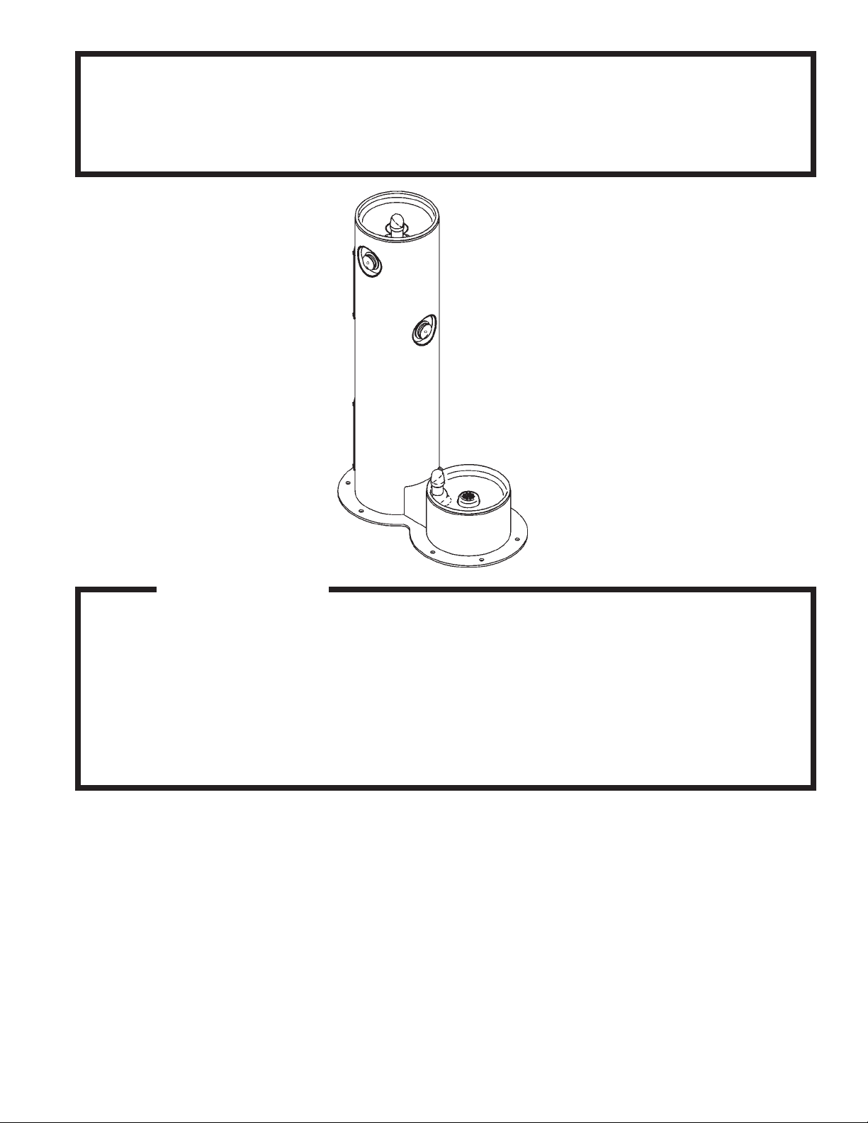
4400DB FOUNT AIN
Owners Manual
Model 4400DB
Tubular Fountain W/Watering
INSTALLER
4400DB Fountains are among the easiest to install Fountains on the
market today. To assure you install these models easily and correctly,
PLEASE READ THESE SIMPLE INSTRUCTIONS BEFORE STARTING THE
INSTALLATION. CHECK YOUR INSTALLATION FOR COMPLIANCE WITH
PLUMBING, ELECTRICAL, AND OTHER APPLICABLE CODES. After installation, leave these instructions with the Fountain for future reference.
IMPORTANT
ALL SERVICE TO BE PERFORMED BY AN AUTHORIZED SERVICE PERSON
IMPORTANT! INSTALLER PLEASE NOTE.
THE GROUNDING OF ELECTRICAL EQUIPMENT SUCH AS TELEPHONE, COMPUTERS, ETC. TO WA TER LINES
IS A COMMON PROCEDURE. THIS GROUNDING MA Y BE IN THE BUILDING OR MA Y OCCUR A WA Y FROM THE
BUILDING . THIS GROUNDING CAN CAUSE ELECTRICAL FEEDBACK INTO A FOUNT AIN, CREA TING AN ELECTROL YSIS WHICH CAUSES A MET ALLIC T ASTE OR AN INCREASE IN THE METAL CONTENT OF THE WA TER.
THIS CONDITION IS A VOIDABLE BY USING THE PROPER MA TERIALS AS INDICA TED. ANY DRAIN FITTINGS
PROVIDED BY THE INST ALLER SHOULD BE MADE OF PLASTIC T O ELECTRICALLY ISOLA TE THE FOUNT AIN
FROM THE BUILDING PLUMBING SYSTEM.
PAGE 1 97801C (Rev. H - 7/06)
Page 2
4400DB FOUNT AIN
PAGE 297801C (Rev. H - 7/06)
Page 3
4400DB FOUNT AIN
1. This fountain is to be mounted on a smooth, flat, finished surface with adequate support structure. NOTE: Mounting structure must be
capable of supporting 300 lb. load on fountain.
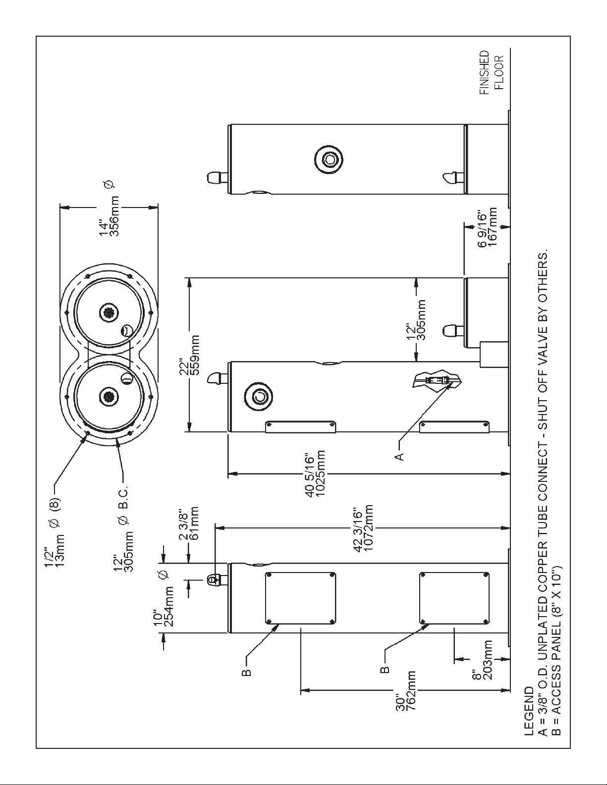
2. Refer to rough-in for plumbing.
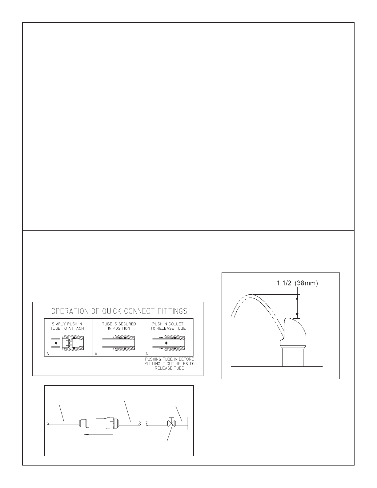
3. Install shut-off valve on water supply , (V alve not furnished)(See Fig. 1).
4. Locate and install fountain using 3/8" minimum screws or bolts, (Screws or bolts not furnished).
5. Connect water supply and fountain drain. Connect drain waste "T ee" to fountain drain tubes. Connect outlet of "T ee" to drainage
system. Water connection and drain must comply with local codes.
6. Turn on water supply and check all connections for leaks.
CAUTION: This fountain is rated for inlet water pressure of 20-105 PSI. A pressure reducing regulator should be used if the inlet water
supply exceeds 105 PSI. Any damage caused by reason of connecting this product to supply line pressures lower than 20
psig or higher than 105 psig is not covered by warranty .
7. Water supply 3/8" O.D. unplated copper tube. Waste 1-1/4" IPS. Contractor to supply waste trap and service stop valve in
accordance with local code.
8. Connecting lines to be made of unplated copper and should be thoroughly flushed to remove all foreign matter before being connected
to fountain. This fountain is manufactured in such a manner that it does not in any way cause taste, odor , color , or sediment problems.
9. Connect fountain to supply line with a shut-off valve and install a 3/8" unplated copper water line between the valve and the cooler .
Remove any burrs from outside of water line. Push the tubes straight into the fittings until they reach a positive stop, approximately
3/4" (See Fig. 2). DO NOT SOLDER TUBES INSERTED INTO THE STRAINER AS DAMAGE TO THE O-RINGS MAY RESUL T .
TROUBLE SHOOTING AND MAINTENANCE
Actuation of Quick Connect Water Fittings:
Fountain is provided with lead-free connectors which utilize an
o-ring water seal. T o remove tubing from the fitting, relieve water
pressure, push in on the gray collar while pulling on the
tubing.(see Fig.2) To insert tubing, push tube straight into fitting
until it reaches a positive stop, approximately 3/4".
FIG. 2
FIG. 3
1/4" O.D. TUBE
WATER INLET
TO COOLER
FIG. 1
3/8" O.D. UNPLATED
COPPER TUBE CONNECT
COLD WATER SUPPL Y
NOTE: WA TER FLOW
DIRECTION
BUILDING WATER INLET
SERVICE STOP
(NOT FURNISHED)
STREAM HEIGHT ADJUSTMENT :
Stream height is factory set at 35 PSI. If supply
pressure varies greatly from this, insert a small straight
bladed screwdriver through the access hole in the
center of the push button and turn the adjustment
screw. Clockwise adjustment will raise the stream and
counterclockwise adjustment will lower the stream. For
best adjustment, the stream should be approximately
1 1/2" above the top of the bubbler . (See Fig. 3)
PAGE 3 97801C (Rev. H - 7/06)
Page 4
4400DB FOUNT AIN
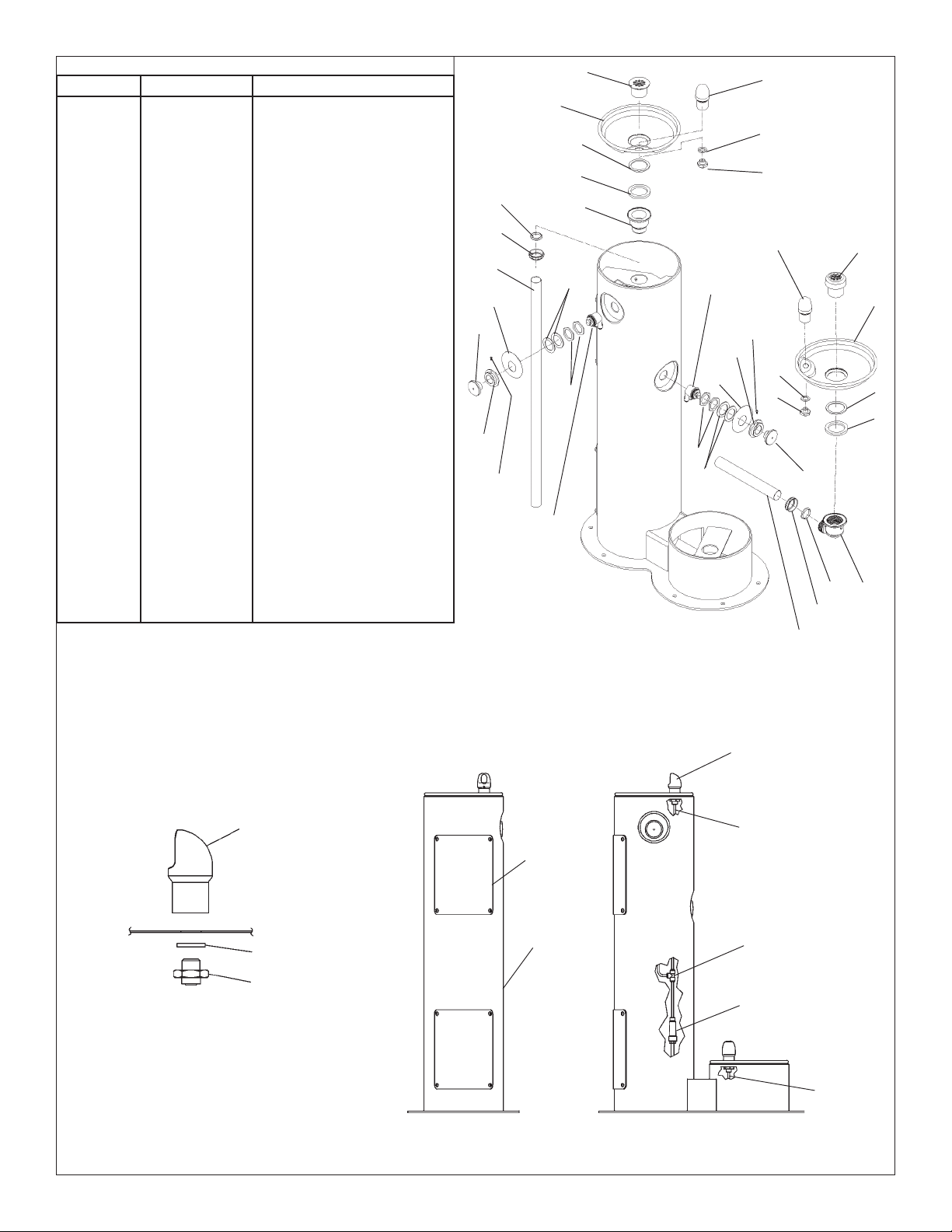
ITEMIZED P ARTS LIST
ITEM NO. PART NO.
1
2
3
4
5
6
7
8
9
10
11
12
13
14
15
16
17
18
19
20
21
22
23
24
25
26
27
28
29
30
NS
NS
NS
For minor scratches a Touch-up Paint Stick is available. For
repairing large defects, off-the-shelf aerosol paint from your local
hardware store can be used. Listed are two suggested
brandnames.
• Brandname: X-O
XO-11 Hunter Green
• Brandname: Ace Hardware
Rust Stop / Machine & Implement
International Green
100147140560
28308C
101570540560
15005C
15009C
28703C
40045C
45725C
98118C
45464C
45831C
45832C
75588C
75589C
45662C
45663C
50986C
56121C
55913C
56092C
55996C
61313C
45724C
75672C
70682C
28467C
75535C
100322740560
45727C
45726C
45476C
75521C
75596C
Touch-up Paint
Drain Gasket
Washer - Spacer
Drain Gasket
Regulator Retaining Nut
Nipple Assy. - Bubbler
Nameplate Insert
Hex Nut 1-5/16"
Tailpipe - 33" Lg.
Bubbler Assembly
Drain Plug 1-1/2"
Fountain Body
Access Panel
Slip Joint Nut 1-1/4"
Seal Washer
Push Button
Push Button Sleeve
Regulator Holder
Drain Elbow
Drain Adaptor
Poly Tubing (Cut To Length)
In - Line Strainer
Regulator
Tailpipe - 10" Lg.
Cap Screw
Tee - 1/4"
Basin
Pinned Torx Screw 1/4-20 x .75"
Washer
Bubbler (DB)
Drain Plug (DB)
Drain Tube
Bit - Torx T-27
Paint Touch-up (Pen)
DESCRIPTION
15
16
14
13
8
6
24
26
4,17,22
10
19
2
7
9
3
1
4,17,22
28
29
5
30
26
24
16
6
28
5
3
1
7
2
15
14
18
13
23
See Fig. 3
PRINTED IN U.S.A.
FIG. 3
9
20
12, 27
28
11
25
5
21
20
FOR PARTS CONT ACT YOUR LOCAL DISTRIBUTOR OR CALL 1.800.260.6640
PAGE 497801C (Rev. H - 7/06)
 Loading...