

Page 1
Voice Siren & Stainless Enclosure ELK-155 RT
APPLICATION
The ELK-155RT is a self-contained Voice Siren mounted in a tampered "No Rust" stainless steel enclosure. It produces
high quality pre-recorded voice messages along with loud siren sounds. It features two (2) channels, one for Burglary and
one for Fire. The voice message and the siren alternately sound whenever one of the channels is activated. The ELK155RT may be customized by use of removable on-board jumper plugs. For example: our MilliMiserTM option allows the
already low current draw of the ELK-155RT to be reduced even lower. This is ideal for controls with limited alarm output
power. The stainless steel exterior reflects the color of the mounting surface allowing the ELK-155RT to blend easily with
any residential or commercial building.
FEATURES
! Installer Friendly - Compact & Easy To Mount.
! Sealed Reed Tamper Switches Front & Back.
! No Rust - No Mess.
! Two Input Channels, Burglar & Fire.
! Bilingual Voice - English Or Spanish.
! Temporal Coded Bell for Fire signalling.
! Speech and Siren or Speech only.
! MilliMiser
! ComboTrigger
! VolumeStep
TM
- Lower Current Draw.
TM
- Single Alarm Outputs.
TM
- Gradual Volume Rise.
SPECIFICATIONS
! Operating Voltage: 10 to 14 Volts D.C.
! Sound Level: 120 db, 13.8 VDC @ 1 meter.
! Nominal Current Drain: 1.25 Amps.
! MilliMiser
! Enclosure: #304 Stainless Steel With
Stainless Hardware Included.
! Size: 5" H x 5" W x 4" D.
! Tamper: Sealed Reed Switches.
! Multiple US Patents Apply
Features or Specifications subject to change without notice.
TM
Current Drain 600 mA.
! Lifetime Limited Warranty, call or visit our website for details.
INSTALLATION
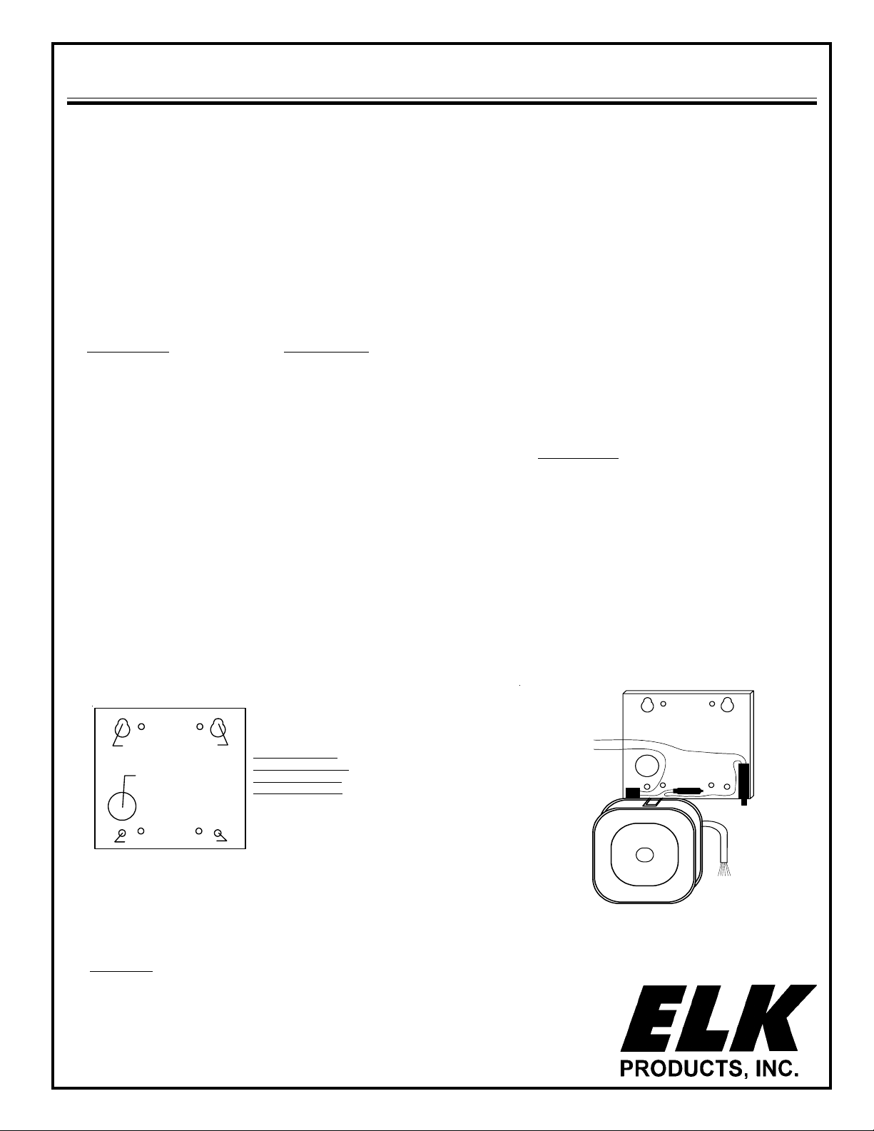
1. Using the backplate as a template, mark & drill 4 mounting holes and the wire or conduit entry hole (see Figure 1). Insert 4 1/4 x 1” wall
anchors, then start the top two #10 x 1” screws.
2. Route the wire or conduit through the hole provided and hang backplate on the top screws. Then install remaining two screws and &
tighten all four.
3. Temporarily hang the Voice Siren/speaker on the backplate by aligning the slotted insert on the top edge of the Siren with the 1/2" recessed
tab on the bottom edge of the backplate. Press Siren onto tab. (See Figure 2), continued on page 2.
Mounting
holes
Wire / conduit
entry hole
Mounting
holes
Mounting
holes
Mounting
holes
Install top edge of
backplate at least 1"
below any soffit or
building overhang.
TAMPER White
TAMPER White
Figure 1
This device has been tested and found to comply with the limits for a Class B digital device,
pursuant to Part 15 of the FCC rules.
Features and Specifications subject to change without notice.
! ELK-SL1 Strobe Light for ELK 155 RT also available
Mounts to bottom of Enclosure,
12 Volts D.C., 140ma.
Available Colors: Clear, Blue, Amber, Red
PO Box 100 • Hildebran, NC 28637 USA • 828-397-4200 Voice • 828-397-4415 Fax
http://www.elkproducts.com • email: [email protected]
05/02
ELK-901G
Figure 2
Page 2
Installation for ELK-155RT (continued)
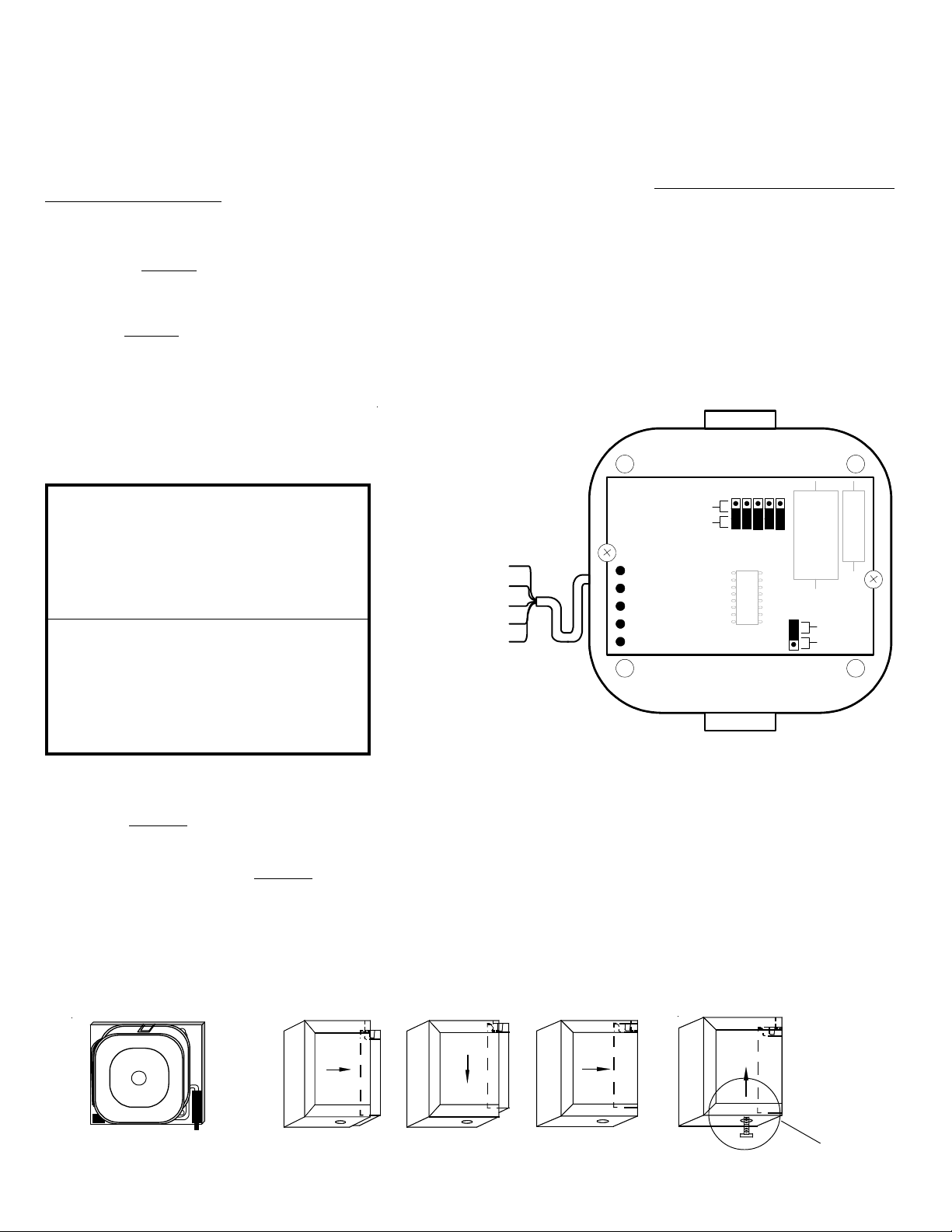
4. Connect all wiring as follows. Recommended wire gauge is 18 AWG.
TAMPER (2 white wires): Connect to a 24 hour closed loop on the control panel. Tamper switch wires are spliced in series.
BLACK (Neg -): Connect to common negative (-) of the control panel.
WHITE (Burglary BA+): Connect to the positive (+) 12 VDC Burglary alarm output terminal. NOTE: This input utilizes our ComboTrigger
recognizes the difference in a steady voltage or a pulsing voltage from the control's alarm "bell" output. If the input voltage is steady the Yelping siren and Burglary voice
message will play. If the input voltage is pulsing (1/2 to 1.5 second intervals) the Bell sound and the Fire message will play,
provided the Red wire is connected to a constant
+12 VDC source as explained below. The ELK-155RT is ideal for controls which have only a single alarm "bell" output.
ORANGE (Fire FA+): Connect to the positive (+) 12 VDC Fire alarm output terminal. Note: It may not be necessary to connect this wire if the control panel can pulse the
alarm "bell" output for a fire alarm condition. Refer to the instructions for the White and Red wires for more information.
RED ( 12 Vdc +):
OPTIONAL Connection of this wire to a positive (+) 12 VDC constant power source allows use of the steady/pulse ComboTrigger
standby current to the microprocessor in the ELK-155RT. NOTE: Most of the operating current will also be drawn from this wire, therefore the power source must be capable of
providing up to 2 Amps of current. It may be necessary to connect this wire directly to the standby battery. If so we recommend using an in-line fuse holder with a 2 Amp fuse
for overcurrent and short circuit protection.
GREEN (BA -): OPTIONAL Some controls, (DSC & others) switch on and off the negative (-) side of the alarm output instead of the positive (+). The ELK-155RT can accomodate
this operation quite well. Simply connect the Green wire to the negative (-) 12VDC Burglary alarm output terminal, the Red wire to the positive (+) alarm terminal, and the black
wire to the common negative (-) terminal of the control. When connected in this manner, this input will also activate the Fire channel message if the alarm output is pulsed on/
off in 1/2 to 1.5 second intervals.
NOTE: The ELK-155RT Siren is factory set for maximum loudness and current draw. To change the unit for lower current draw and loudness, remove jumper J2 for the
TM
MilliMiser
option as described in the "Jumper Options" section.
To change the jumpers, remove the four screws and cover from
the back of the siren, move the desired jumpers, reclose cover.
Jumper Options:
Circuit Board
J1 Closed = Full Volume
Open = Volume StepTM Siren starts off at low volume and
J2 Closed = Full Current.
Open = MilliMiser
J5 Closed = Warble Siren Sound.
Open = Pulsing Buzzer Sound.
English Speech plus Siren = Closed Closed Closed
English Speech Only = Closed Closed Open
Spanish Speech plus Siren = Open Open Closed
Spanish Speech Only = Open Open Open
Spanish and English plus Siren = Closed Open Closed
Spanish and English Only = Closed Open Open
Siren Sounds Only (No Voice) = Open Closed Closed
gradually steps up to full volume in 90 seconds.
TM
draw by approx. 25% with only 8-10% less volume.
Great for controls that have limited alarm current.
Low Current Draw. Reduces current
J3 J4 J7
WHITE (Burglary BA+)
ORANGE (Fire FA+)
BLACK (Neg. -)
RED (12Vdc +)
GREEN (Burglary BA -)
(inside speaker)
Open
Closed
Wiring hookup and view of inside with back removed.
TM
feature which automatically
TM
feature by supplying
J 1
J 2
J 3
J 4
J 5
STEPS
VOL.
SPAN.
LANG.
SOUND
J 7
Closed
Open
VOICE
Voice messages are spoken in English, Spanish/English, or Spanish only, depending upon the switch and jumper settings. (See "Jumper Options"). Each channel has an
VOICE MESSAGES
initial cycle, followed by a repeating cycle.
BA (English): 3 Sec. Tone, Intruder, intruder, leave immediately followed by warble or pulsing buzzer sound. Repeat
FA (English): Fire, fire, leave immediately Followed by a loud distinctive Temporal Coded Bell sound. Repeat
BA (Spanish): 3 Sec. Tone, Intruso, intruso Followed by warble or pulsing buzzer sound. Repeat (Message will alternate in English unless J3 is opened.)
FA (Spanish): Incendio, incendio Followed by a loud distinctive Bell sound. Repeat (Message will alternate in English unless J3 is opened.)
PULSING BA INPUT: (Spanish or English) 3 Sec. Tone, Fire, fire, leave immediately Followed by a Temporal Coded Bell sound. Repeat
5. Move the siren/speaker from its hanging position to its final mount by aligning it's top and bottom slots with the 1/2" tabs on the top edge of the backplate and in the
bottom center above the bolt threads. (See Figure 3) Press firmly.
6. Slide front cover over the siren/speaker. Lift up to engage the tabs in the cover with the two "U" shaped slots on the top edges of the backplate. (Figure 4) Lower
cover until tabs are in slots. Push cover towards wall, then lift up to lock tabs in slots. Thread 1/4-20 hex bolt into hole on bottom of cover and tighten until secure.
7. The front cover tamper switch is pressed closed by the front cover during the final 3 to 4 full turns of the hex bolt. Test the tamper circuit using a continuity meter.
Tuck wires into lower corner
away from top inside corners.
Figure 3
Slide over speaker.
Lower tabs into
slots.
Push towards wall.
Figure 4
Lift up to lock, then
secure with hex bolt.
Tamper switch is closed by
front cover during the final
3 to 4 turns of the hex bolt.
 Loading...