

Page 1
1SHOT
REC/EOM
SW1
RECORD
R15
SIRENVOICE
REPEAT
LED
RECORDDISABLE
+12V NEG
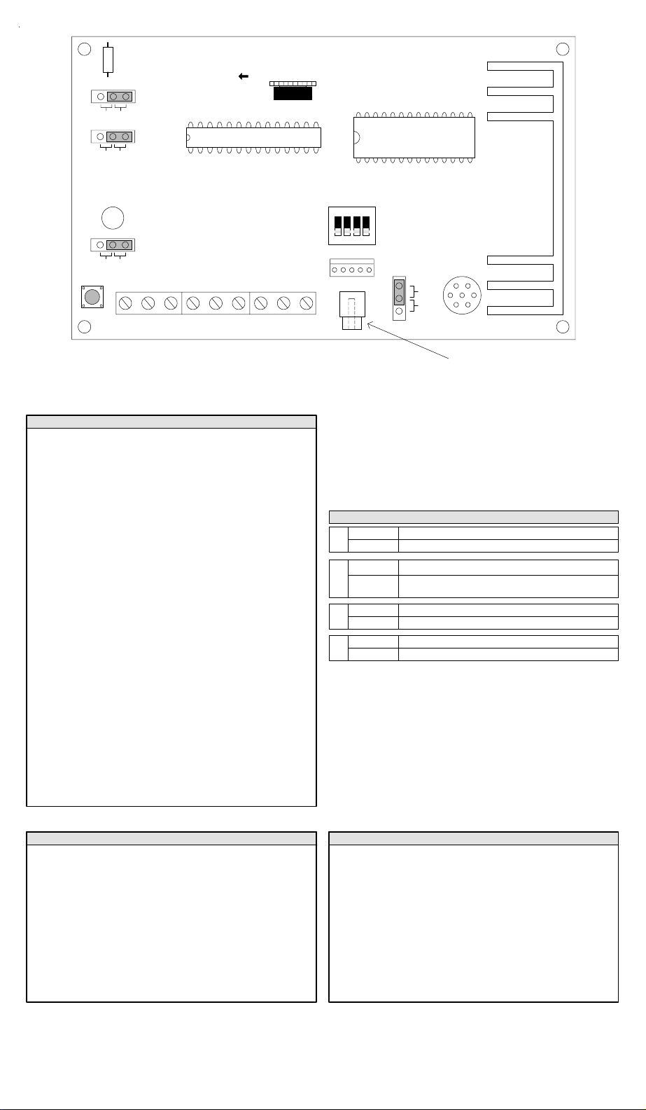
ELK-120 RECORDABLE VOICE AND SIREN MODULE
VOLUME INCREASE
JP4
JP2
JP3
+V1
R21
optional ELK-129
+B4+V2 +S3 SPEAKER-VS
Selects Channel
to be Recorded
Connects to
ELK-120
ACTIVATE
CHANNELS
1234
JP1
PROGRAMMER
LINE OUT
Figure 1
MIC
PRG
MICROPHONE
Line Level Output (RCA Jack)
for connecting to the input of a
paging system or audio amplifier
[+12V] If using a constant 12 Volt DC power source, connect the positive
side here. Nominal operating range of the ELK-120 v.2 is 11 to 14 Volts
DC. This input is only required if: A. The -VS negative trigger terminal is
used. B. Momentary activation of the channels is desired. C. The
activating source equipment is current limited to 30 mA or less.
[NEG] Connect to the negative side of the 12 Volt DC power source. Also
connect the negative from external trigger inputs here if they are from
another power source.
[+V1] Positive trigger input for Voice channel 1
[+V2] Positive trigger input for Voice channel 2
[+S3] Positive trigger input for Yelp Siren or Voice channel 3
[+B4] Positive trigger input for Temporal Coded Horn or Voice channel 4
[-VS] Negative trigger input for controls with a switched negative output
[SPEAKER] Connect to 8 ohm speaker. (Max 4 Ohm load)
[Volume Control (R21)] Adjusts volume of the speaker output.
[Activate Channels] Selects channel to be recorded. Power must be
applied to the +12V and NEG terminals to use this switch.
[Record Switch (SW1)] To record a message, set JP1 to MIC, activate
desired channel, press SW1, then speak your message into the on-board
microphone.
[Programmer (J1)] The optional ELK-129 Computer Sound Card
Interface module connects to this 5 pin connector to allow computer WAV
sound files to be downloaded into the ELK-120.
[Line Out (J2)] This RCA type connector provides line level sound output
for connection to Public Address amplifiers.
NOTE: Channels may be combined to mix the output
Summary of Connection Terminals & Switches
Jumper Settings
MIC Record using the on-board microphone
JP1
PRG Record using the optional ELK-129 sound interface
REPEAT Continuously replays a channel while triggered
JP2
1SHOT
RECORD Enables the on-board record switch SW1
JP3
DISABLE Disables record switch, prevents accidental recordings
SIREN Sets +S3 & +B4 to be Yelp Siren & Horn channels
JP4
VOICE Sets +S3 & +B4 to be Recordable Voice channels 3 & 4
Plays a triggered channel only once.
NOTE: 1Shot is not available for pulsing input mode.
Siren with Voice Mode (JP4 = Siren)(for Alarm Applications)
+V1 = 0 to 8 Minute Recordable Message, see note
+V2 = 0 to 4 Minute Recordable Message
+S3 = Yelp Siren
+B4 = Temporal Coded Horn
+S3 and +B4 together = Industrial Horn
-VS = Alternately plays Yelp Siren and Voice 1 message
Pulsing the +V1 input will play Voice 2 message
Pulsing the +S3 input will play the Temporal Coded Horn
Pulsing the -VS input will alternately play the Horn and Voice 2 message
Note: If Voice 1 (+V1) message recording exceeds 4 minutes, it will
overwrite Voice 2 (+V2) message space, thus +V2 becomes unusable
+V1 = 0 to 8 Minute Recordable Voice 1 Message, see note
+V2 = 0 to 6 Minute Recordable Voice 2 Message
+S3 = 0 to 4 Minute Recordable Voice 3 Message
+B4 = 0 to 2 Minute Recordable Voice 4 Message
-VS = Alternately plays Voice 1 and Voice 3 messages
Pulsing Mode is not available in Voice Mode
Note: If message recordings exceed 2 minutes they will overwrite the
next adjacent message, thus adjacent message becomes unusable
Voice Only Mode (JP4 = Voice)
Page 2

* Try these other fine ELK products *
MM443 Magic Module, 4 Input, 4 Output, Programmable
MM447 Automation Controller w/Voice,Caddx Interface
MV480 Recordable Voice Module, 400 Channels
MKHOME1 Home Control Kit for Caddx NX Controls
MK400 Starter Kit, Includes MM443 & MK485
MK485 Programming Kit, MB485, Cables, Software
MK410 X-10
MK420
MA100 iButton™ ‘Touchkey’ Reader & Interface Pack
MA101 iButton™ ‘Touchkeys’,10 pcs w/keyring holders
MA290 Proximity / Wiegand Data Interface to MM443
MB485 Data Bus Interface, RS232 to RS485
MC100 Clock / Calendar Module for MM443
ML8 Link Interface to Caddx NX Controls
MT100 Temperature Sensor Module for MM443
MM220 Magic Module, 2 Input, 2 Output, Programmable
1RT Speaker & Stainless Steel Enclosure
150RT Siren & Stainless Steel Enclosure
155RT Voice Siren in Stainless Steel Box
44 Speaker, 30 W,8 Ohm Compact Horn
45 Siren, Compact Horn, 118db
55 Voice Siren, Compact Horn
M120 Siren, Single Tone, 107db, Mini Horn
SP15 Speaker, 15 watt, Small Horn
SP30 Speaker, 30 watt, Horn
SP35 Speaker, 20 watt, Interior
SP40 Speaker, 40 watt, Horn
SS15 Siren, Dual Tone, 110db, Horn
SS30 Siren, Dual Tone, 120db, Horn
SS36 Siren, Dual Tone, 105db, Interior
73 ECHO Speaker, 20 Watt, Interior
74 ECHO Dual Tone Siren, Interior
75 ECHO Voice Siren, Interior
870 ECHO Speaker, Self Amplified
100 High Performance Siren Driver
110 Voice Siren Driver, English & Spanish
120 Recordable Voice Module and Siren
124 Recordable Voice Module, 4 Channels
950 Surge Suppressor, Phone & Power Line
951 Surge Suppressor, Phone - Single Line
955 Surge Suppressor, Phone - Dual Line
912 Compact Relay,12 Vdc, SPDT
912B Heavy Duty Compact Relay,12/24 Vdc, SPDT
924 Sensitive Relay, 12/24 Vdc, DPDT
941 Alarm Output Director
960 Delay Timer Relay, 1 sec. to 60 min.
1240 Battery, Lead Acid, 12v, 5Ah
1270 Battery, Lead Acid, 12v, 8Ah
12100 Battery, Lead Acid, 12v, 12Ah
12170 Battery, Lead Acid, 12v, 18Ah
12250 Battery, Lead Acid, 12v, 25Ah
P112 12 Volts DC, 1 Amp Power Supply w/Enclosure
P124 24 Volts DC, 800mA Power Supply w/Enclosure
P1216 12 Volts DC, 1.5 Amp Power Supply
P412 12 Volts DC, 4 Amp Power Supply
P624 Power Supply & Battery Charger
PD9 Power Distribution Module
965 Low Battery Cutoff and Power Switch
TRG1640 Transformer, 16.5VAC @ 40 VA
TRG2440 Transformer, 24VAC @ 40 VA
129 Computer Sound Card Interface
800 Audio Amplifier, 10 Watts
900-2 “B” Connectors,Unfilled,500 pcs
902-2 “B” Connectors,Gel filled,500 pcs
980 Telephone Line Fault Monitor
998 Warning Alarm System Decals
999 Double Sided Tape
SL1 Strobe Light, 4 colors available
WK1 Wall Mount Kit for SL1 Strobes
For more information contact your local Distributor or:
ELK PRODUCTS,INC 828-397-4200 FAX 828-397-4415
http://www.elkproducts.com Email: info@elkproducts.com
05/02
Magic Module Series
®
Transceiver Kit, Programmed MM443
iButton™ Access Kit w/ MM443, MA100, MA101
Rust Free Sirens / Speakers
Speakers & Sirens
ECHO™ Sirens & Speakers
Siren & Voice Drivers
Surge Suppressors
Relay Modules
Power Products
Accessories
Multi-Channel Recordable
V oice Module And Siren
ELK-120 V. 2
APPLICATION:
The ELK-120 v.2 features 4 channels that can be
configured as 2 channels of siren and 2 channels
of voice, or all 4 channels can be used for voice.
Either way the voice channels are fully recordable
and are stored in non-volatile memory. Total time
of recording is 8 minutes. The Siren channels offer
a choice of: Classic Yelp Sound, Temporal Coded
Horn, or Industrial Horn.
Multi-Channel
Recordable Voice
Module And Siren
ELK-120 V. 2
FEATURES:
•Four Channels Configurable as: Two Siren and Two
Recordable Voice OR Four Recordable Voice.
Maximum record time is 8 minutes divided
between the number of voice channels.
•Siren Sounds: Classic Yelp Siren, Temporal Coded
Horn, and Pulsing Industrial Horn .
•Temporal Coded Horn meets ANSI standard for
Audible Emergency Evacuation Signaling.
•Recordings stored in non-volatile memory.
•Voice channels accept momentary triggers.
•"One Shot" or Continuous voice playback settings.
•Built-in condenser microphone for recording.
•Adjustable speaker volume and current draw.
•Powerful 24 watt audio amplifier for Speakers.
•Line Level Output for Paging Systems and Amplifiers
•PC sound card interface connector.
•Lifetime Limited Warranty, call for details.
SPECIFICATIONS:
•Operating Voltage: 11 to 14 Volts D.C.
•Adjustable current draw: 1/4 to 1.8 Amps.
•Low current triggers: 9 to 14 Volts DC @ 30 mA.
•Maximum sound level: 122 dB @ 1 meter.
•Maximum speaker loading: 4 Ohms.
•Pulsing input: 1/2 to 1.5 Sec Pulse, 50% duty cycle.
•Size: 3" x 5" x 1.25" (76 x 127 x 32 mm).
Features and Specificaions subject to change without notice
828-397-4200 Voice
828-397-4415 Fax
http://www.elkproducts.com
email: info@elkproducts.com
PO Box 100 • Hwy. 70W • Hildebran, NC 28637 • USA
Instructions Printed On Inside
Page 3

The 4 channels of the ELK-120 v.2 must be configured by Jumper JP4, located in the top left corner of the board. With JP4 in the
OPERATION
Siren position the unit will be configured as 2 recordable voice channels and 2 fixed siren sounds. With JP4 in the Voice position,
the unit will be configured as 4 recordable voice channels. Voice messages are stored in non-volatile memory and may be rerecorded as needed. Simply configure Jumper JP4 according to your choice of operation and connect according to one of the
installation diagrams and the following instructions.
SIREN with VOICE mode
(Jumper JP4 in the SIREN position)
In this mode the 4 channels are split into 2 siren and 2 voice.
The siren channels are +S3 (Yelp) and +B4 (Temporal
Coded Horn). The voice channels are +V1 and +V2 and
have 4 recordable minutes each or 8 minutes combined.
Positive (+) Voltage Activation Terminals
Each channel may be activated by applying 12 Volts DC
between the NEG terminal and the positive (+) input. Both a
siren and voice channel may be activated at the same time
to achieve mixed siren and voice output.
+V1 = Recordable Voice Channel 1 input.
+V2 = Recordable Voice Channel 2 input.
+S3 = Yelp Siren input.
+B4 = Temporal Coded Horn input.
Pulsing Voltage Activation
Terminals +S3 and +V1 can automatically detect a pulsed
versus a steady activation and play the alternate channel.
For example: if channel +S3 (Yelp) is pulsed then channel
+B4 (Horn) will be played. If channel +V1 (Voice 1) is
pulsed then channel +V2 (Voice 2) will be played.
Negative (-) Activation Terminal
There is a single terminal marked -VS for controls (eg: DSC)
that switch the negative of the alarm output. This terminal
automatically plays the appropriate siren and voice
combination based upon the input being a steady or a pulse.
If the input is a steady negative, the Yelp Siren and
Recordable Voice 1 will play. If the input is a pulsed
negative, the Horn and Recordable Voice 2 will play. Refer
to the wiring diagram.
Instructions Common To Both Modes
Volume and Current Adjust
Turning the Volume knob clockwise will increase the
output volume. The louder the volume, the higher the current
draw. The volume and current draw may be adjusted to
match the current capability of the power source.
Connecting A Constant Power Source
(To Allow Activation By Low Current Devices)
By connecting the +12V and NEG terminals to a constant
power source the current draw of the channel inputs can
be reduced to approximately 30 milliamps since all the
operating power will then be drawn from the constant
power source. A constant power source also allows a
voice channel to be activated by a momentary voltage and
then finish playing until the end.
Options for Playback of the Voice Channels
The switches marked "Activate Channels" are provided
for programming and for user convenience where manual
activation of the channel(s) may be desired. A constant
power source must be connected to +12V and NEG
terminals in order to use these switches.
The 1SHOT position of Jumper JP2 restricts playback of a
voice channel to only once per activation cycle. The
channel activation must be removed and then re-applied
before the message will be allowed to play again. NOTE:
1SHOT does not work with a pulsing activation.
The REPEAT position of Jumper JP2 permits the voice
channel to play repeatedly for as long as the channel input
is activated.
Mixing Siren Sounds and Voice Messages
To combine a siren sound with a voice message apply +12
Volts DC to both a Siren input and a Voice input at the same
time. EG: To obtain a Yelp siren followed by a burglary
voice message, +12 Volts DC voltage to channel +S3 and
+V1 at the same time. The two channels will alternately play
until the trigger is removed. Exception: Voice channels can
be set to play only once per activation cycle by placing
jumper JP2 to the 1SHOT position. The siren sound(s)
continue until the activation input is removed.
VOICE Only mode
(Jumper JP4 in VOICE position)
In this mode the 4 channels are all voice recordable and can
hold up to 2 minutes of messages each. Two or more
channels can be combined into longer messages up to the
combined maximum of 8 minutes.
Positive (+) Voltage Activation
To activate a channel simply apply 12 Volts DC between the
NEG terminal and the positive (+) channel input. Multiple
channels can be combined (activated at the same time) to
achieve mixed playback of voice sounds.
+V1 = Recordable Voice Channel 1 input.
+V2 = Recordable Voice Channel 2 input.
+S3 = Recordable Voice Channel 3 input.
+B4 = Recordable Voice Channel 4 input.
Recording Voice Messages
Messages may be recorded from the on-board microphone,
or from a PC with a sound card and an ELK-129 interface.
To record from the onboard microphone place Jumper JP1
in the MIC position, JP2 in the REPEAT position, and JP3 in
the RECORD position. Activate the desired channel either
by using the on-board DIP switches(requires power to be
applied to +12V and NEG terminals) or by applying +12 Volts
DC to the desired input (+V1, +V2, +S3, or +B4). The current
message (if any) will start to play. While it is playing, press
and hold the record switch SW1 and speak clearly into the
on-board microphone. Note that the REC/EOM LED should
light before you begin speaking. To minimize any noise,
gently release SW1 after speaking. The new message will
immediately be played. To stop the playback turn off the
channel switch or remove the trigger voltage. To re-record
the message, or to record another channel, repeat the
above procedure.
To record with the ELK-129 sound card interface place
Jumper JP1 in the PRG position, and JP2 in the REPEAT
position. Plug the ELK-129 five pin ribbon cable into
Programmer Connector J1. Power the ELK-129 and move
the SW1 slide switch to CH1(this will provide power to the
ELK-120). Select the channel to record with the on-board
DIP switch. Follow the instructions for the ELK-129, Play a
"scripted" WAV.
NOTE: Pulsing Voltage Activation is not available in
Voice Only Mode.
Page 4

INSTALLATION & HOOKUP EXAMPLES
Note: Dashed Lines Indicate Optional Connections.
Hookup to a Single (one) Alarm Output
with a steady / pulse option.
Control
+12vdc Power
Negative
Switched
Positive +
Alarm Output
JP4
SIRENVOICE
Set JP4 to Siren
+V1+12V NEG +B4+V2 +S3 SPEAKER-VS
ELK-120
8 Ohm
Speaker
Set JP4 to Siren. A Steady +12 Volts DC applied to
+S3 activates the Siren sound. A 1/2 to 1.5 second
Pulse to +S3 activates the Horn sound. Adding a
wire jumper between +S3 and +V1 will combine the
Siren sound with Voice 1 Channel, or Pulsing +S3
combines the Horn sound with Voice 2 Channel.
Momentary or Low Current Trigger Method: One
or two positive alarm outputs capable of 30 mA.
JP4
SIRENVOICE
Set JP4 to Siren
ELK-120
Hookup to a Switched Negative Single (one)
Alarm Output with a steady / pulse option.
DSC
Control
+12vdc Alarm
Output
Negative
Switched
Negative -
Alarm Output
JP4
SIRENVOICE
Set JP4 to Sire n
+V1+12V NEG +B4+V2 +S3 SPEAKER-VS
ELK-120
8 Ohm
Speaker
Set JP4 to Siren. This method is great for Controls
that switch their negative alarm output (eg: DSC).
A Steady Negative to terminal -VS plays the Siren
sound combined with Voice 1 Channel. A 1/2 to
1.5 Second Pulse to terminal -VS plays the Horn
sound combined with Voice 2 Channel.
Industrial Horn Siren Sound
JP4
SIRENVOICE
Set JP4 to Siren
ELK-120
+V1+12V NEG +B4+V2 +S3 SPEAKER-VS
Control
+12vdc Power
Negative
+ Burglar Output
Low Current
Positive Outputs
+ Fire Output
8 Ohm
Speaker
Set JP4 to Siren. The operating current is drawn
from the constant +12 Volts DC power source.
The +V1 and +B3 channel trigger terminals draw
only 30 mA each from the control alarm outputs.
Standard Method: Control panel with two alarm
outputs capable of 2 Amps max. each.
JP4
SIRENVOICE
Set JP4 to Siren
+V1+12V NEG +B4+V2 +S3 SPEAKER-VS
ELK-120
Control
Negative
+ Burglar Output
High Current
Positive Outputs
+ Fire Output
8 Ohm
Speaker
Set JP4 to Siren. All current must be supplied
from the Burg and Fire Outputs on the Control.
Average current draw with 8 Ohm speaker load is
1.2 Amps, or 1.8 Amps with 4 Ohm load.
+V1+12V NEG +B4+V2 +S3 SPEAKER-VS
Control
+12vdc Power
Negative
+ Burglar Output
Set JP4 to Siren.
Industrial horn will play if +S3 and
8 Ohm
Speaker
+B4 are connected and activated together. Adding
a wire jumper between +S3 and +V1 will combine
the Horn with Voice 1 Channel.
Voice Mode
Power
Source
+12vdc Power
Negative
+12V Output
+12V Output
+12V Output
+12V Output
JP4
SIRENVOICE
Set JP4 to Voic e
+V1+12V NEG +B4+V2 +S3 SPEAKER-VS
ELK-120
8 Ohm
Speaker
Set JP4 to Voice. A recordable voice channel may
be played by connecting 12 Volts DC between the
NEG terminal and the positive (+) channel input.
For low current triggering of a channel, or to have
messages play through to the end when activated
by a momentary trigger, connect terminal +12V to a
constant +12 Volt DC source.
 Loading...