

Page 1
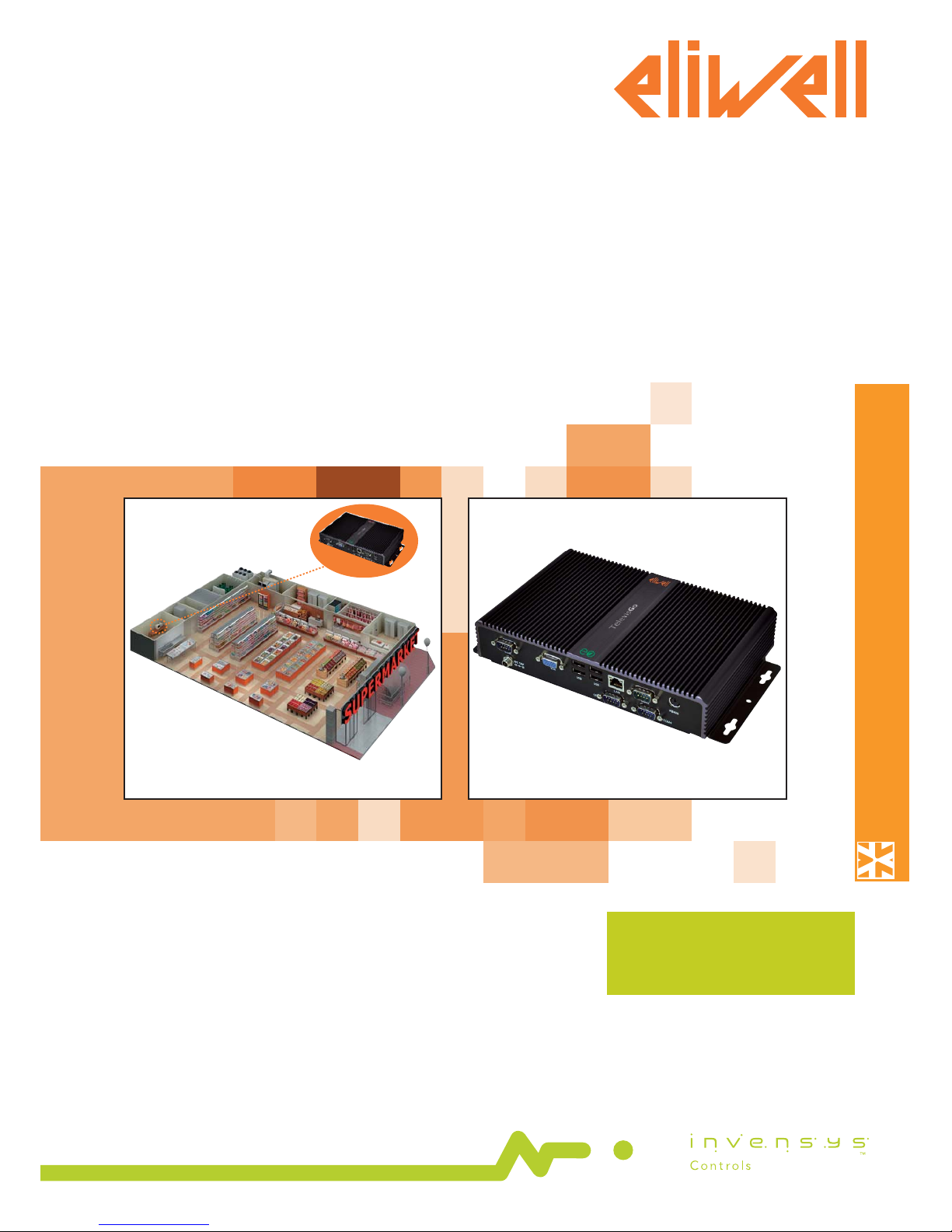
TelevisGo
MANAGEMENT AND MONITORING
Monitoring and control have never been this easy
TelevisGo is a family of devices used to
monitor, control and manage commercial
refrigeration installations from a distance.
USER
MANUAL
Page 2

CONTENTS
1. USING THE MANUAL ........................................................................................... 5
2. INTRODUCTION .................................................................................................. 6
2.1 GENERAL DESCRIPTION ................................................................................................................................................6
2.2 FEATURES/MODELS .......................................................................................................................................................6
2.2.1 INTERFACE .....................................................................................................................................................................................................................................6
2.2.2 SPECIFICATIONS AND REGULATORY FRAMEWORK ...........................................................................................................................................................6
2.2.3 REGULATIONS ...............................................................................................................................................................................................................................6
2.2.3.1 Compatibility with EN12830 standard ................................................................................................................................................................................6
2.2.3.2 Application information sheet ..............................................................................................................................................................................................7
2.2.4 LANGUAGES SUPPORTED .........................................................................................................................................................................................................7
2.3 COMPATIBILITY ................................................................................................................................................................7
2.3.1 BROWSERS SUPPORTED ............................................................................................................................................................................................................7
2.3.2 TYPES OF NETWORK THAT CAN MONITORED .....................................................................................................................................................................7
2.3.3 COMPATIBLE MODEMS ..............................................................................................................................................................................................................8
2.3.4 RANGES OF DEVICES SUPPORTED ..........................................................................................................................................................................................8
2.4 DISCLAIMER AND PC CONFIGURATION ...................................................................................................................8
2.5 ACCESSORIES AVAILABLE ............................................................................................................................................9
2.6 SOFTWARE TOOLS ........................................................................................................................................................9
3. MECHANICAL INSTALLATION .......................................................................... 10
3.1 GENERAL WARNINGS ................................................................................................................................................. 10
3.2 PACKAGE CONTENTS ................................................................................................................................................. 10
3.3 MECHANICAL INSTALLATION ................................................................................................................................... 10
3.4 CONNECTIONS ON THE DEVICE ............................................................................................................................. 10
3.4.1 CONFIGURING NETWORK DEVICES .................................................................................................................................................................................... 11
3.4.2 RS-485 CONNECTION .............................................................................................................................................................................................................. 11
3.4.3 LAN-ADAPTER CONNECTION ............................................................................................................................................................................................... 12
4. USER INTERFACE ............................................................................................... 13
4.1 LOGIN .............................................................................................................................................................................. 13
4.2 WELCOME PAGE .......................................................................................................................................................... 13
4.3 PAGE STRUCTURE ........................................................................................................................................................ 14
4.4 NAVIGATION MENU .................................................................................................................................................... 14
4.5 STATUS BAR ................................................................................................................................................................... 14
4.6 ACTION/COMMAND ICONS ..................................................................................................................................... 14
4.7 STATUS ICONS .............................................................................................................................................................. 15
5. INSTALLATION / MAINTENANCE ..................................................................... 16
5.1 DEVICE SETTINGS ........................................................................................................................................................ 16
5.1.1 SETTING DATE&TIME ................................................................................................................................................................................................................ 16
5.1.2 ENTERING THE PLANT NAME ................................................................................................................................................................................................. 16
5.1.3 SETTING NETWORK IP/DNS .................................................................................................................................................................................................... 16
5.2 NETWORK SCAN AND DEVICE NAMING ............................................................................................................... 17
5.2.1 DEFINING INTERFACES ............................................................................................................................................................................................................ 17
5.2.2 CONFIGURING THE DEVICE NETWORK .............................................................................................................................................................................. 19
5.2.3 NAMING NETWORK DEVICES MANUALLY OR FROM FILE .............................................................................................................................................. 20
5.2.4 NAMING NETWORK DEVICES FROM FILE ........................................................................................................................................................................... 21
5.2.5 SETTING THE DATA LOGGING INTERVAL ............................................................................................................................................................................ 21
5.2.6 GENERAL SYSTEM SETTINGS ................................................................................................................................................................................................. 22
5.2.7 START LOGGING ........................................................................................................................................................................................................................ 24
Page 3

5.3 MANAGING USER PROFILES / MULTIPLE USERS AND DEFAULT PAGE ........................................................... 24
5.4 SCHEDULED ACTIVITIES ............................................................................................................................................. 26
5.4.1 VIEWING SCHEDULED ACTIVITIES ........................................................................................................................................................................................ 26
5.4.2 ADD, EDIT OR REMOVE SCHEDULED ACTIVITIES ............................................................................................................................................................. 27
5.4.2.1 Details..................................................................................................................................................................................................................................... 27
5.4.2.2 Scheduling ............................................................................................................................................................................................................................ 28
5.4.2.3 Action ..................................................................................................................................................................................................................................... 29
5.4.2.4 Filters ...................................................................................................................................................................................................................................... 30
5.4.3 STARTING SCHEDULED ACTIVITIES ...................................................................................................................................................................................... 33
5.5 ENERGY RESOURCES .................................................................................................................................................. 33
6. ALARM MANAGEMENT .................................................................................... 35
6.1 INTRODUCTION ........................................................................................................................................................... 35
6.2 NEW ALARM ALERT/MESSAGE ................................................................................................................................. 35
6.2.1 SETTING UP/SENDING ALARM MESSAGES ........................................................................................................................................................................ 36
6.2.2 RECIPIENT CONFIGURATION ................................................................................................................................................................................................. 36
6.2.2.1 Summary ................................................................................................................................................................................................................................ 36
6.2.2.2 Alarm categories .................................................................................................................................................................................................................. 36
6.2.2.3 Actions ................................................................................................................................................................................................................................... 38
6.2.2.4 Time intervals ........................................................................................................................................................................................................................ 40
6.2.3 MEDIA CONFIGURATION ........................................................................................................................................................................................................ 42
6.2.3.1 Media Priority ........................................................................................................................................................................................................................ 43
6.2.3.2 Media Settings ...................................................................................................................................................................................................................... 44
7. USER: OPERATION ............................................................................................ 45
7.1 ALARM DISPLAY ............................................................................................................................................................ 45
7.2 DATA DISPLAY ............................................................................................................................................................... 45
7.2.1 REAL TIME DATA ........................................................................................................................................................................................................................ 45
7.2.2 DATA ARCHIVE ........................................................................................................................................................................................................................... 47
7.2.2.1 Data archive graphs ............................................................................................................................................................................................................. 49
7.2.3 ENERGY RESOURCES REPORT ............................................................................................................................................................................................... 51
7.2.4 ENERGY RESOURCES GRAPH ................................................................................................................................................................................................. 51
7.2.5 REAL TIME ALARMS ................................................................................................................................................................................................................... 52
7.2.6 ALARM LOG ................................................................................................................................................................................................................................ 53
7.2.7 DOWNLOAD DATA ................................................................................................................................................................................................................... 54
7.3 NETWORK COMMANDS FOR DEVICES ................................................................................................................. 54
7.3.1 PARAMETERS .............................................................................................................................................................................................................................. 55
7.3.2 RVD ............................................................................................................................................................................................................................................... 56
7.3.3 CHANGING THE LANGUAGE ................................................................................................................................................................................................. 57
8. SYSTEM UPGRADE AND BACKUP METHODS ................................................. 58
8.1 SYSTEM BACKUP AND RESTORE .............................................................................................................................. 60
9. SCHEDULED ACTIONS - ADVANCED SETTINGS .............................................. 61
10. ADVANCED DIAGNOSTICS TOOLS ................................................................ 62
10.1 FILE DOWNLOAD ...................................................................................................................................................... 62
10.2 RESET ADMINISTRATOR PASSWORD.................................................................................................................... 63
11. REMOTE DATA DOWNLOAD PROTOCOL ...................................................... 64
12. FAQS ................................................................................................................ 65
13. WARNINGS ...................................................................................................... 66
Page 4

Page 5
TelevisGo Page 5/68
To allow quick, easy reference, the manual has been designed with the following features:
Important!: Information that the user must be aware of to prevent any damage to the system or hazards to
people, devices, data, etc. Users MUST read and take note of these sections.
Indication/highlighted text: further information on the topic in question that the user should be aware of.
Suggestion: a suggestion that could help the user to understand and make better use of the information provided.
1. USING THE MANUAL
Page 6

TelevisGo Page 6/68
2.1 GENERAL DESCRIPTION
TelevisGo is a range of monitoring, control and remote control devices for commercial refrigeration and air-conditioning
installations.
It features a web-based remote user interface that can be configured from any PC with an internet connection.
TelevisGo records data, manages alarms and provides remote access to network and controller data to easily monitor HACCP data
and schedule maintenance activities.
It features the following connectivity systems:
• Ethernet interface (internal)
• GSM modem (external – see section entitled “Compatibility”).
• USB ports
TelevisGo also offers remote WEB-based access (see section entitled "Compatibility”) without having to install any extra software.
The user interface supports 5 native languages (Italian, English, Spanish, German and French) although additional languages can be
easily installed later.
TelevisGo is a long-lasting, open platform that can be upgraded with new functions and data exchange capabilities with centralized
systems.
It is the ideal solution for industrial refrigeration and air-conditioning applications. Up to 224 controllers and 3000 resources can be
run on one license.
Access to TelevisGo is easy, intuitive and shortens installation and learning times. The advanced user interface can be accessed via
a PC web browser to analyze data and maintain full control over system operation.
As Administrator, all aspects of the system can be fully controlled via remote access (see "Disclaimer and PC Configuration).
2.2 FEATURES/MODELS
2.2.1 INTERFACE
TelevisGo has an advanced user interface that can be accessed via web browser (*) from any personal computer, in order to analyze
data and control all functions of the plant.
(*) A browser is a programme used to navigate web sites; it is normally included with the Operating System
(Windows, Linux, Mac ...) or can be downloaded and installed free.
2.2.2 SPECIFICATIONS AND REGULATORY FRAMEWORK
The main technical features of TelevisGo are listed below:
• Power supply: DC12V with external 100-240 V ±10%, 50-60 Hz supply
• Max. power absorbed: 10 VA
• Working temperature: 0 … 50°C
• Storage temperature: -20 … 60°C
• Operating/storage humidity: 10...90% (non condensing)
• Maximum number of connectable devices: 224
• Operating System: XP Embedded (English language)
(the license number card is inside the packaging)
• Connections: Ethernet (LAN), external GSM modem (see section entitled “Compatibility”) and built-in USB ports.
• Web-based user interface to configure and control local applications from a distance.
• Remote software update (via internet).
• Less energy intensive thanks to the use of high-performance components which significantly boost power output and
lower consumption.
• Recyclable - fully recyclable materials used (packaging, manuals, etc.)
2.2.3 REGULATIONS
The main regulations/directives which TelevisGo complies with are listed below:
• UNI EN 12830:2001 (HACCP)
• 2002/95/EC (RoHS Directive)
2.2.3.1 Compatibility with EN12830 standard
TelevisGo logs temperatures in accordance with the provisions of EN12830 in the following conditions:
• Network devices: Use only class II rated devices (Eliwell)
• Log temperatures using Televis network resources with Eliwell NTC probes
To guarantee compliance with standard EN12830, select data logging for analogue probes ONLY.
A year's worth of data logging is guaranteed for 1500 analogue resources, at intervals of 15 minutes.
The selection of non-analogue resources may affect archiving performance in terms of variations in the time asynchronous resources
have within the network. In this case, refer to the GUI Web archive management section to check the storage capacity of your own
plant and to set the parameters accordingly, to assure they meet the criteria specified by standard EN12830.
2. INTRODUCTION
Page 7

TelevisGo Page 7/68
2.2.3.2 Application information sheet
a) Type of data logging:
Suitable to save to archive.
b) General requirements:
- Measurement range: Network devices: use only class II rated devices (Eliwell)
- Supply voltage and frequency: 12V DC with 100-240 V ±10%, 50-60 Hz ±3Hz power unit
- Power failures: Non-volatile internal memory, 10-year duration
c) Requirements for metrological characteristics:
- Maximum permissible errors, temperature measurement resolution and error:
For network devices: depends on the devices
- Logging interval: configurable (default 15 minutes).
- Logging time: 1 year's worth of data guaranteed for 1500 analogue resources, at logging intervals of 15 minutes
- Maximum relative weather measurement error and weather recording error <0.1%
- Response time: <30' with Eliwell controllers and Eliwell NTC probes
- Climate and influence of ambient temperature: 'type A' in air
- Climate and temperature testing under logger storage and transportation conditions: 'type A' in air
- Electrical disturbances and radiated electromagnetic field susceptibility: conforms to EN55022 and EN55024
2.2.4 LANGUAGES SUPPORTED
The software features the following native languages:
• Italian
• English
• Spanish
• German
• French
Additional languages are available and can be requested from Eliwell.
On approval of the request, these languages can be installed separately.
2.3 COMPATIBILITY
2.3.1 BROWSERS SUPPORTED
TelevisGo is compatible with the following browsers:
• Internet Explorer 7 or later
• Mozilla Firefox 3.5 or later
To speed up navigation:
To make WEB navigation faster and more effective, we recommend:
1) Enabling the browser cache. This means pictures don't have to be reloaded at each connection, making navigation quicker and
more responsive.
IMPORTANT!
Incorrect configuration of the cache could lead to pages not being refreshed properly!
The following settings are recommended:
• Microsoft Internet Explorer:
• Internet Options Window
General Browsing History Settings
• Check for newer versions of stored pages should be set to "Auto".
• Mozilla Firefox:
• Tools window
Advanced Network
• Override automatic cache management must NOT be selected.
NOTE: Clear the cache every time the application has been updated.
2) Use a browser that shows even partially loaded data before the whole page loads, which makes navigation quicker and more
responsive. For networks with over 700 resources, we recommend using browsers with more efficient JavaScript engines, such
as Firefox 3.5 or IE8 or later. This speeds up the introduction of and interaction with pages containing the network hierarchy (e.g.
Archived data selection / Naming / Network Summary / Offline).
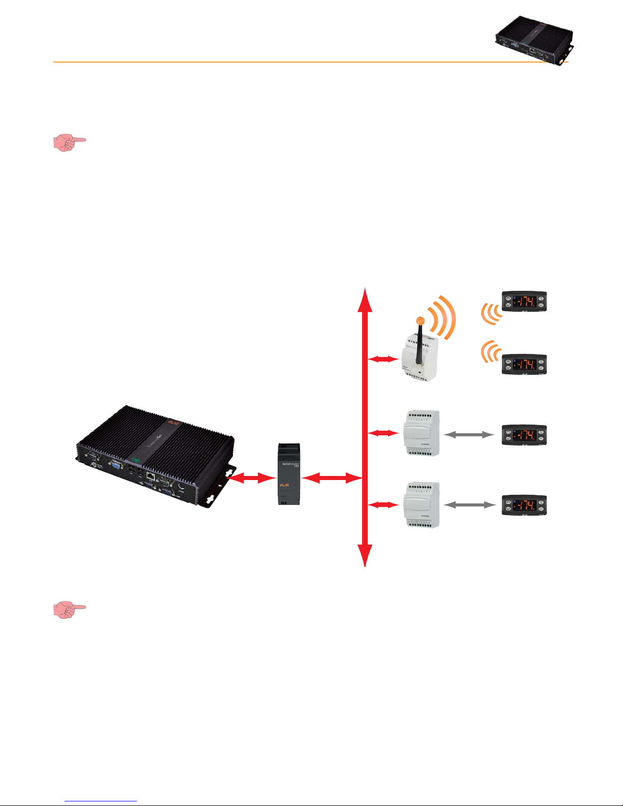
2.3.2 TYPES OF NETWORK THAT CAN MONITORED
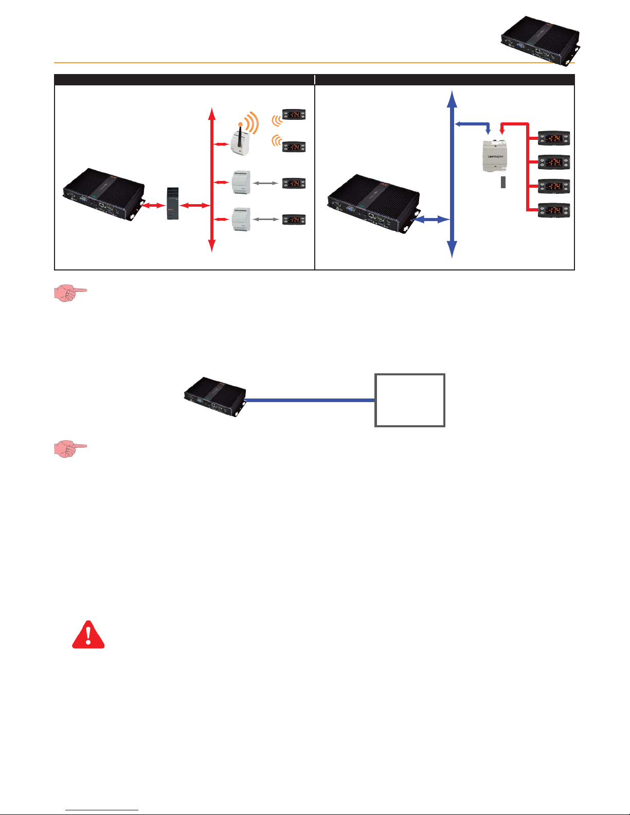
TelevisGo has been approved for the following networks:
• “RS-485” networks and gateways using the SerialAdapter232 module (accessory can be purchased separately).
• “LAN” networks using the TCP/IP and gateways using the LAN Adapter module (accessory can be purchased separately).
The Eliwell guarantee extends to the correct use of only one type of network at a time. Some examples of usable networks are
provided below:
Page 8
TelevisGo Page 8/68
1) Sample RS-485 network 2) Sample TCP/IP network
Bus Adapter
Bus Adapter
Radio Adapter
RS485
uNet
RS485
TCP/IP
100...240 V~
Alimentazione
uNet
Ethernet
RS-485
SerialAdpater232 (picture on left) can only be connected to COM1 or COM2 as it is supplied by them. Other serial
accessories (modems) must be connected to serials COM3 or COM 4.
2.3.3 COMPATIBLE MODEMS
TelevisGo is compatible with RS232-interface GSM modems powered by SIEMENS TC35-type technology.
The GSM modem connection can be done directly via RS232:
RS232RS232
MODEM
(GSM)
N.B.: To ensure it works correctly, the PIN of the modem SIM card must be disabled.
2.3.4 RANGES OF DEVICES SUPPORTED
All devices supported by TelevisGo are listed in the file "Controller_Driver_List.xls” in the "DriverList” directory on the CD
provided. The updated file can also be downloaded from www.eliwell.it.
2.4 DISCLAIMER AND PC CONFIGURATION
Users should be aware of the following:
• The default time zone is GMT+1.
• The default Administrator password is empty (not set); users must enter a password to assure safe and restricted system access.
IMPORTANT!! USERS ARE RESPONSIBLE FOR SAVING AND REMEMBERING THE PASSWORD ENTERED;
ELIWELL HAS NO WAY WHATSOEVER OF RECOVERING A PASSWORD.
• The PC has an FTP server with read and write permission in this folder: C:\Eliwell.
Entry credentials to FTP server:
• User name: Go
• Password: GoZilla
The port used is TCP /IP 21.
NOTE: We recommend modifying the FTP server password.
Page 9

TelevisGo Page 9/68
• Remote access to the PC is possible:
Remote access is achieved via the UltraVNC application working from the TCP/IP 5900 port.
The default access account is:
• User name: TSUser
• Password: TS
To modify the access mode, go to programme properties.
TSUser belongs to the Administrators group in Windows.
Service Default Account TCP/IP ports Connection application
FTP User name: Go
Password: GoZilla
21 Any FTP client
Remote access User name: TSUser
Password: TS
5900 UltraVNC
• Disconnect the USB mass storage device after maintenance is performed. Leaving a USB mass storage device connected
prevents the PC from restarting properly.
IMPORTANT!!
The PC is dedicated exclusively to running the TelevisGo application.
The installation of any other type of application could impair system stability.
The only installation permitted is an anti-virus software.
Users can choose an anti-virus that best suits their protection policy.
Bear in mind however that an anti-virus in action can adversely affect system performance.
Make sure the anti-virus does not block the TCP/UDP ports used by Televis Compact.
2.5 ACCESSORIES AVAILABLE
The following accessories can be provided for the network connection:
• GSM modem: RS232 GSM modem based on SIEMENS type TC35 technology.
• Serial Adapter232: An interface to connect between the TelevisGo RS232 port (COM1 or COM2) and the RS485 network.
• LanAdapter: LanAdapter is an Ethernet /RS-485 interface module that allows communication via LAN between a
monitoring system and a device network.
The LanAdapter supports controller networks with either Micronet/Televis or MODBUS protocol.
• Wifi LanAdapter: Like the LanAdapter but with a WiFi / RS-485 interface.
• BusAdapter Device with a TTL/RS-485 communication interface to connect Eliwell controllers to cabled supervision
and monitoring networks.
• RadioAdapter: Same as a BusAdapter but with wireless interface for connecting TTl/RS-485 networks.
• SmartAdapter: The SmartAdapter is a ModBUS protocol converter for Televis networks. It allows TelevisNet software to
connect to ModBUS protocol devices via an RS-485 interface.
2.6 SOFTWARE TOOLS
OFFLINE CONFIGURATOR
Offline Configurator is a PC application software that configures controller networks offline by defining abstract structured rules.
Users can create configurations to assign names, alarms and scheduled actions to be applied to the network.
The tool can be downloaded from the Eliwell website on completion of second-level registration.
Register at www.eliwell.it and request level 2 access to the confidential area.
Page 10
TelevisGo Page 10/68
3.1 GENERAL WARNINGS
IMPORTANT!
Always make sure the device is switched OFF before touching connections.
All operations must be carried out by qualified personnel.
Do not mount devices in extremely damp and/or dirt-laden areas; they are designed for use in places with ordinary or normal levels
of contamination.
Make sure the area near the cooling slots is ventilated.
The admissible ambient temperature range for correct operation is between –5°C and +40°C.
3.2 PACKAGE CONTENTS
The package contains:
• TelevisGo device
• Power unit and power cable
• CD with manuals, list of compatible devices and examples of how to upgrade device
3.3 MECHANICAL INSTALLATION
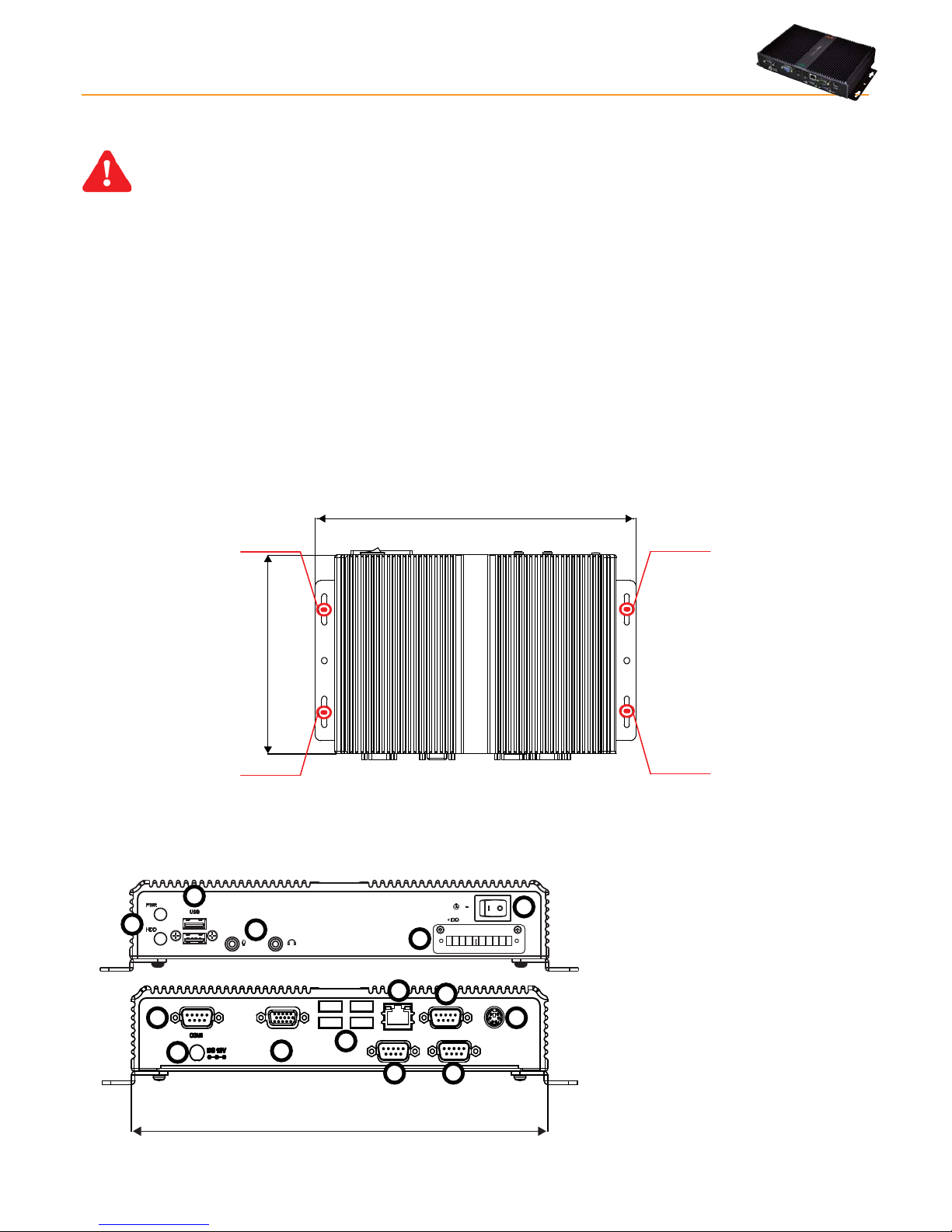
TelevisGo was designed for wall or panel-mounting.
Secure the device to the wall/panel with 4 screws (not supplied) to match the holes illustrated in the figure below.
274.00 mm
155.00 mm
Hole A
Hole C
Hole B
Hole D
3.4 CONNECTIONS ON THE DEVICE
The following connections are to be found on the front and back of the controller:
VGA USB
USB
COM3
LAN
COM2
COM4
KBD
240.00 mm
1) Connection to 12V DC power supply
2) COM1 (RS232) port
3) VGA monitor connection
4) 4 USB connections
5) COM3 (RS485) port
6) COM4 (RS485) port
7) LAN RJ45 connection
8) COM2 (RS232) port
9) PS2 keyboard connection
10) LED power supply and HDU
11) 2 USB connections
12) Audio minijack socket
13) PowerON/powerOFF button
14) Not used
3. MECHANICAL INSTALLATION
Page 11
TelevisGo Page 11/68
Modules and system devices must be connected using a cable with 0.5 mm2 conductors. There must be no more than 2km between
TelevisGo and the last module. Comply with relevant applicable legislation when laying data transmission cables.
Use a shielded cable (i.e. Belden cable model 8762 with PVC sleeve, 2 conductors plus braiding, 20 AWG, nominal capacity
between conductors 89pF, nominal capacity of 161pF between conductor and shielding).
Remember to insert a 120Ω, ¼W resistor between the “+” and “-“ terminals of the last device in the network.
To switch the device off, press and hold button (13) for 4 seconds (to prevent any accidental switching off). In the event of
a blackout, the PC and application restart automatically when mains power is returned.
3.4.1 CONFIGURING NETWORK DEVICES
Before scanning the network with TelevisGo, each device in the network must be assigned a unique address by setting parameters
“FAA” and “dEA”.
3.4.2 RS-485 CONNECTION
An example of a RS-485 network is provided in the figure below.
Bus Adapter
Bus Adapter
Radio Adapter
RS485
uNet
RS485
It features: 1 SerialAdapter232, 2 BusAdapters, 1 RadioAdapter and 4 ID controllers.
The SerialAdpater232 adapter can only be connected to COM1 or COM2 as it is supplied by them.
Other serial accessories (modems) must be connected to serials COM3 or COM4.
Page 12
TelevisGo Page 12/68
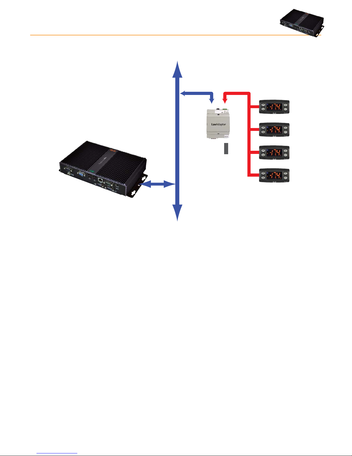
3.4.3 LAN-ADAPTER CONNECTION
The figure below shows a LAN/Ethernet network.
TCP/IP
100...240 V~
Alimentazione
uNet
Ethernet
RS-485
It features: 1 LanAdapter and 4 ID controllers.
NOTE: Signal propagation in an Ethernet network depends on bus traffic, making access times to the LanAdapter non-
deterministic and potentially influencing access time to the RS485 sub-network.
NOTE: If connection proves difficult, check if the right profile has been assigned to the network; if not, modify accordingly (see
section entitled “Interface definition”)
Page 13

TelevisGo Page 13/68
TelevisGo has an advanced user interface that can be accessed via web browser (*) from any personal computer, in order to analyze
data and control all functions of the plant.
(*) A browser is a programme used to navigate web sites; it is normally included with the Operating System
(Windows, Linux, Mac ...); alternatively, it can be downloaded and installed as freeware.
TelevisGo must be switched on and connected to the internet to access the web interface.
Open a compatible browser and enter the device address:
http:// <TelevisGo IP Address>
The factory-set parameters are as follows: <TelevisGo IP Address> = 192.168.50.50 Subnet mask:= 255.255.0.0
To assure the proper function of the PC - TelevisGo connection (Ethernet), the PC must have an IP address configured that is
compatible with the TelevisGo subnet mask (normally the same Subnet mask and IP address, in which only the fourth numerical
block changes to be different for each element in the network).
For more detailed information and special installations, contact the network administrator).
4.1 LOGIN
You must log in before you can access any TelevisGo functions.
The web login page is used to select the user interface language; the application is set by
default to the browser language.
If you are using Internet Explorer for example, you can check the current language by
going to:
Tools > Internet Options > Languages. (button
in Internet Explorer 9)
At the top of the login area there are several TelevisGo status icons:
• Plant name.
• TelevisGo status.
• Data logging status (started, stopped).
• Alarm status (active, acknowledged, sleeping).
For further details on icons, see status icons table.
The default is a predefined user profile (account) with the following credentials:
• User: Administrator
• Password: 0 (zero)
Select the check box "Save this information" and the system will remember the user
name and language selected the next time you log in.
User name:
Plant name:
Televis Go
Versione 5.0.0.0
Password:
User interface language:
Save this info
English
Administrator
Login
TelevisGo
4.2 WELCOME PAGE
TelevisGo
Eliwell Controls
Software version: 5.0.0.0
O.S. version: 5.0.0
Boot loader compatible version: 5.0.0.0
Interface identifier: 0
Page last update on: 7.39.34
Plant identification Networks found
Devices 15
Interface identifier: 999
Devices 1
Device number: 16
60
Maximum number of devices:
Televis Go
Informazioni
Data » Overview
Alarms ComputerSettingsToolsData
Overview Real time table Historical table Historical chart
Energy report Energy chart
4. USER INTERFACE
Page 14
TelevisGo Page 14/68
The welcome page (see picture above) displays information on the current status of the installation:
• Plant name.
• Program version: the program version installed on TelevisGo.
• Networks found: number of devices found for each interface.
4.3 PAGE STRUCTURE
All pages in the web application have the same structure, i.e.:
• Navigation menu at the top.
• Work area in center.
• Status bar at the bottom.
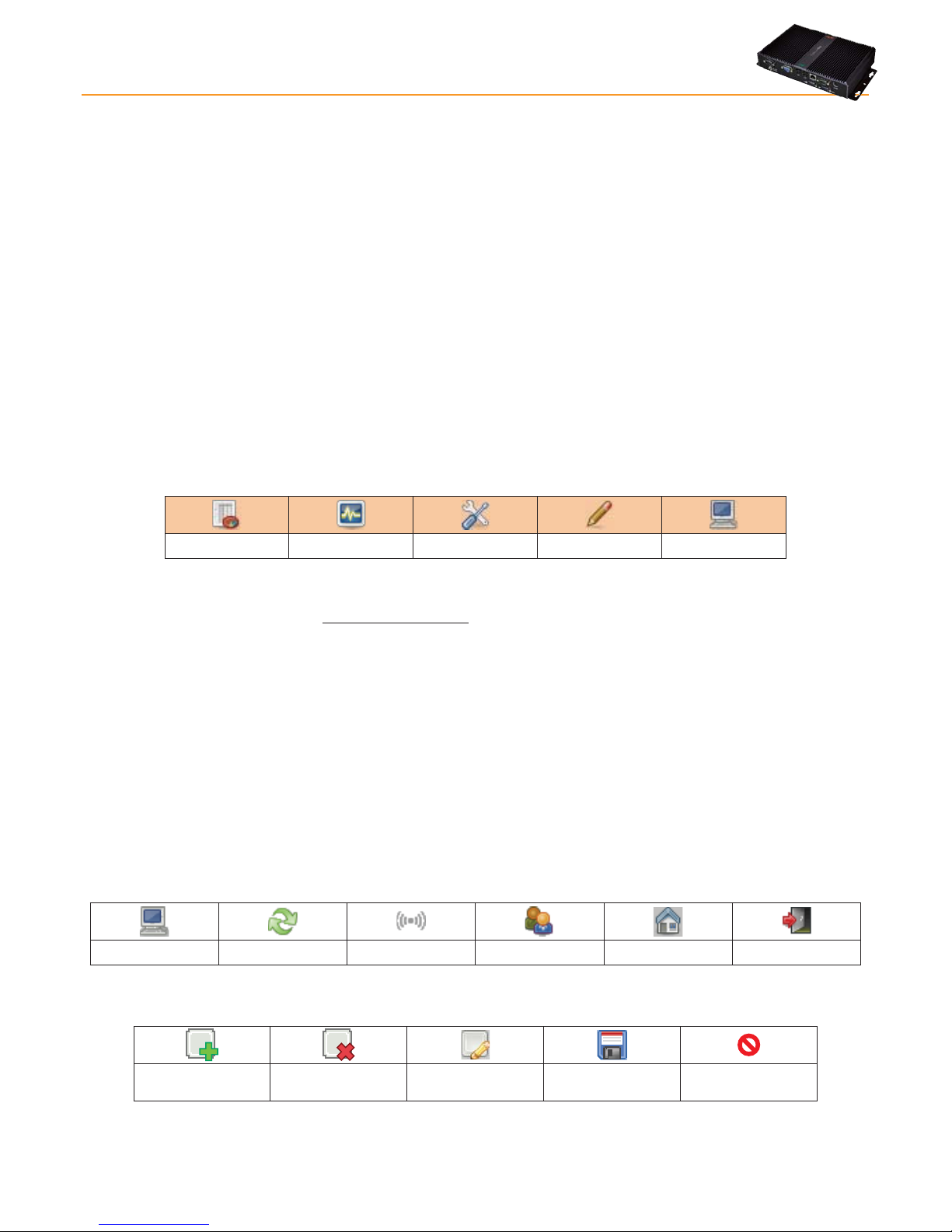
4.4 NAVIGATION MENU
The navigation menu is shown at the top of the page and contains the hypertext links to the different sections of the application:
• Data
• Alarms
• Functions (Tools)
• Settings
• Computer
Data Alarms Functions Settings Computer
Each menu has a number of associated commands listed under the menu bar (sub-menu) (e.g. "general view", "real time table",
"historic table"...).
Clicking a menu changes the sub-menu but not the current page.
Clicking a sub-menu heading changes the current page.
4.5 STATUS BAR
The status bar is always shown at the bottom of the window, providing important information of system status. The Status Bar
contains the following icons and text:
• Plant name
• Data logging: Indicates TelevisGo logging status (running /not running).
• Alarm Status: The icon takes the form of the current alarm status, as described in the icons legend.
• User (Group): indicates the name of the current user. The group of origin is contained in the brackets. Access rights
depend on the group of origin; all users from the same group are given the same access rights.
There are another two icons on the right side of the status bar:
• Welcome page: provides quick access to the welcome page.
• Exit: ends the current session and returns you to the login page.
Plant name Data logging Alarm status User (Group) Welcome page Exit
4.6 ACTION/COMMAND ICONS
Add element
Remove selected
element
Modify selected
element
Save changes Cancel changes
Page 15
TelevisGo Page 15/68
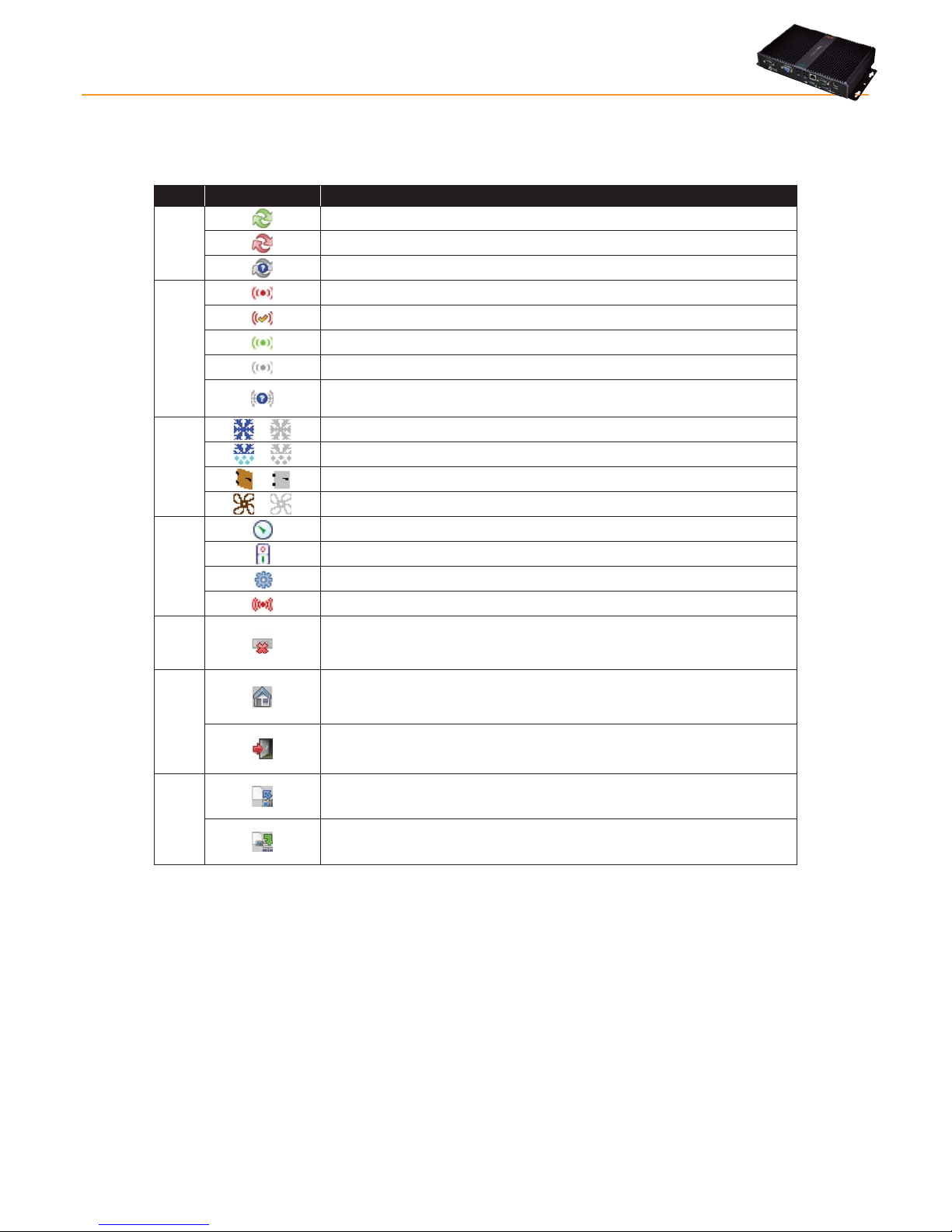
4.7 STATUS ICONS
The user interface has a series of indicator icons giving instant feedback on the status of the resource the icon represents. The icons
appearing in the different pages of the application are listed below, with an explanatory description:
Icon Description
Logging
status
TelevisGo data logging running.
TelevisGo data logging not running.
No controller network configured.
Alarm status
Indicates that the alarm is active.
Indicates that the alarm is active and has been noted by the user.
Indicates that the alarm in question has already ended.
Indicates that the alarm has never been active.
No alarm status information available.
(check status of plant connection and data logging).
Resource status
/
Compressor: On / Off.
/
Defrost: On / Off.
/
Port: Open / Closed.
/
Fans: On / Off.
Inputs and
regulators
Analogue input.
Digital input.
Associated device.
Alarm-type resource.
NO LINK
Nolink: indicates that the device in question cannot be reached.
Access
to the application
Home: return to start page (plant data - welcome page or page specified by
the user).
Exit: disconnects the user from the application and goes back to the login
page display.
Saving
configuration
Save naming: used to save the network naming and alarm delay settings
directly on the TelevisGo device.
Apply naming: used to apply previously saved naming and alarm delay
settings to the current network.
Page 16
TelevisGo Page 16/68
To install TelevisGo, you have to set up the device and the network of devices it is connected to first.
This can be done via the WEB interface.
NOTE1: Before scanning the network with TelevisGo, each device in the network must be assigned a unique address by
setting parameters “FAA” and “dEA” (family:device).
NOTE2: On plugging in, TelevisGo does not switch on immediately as some checks are run automatically and the software
is loaded (takes about 30 seconds).
5.1 DEVICE SETTINGS
5.1.1 SETTING DATE&TIME
To set the plant name and date & time in the device, go to:
Computer Information General
To access this section, data logging must be suspended (see Data Logging section).
In the window that opens, click the
icon or Edit.
Now you can enter the date and time then click the
icon or Save.
The date and time can be imported directly from your computer by clicking the “Use client date/time” button.
Click the
icon or Cancel to exit without saving the changes.
If you change page without saving, any changes made will be lost (the same as clicking Cancel).
IMPORTANT: Changing the date/time may cause your Web session to expire. In this case, you may need to re-connect.
5.1.2 ENTERING THE PLANT NAME
To set the plant name in the device, go to:
Computer Information General
In the window that opens, click the
icon or Edit.
You can now enter the Plant name then click the
icon or Save.
Click the
icon or Cancel to exit without saving the changes.
If you change page without saving, any changes made will be lost (the same as clicking Cancel).
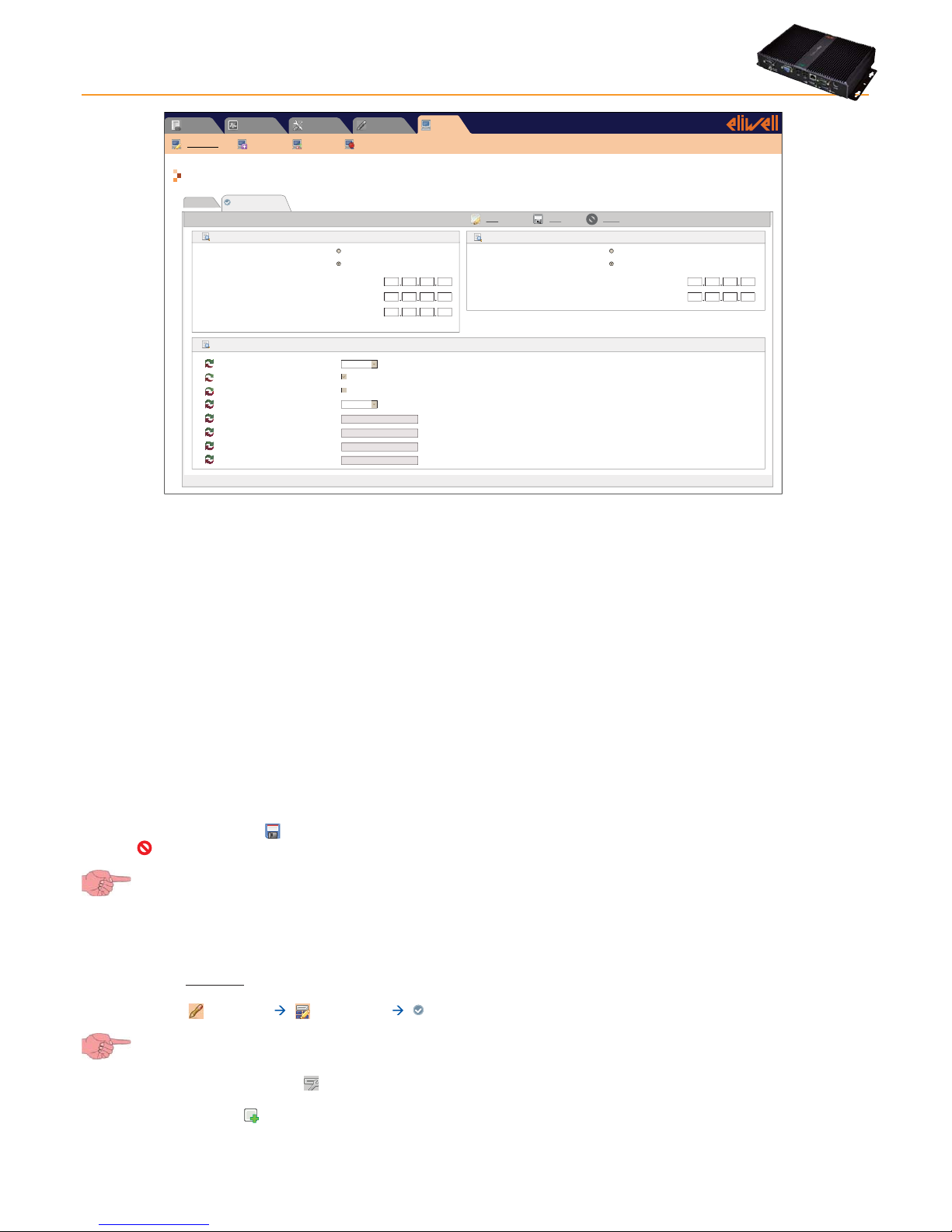
5.1.3 SETTING NETWORK IP/DNS
To set the network IP/DNS, go to:
Computer Information Network Settings
In the window that opens, click the icon or Edit.
5. INSTALLATION / MAINTENANCE
Page 17
TelevisGo Page 17/68
Page last update on: 7.39.34
Computer » Information » Network settings
Alarms Computer
Settings
ToolsData
General
Information
Upgrade Reboot Update license
Network settings
IP Address
Obtain an IP address automatically (DHCP)
Use the following IP adress:
IP Address
Edit Save Cancel
Subnet mask
Gateway
DNS
10 39 4 103
255 255 255 0
Obtain the DNS server IP address automatically
Use the following server DNS addresses:
Preferred DNS server:
Alternate DNS server:
10 39 4 15
10 39 4 16
10 39 4 12
:
Proxy Settings
Proxy - SOCKS - Domain resolution
Proxy - Ignore local addresses
Proxy - Enabled
Proxy - Protocol
Proxy - Server address
Proxy - Server port
Proxy - User
Proxy - Password
Native DNS
SOCKS 5
Depending on the network (contact the network administrator for necessary information), enter the following information:
1) IP address: set if the DHCP (dynamic address) or manual IP (static address) is to be used.
• If the automatic IP has been set, when the device is restarted, it will connect using the values received from the network,
which may vary each time.
• If the manual IP has been set, when the device is switched on, it connects using the same values all the time, which must
be saved in the following order: IP address, Subnet mask and Gateway.
2) DNS address: set if the automatic DNS (dynamic address) or manual DNS is to be used.
3) Proxy Configuration: set proxy server parameters (the system must be restarted after setting these parameters):
• SOCKS - Domain name resolution : native DNS, Proxy or DNS via proxy
• Ignore for local addresses: when selected, TelevisGo will not use the proxy server to resolve addresses within its own
sub-network.
• Enable: select if the SOCKS server requires authentication.
• Protocol version: 4, 4a, 5 or HTTP Proxy
• Server address: IP address of SOCKS server
• Server port: SOCKS server access port
• User: user name for SOCKS server authentication
• Password: password for SOCKS server authentication.
To save data entered, click the
icon or Save.
Click the
icon or Cancel to exit without saving the changes.
If you change page without saving, any changes made will be lost (the same as clicking Cancel).
5.2 NETWORK SCAN AND DEVICE NAMING
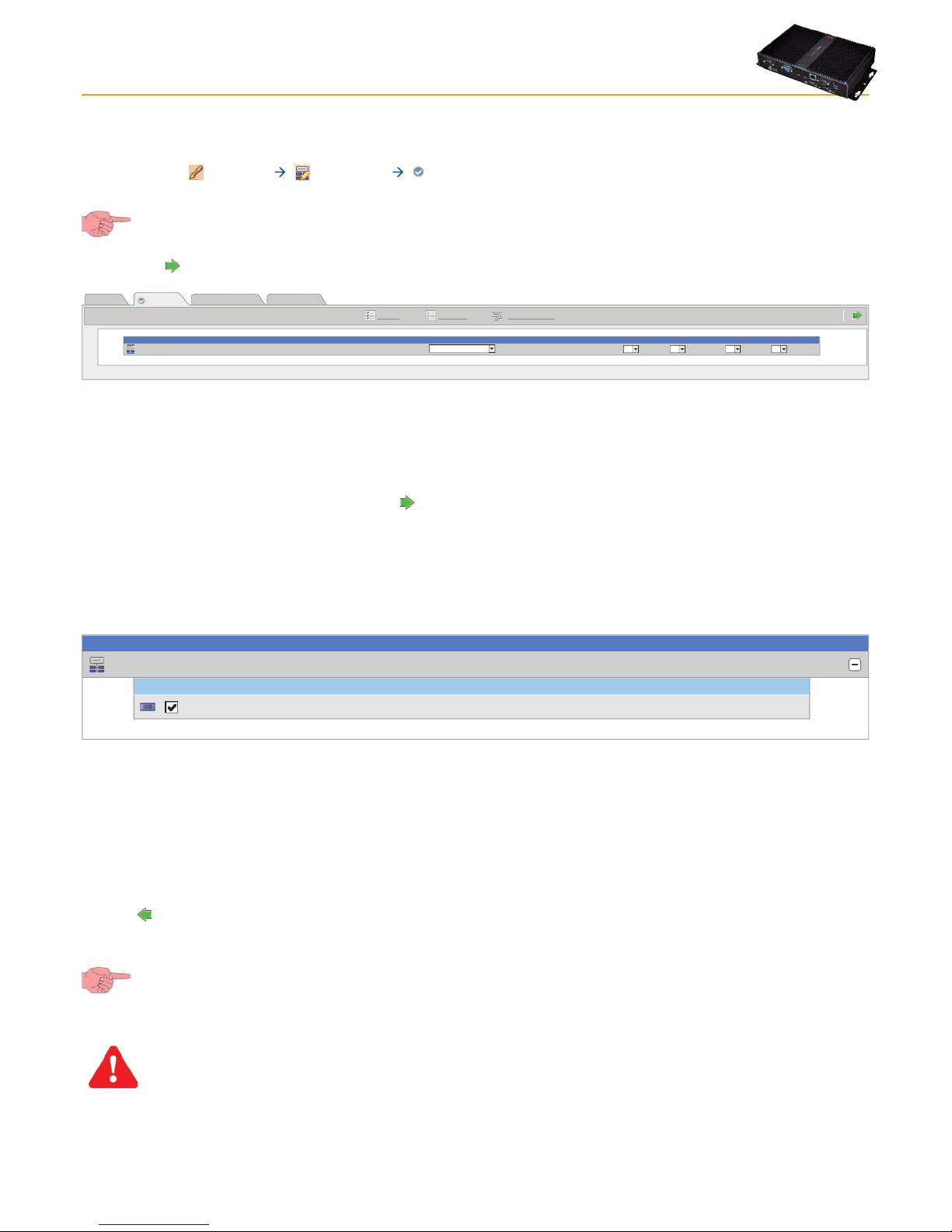
5.2.1 DEFINING INTERFACES
To define system interfaces, go to:
Settings Interfaces Scan
To access this section, data logging must be suspended (see Data Logging section).
In the new page that opens, click the icon or Manage interfaces.
A window will open in which you can enter/edit interfaces.
To add a network, click the
icon or Add, and a screen with the following options will open:
Page 18

TelevisGo Page 18/68
• Interface type: type of network interface:
a) Serial Adapter
b) LanAdapter (TCP/IP)
Serial Adapter (Fig.1) example:
• Port: physical communication port used by TelevisGo (COM)
• Protocol: type of communication protocol.
a) Micronet
b) Mixed & Smart (Micronet with Modbus sub-network after a
SmartAdapter)
c) Mixed native (Micronet and Modbus together)
Lan Adapter example (Fig.2):
• Address: set the device IP address.
• Port: virtual TCP/IP navigation import.
• Protocol: type of communication protocol.
a) Micronet
b) Mixed & Smart (Micronet with Modbus sub-network after a
SmartAdapter)
c) Mixed native (Micronet and Modbus together)
• Fieldbus: types of network available:
a) BusAdapter: RS485 serial network
b) LanAdapter: LAN type network
c) LanAdapter Wifi: LAN network + Wifi
d) LanAdapter Radio: LAN network + RadioAdapter
e) RadioAdapter: RS485 network + RadioAdapter
f) SmartAdapter: RS485 network + SmartAdapter
Fig.1
Interface
type
Fieldbus
Details
SerialAdapter
LanAdapter
Port
Protocol
BusAdapter
Micronet
Fig.2
Interface
type
Fieldbus
Details
SerialAdapter
LanAdapter
Address
Port
Protocol
LanAdapter
Micronet
56789
192 168 1 1
On selection of the icon or Edit, after selecting the network to be modified, the same screen as "Add" opens where you can
change all previously entered values.
Click the
icon or Save to save all data entered or changes made. When using a LANAdapter network, we recommend you always
use the “Test connection” key to check communication between TelevisGo and the device itself.
Click the
icon or Cancel to exit without saving the changes.
To remove a network, select it then click the
icon or Remove.
Click the
icon to go back a menu.
If you change page without saving, any changes made will be lost (the same as clicking Cancel).
Page 19
TelevisGo Page 19/68
5.2.2 CONFIGURING THE DEVICE NETWORK
To set up a network of devices, go to:
Settings Interfaces Scan
To access this section, data logging must be suspended (see Data Logging section).
Now click the
icon. This page opens:
Page last update on: 7.39.34
Select all Deselect all Manage Interfaces
LAN Adapter
Interface
ID Address Fieldbus Discovery range
0
192.168.0.1
From
to
00
LanAdapter 00 14 14
Naming
Out of network
Discovery
View
12 34
A list of all available and previously defined interfaces is displayed (see the Defining Interfaces section) along with associated
settings (name, ID, address....).
Set the scan range using pop up menus 1, 2, 3 and 4.
The default ranges are: 00:00/14:14 for Micronet networks and 00:00/15:15 for Mixed networks.
To start scanning or to find network devices, click the
icon.
NOTE:
Scanning the full range can take a few minutes.
Likewise, it could take even longer if there are any unused addresses (the system makes more than one attempt when it doesn't
receive a reply) or if a Mixed network is being used.
On completion, the following window opens:
LAN Adapter
Interface
Interface
identifier
DevicesAddress
0 192.168.0.1 1
Address Description State
New0 02:00 0.00:00 ID 974LX02:00
A
B
Line A identifies the network scanned. Line B and subsequent lines list devices associated to the network.
The colour of each line has a specific meaning:
• GREEN: new device located in the network
• BLACK: existing network device
• GREY: device not located, part of previous network but possibly no longer present.
• RED: device for which TelevisGo has no internal driver.
On completion, click Save to save all data logged.
Click the
icon to go back a menu.
If you change page without saving, any changes made will be lost (the same as clicking Cancel).
IMPORTANT: in the following circumstances, a second scan must be performed:
• If one or more devices have been added
• If the drivers of one or more TelevisGo controllers have been updated.
• If you have enabled/disabled one or more controller resources by changing some parameters.
• A device changed alarm is displayed.
Page 20
TelevisGo Page 20/68
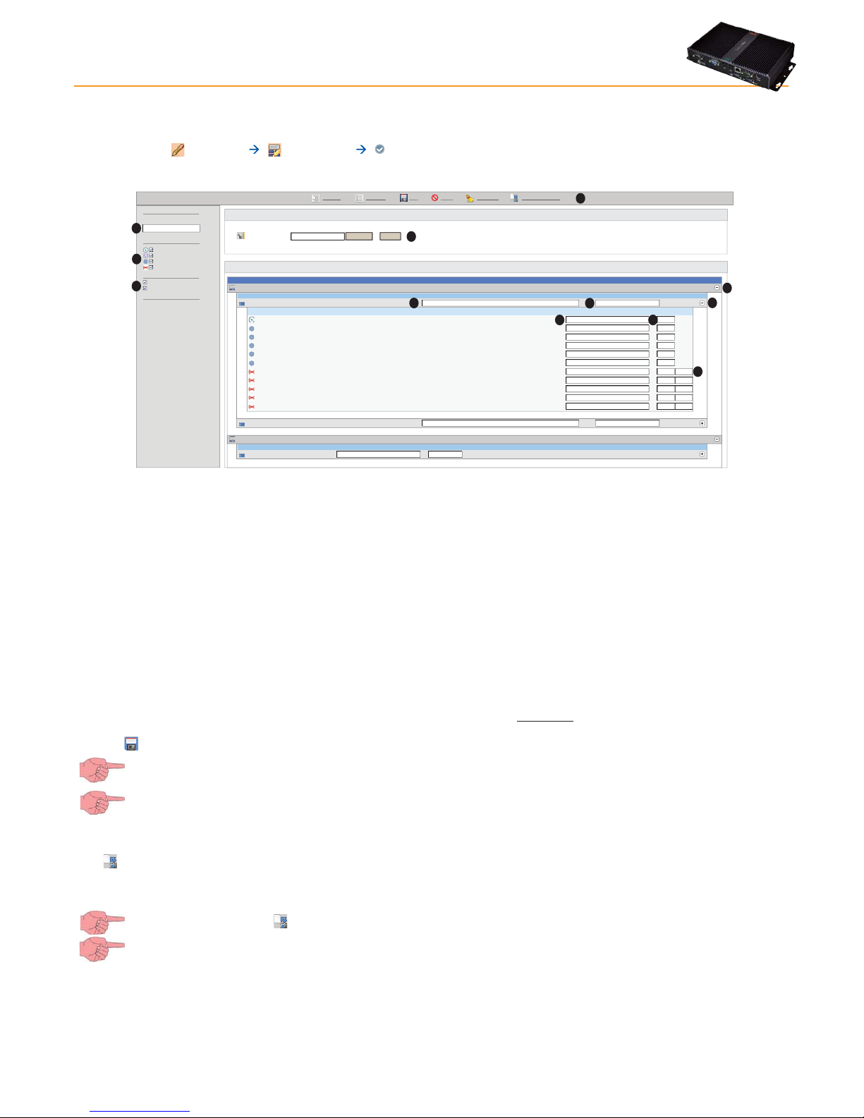
5.2.3 NAMING NETWORK DEVICES MANUALLY OR FROM FILE
To name a network device manually, go to:
Settings Interfaces Naming
The following page opens:
Select devices
Network naming rules
Browse...
Execute
(.xml)
File to be loaded
LAN Adapter
Interface ID DevicesAddress
0
192.168.0.1
15
Name
Alias
Alias (short)
Resources
110.02:00 ID 974LX
Analog input 1
Door
Alarm output
Compressor 1
Defrost 1
Evaporator fans 1
Door open
NOLINK
Analog input fault 1
Exceeded the high Input threshold 1
Exceeded the low Input threshold 1
Nome
Alias
Alias
(short)
Delay
(minutes)
Compact 999 1
Nome Alias Alias (short) Resources
999.14:14 TelevisCompact 7
0
0
0
0
0
0.02:01 ID 974LX
11
A
B
C D
E
G
F
Cancel filtersExpand all Collapse all
Save Cancel
Take naming snapshot
Legend
Filter devices
Description
Filter resources
Analogue inputs
Digital Inputs
States
Alarms
Show helpers
Show table header
Legend
H
I
L
M
N
Devices viewed can be filtered by Description (or part description) (I) or by type via Device Filters (L).
Clicking the Cancel Filters (H) button will reset all filters defined (all device filters enabled).
The table heading and key (M) can be viewed/hidden.
Press button F to expand the list of devices present in the network.
In boxes A and B the device can be associated to an "Extended Name" (A - Alias) and a "Short Name" (B - Short Alias). Both can
be up to 25 characters long. You will need the “Short Name” to manage TXT messages.
Valid characters:
• Upper case (A, B, C, …)
• Lower case (a, b, c, …)
• Numbers (1, 2, 3, …)
• Some special characters (: , - , _ , <space>)
Press button G to expand the list of resources belonging to the device.
In boxes C and D, an "Alias" (C) and a "Alias (short)" (D) can be associated, using the same rules applied to the device Description
and Alias.
If the resource is an alarm, box E opens. The "Delay time" (Tr) before which an alarm will be signaled can be entered in this box (the
alarm doesn't generate an alarm message/alert if it is shorter than the Tr time set (in minutes). This alarm will not be shown in the
alarm screen).
Click the
icon or Save (H) to save all data entered or changes made.
If you change page without saving, any changes made will be lost (the same as clicking Cancel).
N.B.: The devices also include the TelevisGo with all its resources.
There are two icons on the status bar, the function of which is:
•
Capture naming snapshot (H): to save naming settings and network alarm delays in TelevisGo.
Clicking this button opens the file automatically (in .xml format) with the saved settings, allowing users to save a backup
file.
IMPORTANT: using the icon to save settings overwrites any previously saved information.
The browser may issue a warning message asking you to confirm if you want to download the file; this depends on
your browser security settings.
Network devices can be named by applying the settings listed in an xml file generated by the OfflineConfigurator application (see the
associated manual) or saved via the Capture naming snapshot function (H):
• The file and settings to be applied can be selected in the File to load (N) box.
• Clicking Run applies settings to all network devices matching the rules contained in the xml file.
Page 21
TelevisGo Page 21/68
5.2.4 NAMING NETWORK DEVICES FROM FILE
Network devices can be named by applying the settings in a specific xml file generated by the Offline Configurator application (see
the associated manual).
Go to:
Settings Interfaces Device Template
LAN Adapter
Interface ID DevicesAddress
0
192.168.0.1
15
Name
0.02:00 ID 974LX
0.02:01 ID 974LX
Compact 999 1
999.14:14 TelevisCompact
Legend
Filter devices
Description
Filter resources
Analogue inputs
Digital Inputs
States
Alarms
Show helpers
Show table header
Legend
Select devices
Select a device template
Browse...
Execute
(.xml)
File to be loaded
Device template
Select all Deselect all
Expand all
Collapse all Cancel filters Apply
The page is very similar to the one in Naming Network Devices Manually or From File, as regards both the device and associated
functions (for the meaning of many controls).
The file and settings to be applied can be selected in the File to load (A) box.
Clicking Run will load the template and make it available in the drop-down menu (D).
Clicking the Apply (C) button will apply the current template settings (D) to all network devices selected via the check box to the
left of the name (B).
The following buttons are presented at the top:
•
Select All: to select all devices in the list.
•
Deselect All: to deselect all devices in the list.
•
Expand All: to view all devices in the interface.
•
Collapse All: to hide all devices in the interface.
• Cancel Filters: to cancel all filters applied.
5.2.5 SETTING THE DATA LOGGING INTERVAL
A data logging interval must be set. The time set (in minutes) is the interval (sample) in which data from the selected resource will be
logged.
Data on Statuses, Alarms and Digital Inputs is not logged in this interval. In these cases, data is recorded when these parameters
change and not over a set interval. To set the interval, go to:
Settings Data Archive Control
To access this section, data logging must be suspended (see Data Logging section).
On opening this menu, click “Saved data-logging interval in archive”, then click the icon or Edit, enter the number
(hours:minutes:seconds) and click the
icon or Save.
For expert USERS: in
Settings Data Archive Manage
the “Maximum Capacity” (CM) (maximum memory used to save data) is set at 7GB; users can also set the “part of data
archive to be used for circularity” (%CA) (percentage of memory freed when oldest data is deleted each time the
memory reaches full capacity).
The factory-set value is: %CA = 12%.
If you change page without saving, any changes made will be lost (the same as clicking Cancel).
The device will now show the summary in:
Settings Data archive Summary
Page 22

TelevisGo Page 22/68
5.2.6 GENERAL SYSTEM SETTINGS
This menu can be used to set the display language, the communication ports, and alarm alert transmission times. To activate the
menu, go to:
Settings General Settings System
To access these sections, data logging must be suspended (see Data Logging section).
The following page opens:
Page last update on: 7.39.34
Edit
Save
Cancel
Sistema
Alarms
TelevisTwin
Reboot the system in order to make the new settings active.
Languages
System language
Web server - Communication port
Data transfer - Communication port
[1 .. 65535]
[1 .. 65535]
Ports
English
80
8080
Media
In “System” you can set the following
1) LANGUAGES:
• System language: to set the language used for creating the alarm messages and communication with
systems external to TelevisGo (TWIN or third party systems).
2) PORTS:
• Web server - Communication Port: to identify the port to be used for the WEB connection (e.g. 80)
• Data transmission - Communication port: to identify the port to be used to download data (e.g. 8080)
-----------------------------------------------------------------------------------------------------------------------------------------------------------------------------------------The following page is displayed when TelevisTwin is clicked:
Media
Page last update on: 7.39.34
Edit
Save
Cancel
System
Alarms
TelevisTwin
Reboot the system in order to make the new settings active.
Twin - Life test - Sending period
Twin - Life test - Delay on first send
Twin - Life test - Retry interval
Twin - Life test - Retry duration
[0 seconds .. 30 days]
>= 0 seconds
[0 seconds .. 30 days]
[0 seconds .. 30 days]
Sending life test notifications
01:00:00
00:15:00
00:01:00
01:00:00
In “TelevisTwin” you can set the following:
1) LIFE TEST REPORT SENDING:
• Twin - Life test - Sending period: to set how often a life report is sent.
• Twin - Life test - First sending delay: to set how long to wait after switching on before sending a life report.
• Twin - Life test - Retry interval: to set the interval between 2 consecutive life report sending attempts
• Twin - Life test - Retry duration: to set the maximum interval in which to attempt life report sending.
The life test will be sent to TelevisTwin if at least one "TelevisTwin" action is configured within the system (see chapter entitled
"Alarm management").
------------------------------------------------------------------------------------------------------------------------------------------------------------------------------------------
Page 23

TelevisGo Page 23/68
The following page is displayed when Alarms is clicked:
Page last update on: 7.39.34
Edit
Save
Cancel
System
Alarms
TelevisTwin
Reboot the system in order to make the new settings active.
General
sms: +390000000
e-mail - Server - Address
e-mail - Server - Port
e-mail - Server - Sender address
e-mail - Server - Authentication required
e-mail - Account - Name
e-mail - Account - Password
[1 .. 65535]
Copy sender address
Email server configuration
25
SMS alphabet
Modem signal strength lower alarm threshold (%)
[1 .. 100]
SMS
Standard 7 bit
40
Message
Telephone number
Signal strength: Not available
Test utility
Message
Address
Test utility
Test SMS from TelevisComp
+390000000
Test email from TelevisComp
change@email.address
SMS Phone
Email
Alarms - Retry interval
Alarms - Retry duration
[0 seconds .. 30 days]
[0 seconds .. 30 days]
00:01:00
01:00:00
Alarms - Emergency recipient
Media
In “Alarms” you can set the following
1) GENERAL:
• Alarms - Retry interval: to set the interval between 2 consecutive attempts to send an alarm.
(see section entitled “Alarm management”)
• Alarms - Retry duration: to set the maximum interval in which to attempt to send an alarm.
(see section entitled “Alarm management”)
• Alarms - Emergency recipient: to set the telephone number to which an emergency TXT will be sent should
the TelevisGo database becomes corrupted and the recipients set by the user
are no longer available.
2) TXT:
• TXT alphabet: to set the kind of alphabet you want to use when sending TXT messages.
Standard 7 bit (default) or UCS2 or Cyrillic 7 bit.
by default it is set to "7 bit"
• Lower model signal threshold alarm (%): to set the minimum modem signal threshold (as a percentage) which must be
reached before a "Modem signal insufficient" alarm is activated.
3) Email server address configuration:
• Email - Server - Address: to set the email server address.
• Email - Server - Port: to set the email server connection port.
• Email - Server - Sender's address: to set the sender's email address.
• Email - Server - Authentication request: to tell the system whether an authentication request is required
(tick the box if the Server requires authentication).
• Email - Account - Nome: to set the user name (if authentication is required).
• Email - Account - Password: to set the user password (if authentication is required).
The "Media" card is described in the "Alarm Management" section.
Test Utility sections are shown on the right: here users can check instantly if the settings applied are correct and working properly.
Page 24

TelevisGo Page 24/68
5.2.7 START LOGGING
To start data logging, go to:
Functions Start/Stop
On entering the menu, one of the windows shown below will open:
• If data logging is suspended, the window on the left opens: click Start to start logging.
• If data logging is started, the window on the left opens: click Stop to stop logging.
Data acquisition
Start
Acquisition status: Not running
Start
Stop
Data acquisition
Stop
Acquisition status: Running
30
Restart after minutes
In the Restart After box you can set a number in minutes after which data logging restarts automatically after it has been stopped.
Automatically restarting data logging is useful as it will prevent users from accidentally leaving data logging turned off after
stopping it for maintenance of parts of the system.
Data regarding devices and past alarms can only be viewed with data logging turned on.
5.3 MANAGING USER PROFILES / MULTIPLE USERS AND DEFAULT PAGE
To edit a user profile or user group access, go to:
Settings Users Summary
The following window appears:
Groups
Administrators
Groups
Default administrator group
Operators
Default operator group
Users
Default user group
Readers
Default reader group
Administrator
Users
Default administrator
Operator
Default operator
User
Default user
Reader
Default reader
Users
View
Groups
A
B
Page 25

TelevisGo Page 25/68
To create/edit a Group of Users and relative rights, click the Groups (A) icon. The following window appears:
Page last update on: 7.39.34
EditRemove
Add
Save Cancel
View
Users
Groups
Default operator group
Name Description
Default user group
Default reader group
Operators
Users
Enabled
Name*
Description
Permissions
Readers
Groups
Details
Administrators
Default administrator group
Permissions
Application upgrade
Drivers update
License/Languages
upgrade
Network discovery/naming
& start/stop acquisitions
Alarm management
User/group management
Parameter access
Default administrator group
Administrators
The following operations can be performed:
• A user group can be created by clicking the icon or Add.
• Click the
icon or Remove to delete a User Group.
• Click the
icon or Edit to edit a User Group.
• Click the
icon or Save to save the User Group(s) created / edited.
• Click the
icon or Cancel if you don't want to save the changes made to Groups.
If you change page without saving, any changes made will be lost (the same as clicking Cancel).
To create/edit a User and relative profile, click the Users (B) icon. The following window appears:
Ultimo aggiornamento della pagina: 7.39.34
EditRemove
Add
Save Cancel
View
Users
Groups
Default operator group
User name Description
Default user group
Default reader group
Operator
User
Enabled
Group*
User name*
Password
Description
Home Page
Reader
Users
Details
Administrator
Group
Operators
Users
Readers
Administrators
Default administrator group
Default administrator
Alarms state
**************
Administrator
Administrators
The following operations can be performed:
• Click the
icon or Add to create a New User.
• Click the
icon or Remove to delete a User.
• Click the
icon or Edit to edit a User Profile.
• Click the
icon or Save to save the User Profile created/edited.
• Click the
icon or Cancel if you don't want to save the changes made to User Profiles.
If you change page without saving, any changes made will be lost (the same as clicking Cancel).
NOTE:
1) The rights of “Administrators” cannot be modified.
2) To edit the rights of a Group or User Profile, you must be logged in as Administrator or have the necessary authorization
credentials to configure users/groups.
Page 26

TelevisGo Page 26/68
5.4 SCHEDULED ACTIVITIES
TelevisGo can run actions automatically that have been scheduled by users.
There are two types of scheduled activities (or actions):
• Send command to one or more devices.
• Write parameters to one or more devices.
Scheduled activities can have one of three types of frequency:
• Periodical: the action is carried out periodically, with the frequency defined by the user.
• Daily: the action is carried out every n days at one or more times during the day.
• Weekly: the action is carried out every n weeks, on specific days and at one or more times during the day.
Each scheduled event begins at a time set by the user and continues indefinitely with the defined frequency.
The action is therefore performed in accordance with the set schedule. If the action fails, TelevisGo continues to attempt to execute
it at user-defined intervals up to a maximum time, again set by the user. If the maximum duration is set to 0 or if it is less than the reattempt interval, no further attempts will be made.
Scheduled activities can be applied to a selection of devices in the current configuration. The selection is done by applying a userdefined filter to the current network configuration. The result of this filter is the list of devices that the action is to be applied to.
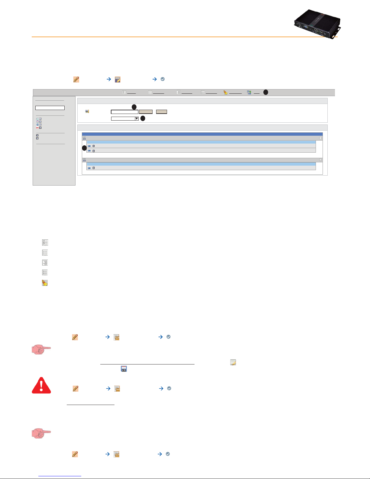
5.4.1 VIEWING SCHEDULED ACTIVITIES
To view the current list of scheduled activities, go to:
Settings Scheduled activities Summary
A window similar to this one will open:
Scheduled actions
Type Name
Description
Schedule
Next
execution
Defrost
Send command: Manual Defrost Every week on Sunday, Wednesday and Saturday at 09.30 31-Jul-11
09.30
7-Jan-11
00.30
5-Jan-11
05.00
and 12.30 (beginning on 31-Jul-11 22.00)
Every 3 days at 00.30 (beginning on 1-Jan-11 11.00)
Every 1 day and 6 hours (beginning on 1-jan-11 11.00)
activation (1 device)
Write parameter map: Map_1.dat
(16 devices)
Write parameters [Set=-2,
HAL=1, LAL=-5] (1 device)
Mappa
Scrittura
Set Point
View
Actions
Page last update on: 4 January 2011 - 15.59.56
In the example, TelevisGo shows three scheduled actions plus a description of each. The columns in the table contain the following
information:
• Type represents the type of action; send command (
) or write parameters ( ).
• Name is a user-defined label.
• Description describes the activity that will be performed; the number of devices it will be applied to is given in brackets.
• Scheduled describes when/how often the activity will happen.
• Next executed on states the next day/time the activity will be performed.
Page 27

TelevisGo Page 27/68
5.4.2 ADD, EDIT OR REMOVE SCHEDULED ACTIVITIES
To edit scheduled activities, go to:
Settings Scheduled Activities Actions
To access these sections, data logging must be suspended (see Data Logging section)
A window similar to this one will open:
PreviewCancelSaveEditRemoveAdd
View
Actions
Actions
Defrost
Scrittura
Mappa
Set Point
Details
Name
Starting
date
Retry
duration
Retry
interval
Name
Type
Schedule
Action
Typ e
Period
Command
Typ e
Command
Periodico
Manual defrost activation
Filters
Language
Deutsch
Edit
The section of the left of the screen contains a list of actions currently defined by the user which can each be selected. The part on
the right gives details of the action selected and the option of modifying it. You now have the following options:
• Click the
icon or Add to create a new scheduled action.
• Select an action and click the icon or Remove to delete the selected action.
• Select an action and click the
icon or Edit to modify the selected action.
• Click the
icon or Save to save an action that has been edited or created.
• Click the
icon or Cancel to delete any changed made to an action.
• Select an action or click the
icon or Preview to open another window in the browser showing a preview of the tools
that the selected action will be applied to.
If you change page without saving, any changes made will be lost (the same as clicking Cancel).
The part on the right is split into 4 sections:
5.4.2.1 Details
The Details tab includes information shared by all types of actions and scheduling:
• The name of the action, as given by the user.
• The start date (and time) of the scheduled action.
• Retry duration.
• Retry interval.
Name
Starting date
Retry duration
Retry interval
Details
00:02:00
01:00:00
01-08-2001 @ 00:00
Defrost
Page 28

TelevisGo Page 28/68
5.4.2.2 Scheduling
The scheduling section allows you to define the type of scheduling (periodical, daily or weekly).
Type
Period
Schedule
Periodic
01.06:00:00
Type
Period
Execution times
Schedule
Daily
3
03:00
Time
Type
Period
Week
Execution
times
Schedule
Weekly
1
09:30
12:30
Sunday
Monday
Tuesday
Wednesday
Thursday
Friday
Saturday
Time
Action performed
every 1 day + 6 hours
(30 hours)
Action performed
every three days at 03.00
Action performed
every Sunday, Wednesday and Saturday at
09.30 and 12.30. 12:30
In periodical scheduling, users must define an interval of time between two subsequent scheduled events.
• To define the interval of time, click the Period box, set the interval in the text box that opens, then click OK.
This type of event will be carried out for the first time at the time set in the Start date box in the Details section.
In daily scheduling, users must define the frequency with which the action should be performed and also at what time of day.
• Enter every how many days the action should be carried out in the Period box. If 0 is entered, on saving TelevisGo will
automatically insert a 1.
• To set a time(s) to carry out the action, click the Execute At box, enter the time in the window that opens, click OK then
.
The time will be added to the list below.
• To delete a time added to the list, click the
button. If you remove the last time in the list, TelevisGo will automatically
add 01:00 to the list.
This type of event will be carried out at the first available time at the date/time set in the Start date box in the Details section.
In weekly scheduling, users must define every how many weeks the action should be performed and also on what days and at what
time of the day.
• Enter every how many weeks the action should be carried out in the Period box. If 0 is entered, on saving TelevisGo will
automatically insert a 1.
• To set the days of the week the action should be performed on, select one or more days in the Week list. If no day is
selected, on saving TelevisGo will automatically select Sunday.
• To set a time(s) to carry out the action, click the Execute At box, enter the time in the window that opens, click OK then
.
The time will be added to the list below.
• To delete a time added to the list, click the
button. If you remove the last time in the list, TelevisGo will automatically
added 01:00 to the list.
This type of event will be carried out on the first available day and at the first available time after the date/time set in the Start date
box in the Details section.
Page 29

TelevisGo Page 29/68
5.4.2.3 Action
The Action section allows you to set the Type of action to be performed.
Type
Command
Action
Command
Manual defrost activation
Manual defrost activation
Lock keyboard
Unlock keyboard
A command type action specifies the command to be applied to the
selected devices (see below).
The command drop-down menu lists all commands for all devices
currently included in the network configuration.
Type
Type
File name
Action
Parameter writing
Parameter map
Map_1.dat
A write parameters (parameter map) action requests the file map name
to be applied each time the action is performed.
The file name must be specified in the File Name box.
To make sure TelevisGo successfully performs the operation, the file
map must be loaded from the system update page (see section entitled
"System Update Modes").
Type
Type
Parameters
Action
Parameter writing
Parameters
Set
HAL
LAL
-2
1
-5
Label
Value
Label Value
For write parameter type actions, the list of parameters to be written and
their associated values must be entered manually. At least one parameter
must be entered.
To enter a new parameter, write the label name in the Label box, the value
in the Value box then click the
button. The label/value pair will be
added to the list below.
If there is a ??? label, TelevisGo will remove it from the list as soon as a
new pair is added.
If a pair already exists with the same label, TelevisGo will overwrite the
previously inserted value.
To remove a previously inserted label/value pair from the list, click the
button. If you remove the last parameter in the list, TelevisGo will
automatically add a ???/??? pair.
Important! TelevisGo distinguishes between upper and lower
case in label names.
Page 30

TelevisGo Page 30/68
5.4.2.4 Filters
The Filters section shows the structure of the current filter.
Language
Filters
English
Edit
Type=analog
Name=*2*
Address=00:0?
ID=0
Selector
Resource
Device
Interface
Example of filter
This filter selects all analogue resources with a "2" (* is a jolly
character) in their Italian name and belonging to devices with
addresses from 00:00 to 00:09 (? is a jolly character), and which
are part of the interface with ID 0.
A filter is applied hierarchically to the network configuration. The purpose of the filter is to make a single, smaller selection from a
specific configuration.
This is done by defining rules for the properties of interfaces, devices and resources. Since some of these properties refer to the
translated names of resources, the Language the filter must use in selecting resources must be specified.
To edit the filter, click the Modify button. A window similar to this one will open:
Filters
Selector
Device Address=”00:0?”
Resource Name=”*2*” Type=”analog”
Interface ID=”0”
Add selectorFilters
Save
Cancel
The filter can be modified from this window. The selection and rule hierarchy is shown on the left. The icons beside each line have
the following meanings:
Page 31

TelevisGo Page 31/68
Icon Meaning
Move the selector up a position.
Move the selector down a position.
Add a child rule (selector > interface; interface > device;device> resource)
Modify selector or rule
Delete selector or rule and all sub-rules.
A filter consists of at least one selector. Each selector identifies a specific sub-group of resources and can be additive or subtractive.
An additive selector adds the resources it has filtered to the final assembly whereas a subtractive selector removes the resources it
has filtered. Selector order is therefore significant. A subtractive filter only makes sense when used to filter the result of the additive
filter before it.
To modify a selector, click the relative
icon. The following box opens on the right of the screen:
Resources
Type
Filter
Add
Analog
Digital
State
Alarm
Save
The Type can have add (additive selector) or remove (subtractive
selector) values.
A selector also allows you to quickly select all Resources in the current
configuration that belong to one or more types of resource.
Once all changes have been made to selector properties, click Save.
To create a rule at the network interface level, click the
icon for the selector that you want to add the rule to. To modify the
properties, click the
icon of the rule you have just created. The following boxes opens on the right of the screen:
Value
Attribute
Quick
Name
ID
Save
Filter
S
et value
--- Select ---
The Filter (below) has two attributes that can be used to define the rule.
The ID field filters interfaces by their identification number. It only
accepts combinations of numbers and ? (question mark) and * (asterisk)
jolly characters.
The Name field filters interfaces by their name. It only accepts special
character combinations which are:
• An IP address with jolly characters (192.168.*.*)
• In the format COMxxx where xxx is a combination of numbers and
jolly characters (COM?)
• The 'Logical' text (the logical interface of TelevisGo).
The Rapid (top) box allows you to set the two ID and Name attributes
by selecting values on the basis of the interfaces present in the current
configuration.
Select the Attribute you want to assign a value to, select a value from
those listed, then click the Set Value key. The field in the Filter area will
assume this value.
Once all changes have been made to selector properties, click Save.
To create a rule at the device level, click the
icon for the interface rule that you want to add the rule to. To modify the properties,
click the
icon of the rule you have just created. The following boxes opens on the right of the screen:
Page 32

TelevisGo Page 32/68
Interface
Value
Attribute
Quick
Name
Model
Address
Save
Filter
S
et valu
e
--- Select ---
--- Select ---
The Filter (below) has three attributes that can be used to define the
rule.
The Address field filters devices by their address. It only accepts
combinations of numbers and ? (question mark) and * (asterisk) jolly
characters, separated by a semi-colon (00:00, 00:*, 9:1?).
The Model field filters devices by model type. Jolly characters ?
(question mark) and * (asterisk) can be used.
The Name field filters devices by their name. Jolly characters ?
(question mark) and * (asterisk) can be used.
The Rapid (top) box allows you to set the three Address, Model and
Name attributes by selecting values on the basis of the devices listed
for the current configuration.
Select the Attribute you want to assign a value to, select an Interface
from those listed for the configuration, select a value from those listed,
then click the Set Value key. The field in the Filter area will assume this
value.
Once all changes have been made to selector properties, click Save.
To create a rule at the resource level, click the
icon for the device rule that you want to add the rule to. To modify the properties,
click the
icon of the rule you have just created. The following boxes opens on the right of the screen:
Type:
Name
ID
Filter
All
Save
The Filter has three attributes that can be used to define the rule.
The ID field filters resources by their identification number. It only
accepts specific combinations of characters, numbers and ? (question
mark) and * (asterisk) jolly characters. The ID of a resource consists of 3
upper case letters, 5 numbers followed by a hyphen or other text. For
example: INP40001-1, ALM00300.
The Name field filters resources by their name translated in the
language selected in the previous step. Jolly characters ? (question
mark) and * (asterisk) can be used.
The Type field filters resources by type (all, analogue only, digital only,
status only, alarms only).
Once all changes have been made to selector properties, click Save.
NOTE:
1) The jolly character ? (question mark) can be any character.
2) The jolly character * (asterisk) can be any sequence of 0 or more characters.
3) A filter selects a group of resources on the basis of defined rules. The scheduled action is applied to all devices that the filtered
resources belong to.
4) A selector with no interface rules and no selected resource type will select all resources in the current configuration.
Once you have defined a filter, click the
icon (or Save) to save it, or the icon (or Cancel) to delete it.
In both cases, you will be returned to the previous screen.
If you change page without saving, any changes made will be lost (the same as clicking Cancel).
Page 33

TelevisGo Page 33/68
5.4.3 STARTING SCHEDULED ACTIVITIES
To Start scheduled activities as scheduled, go to:
Functions Start/Stop
Depending on whether activities have commenced, when you enter this menu one of the windows shown below will open:
• If data logging is suspended, the window on the left opens: click Start to start logging.
• If data logging is started, the window on the left opens: click Stop to stop logging.
Scheduler
Start
Scheduled actions status:
Not running
Start
Stop
Scheduler
Stop
Scheduled actions status:
Running
5.5 ENERGY RESOURCES
TelevisGo allows you to treat the resources of some devices as energy utilities, i.e. measuring the electricity consumption of a plant.
The measurements recorded by these resources will be saved in a dedicated database that is separate from the one with saved
historical data, and with a separate data logging interval.
To set up energy resources, go to:
Settings Interfaces Energy Resources
NOTE: If the page is not shown, reduce your browser zoom.
To access these sections, data logging must be suspended (see Data Logging section).
Page 34

TelevisGo Page 34/68
A window like this will open:
Select all Deselect all Expand all Collapse all Save Cancel Cancel filters
Filter resources
Analog Inputs
Digital Inputs
States
Alarms
Analog input 1
- 15 Devices
Registration interval:
Analog input 2
0.00:00 ID 974/A LX 2
LanAdapterWiFi (192.168.0.1)
Arrangement
3 Columns
Analog input 1
01:00:00
Analog input 2
0.00:08 ID 974/A LX 2
0.00:02 ID 974/A LX 2
0.00:03 ID 974/A LX 2
0.00:04 ID 974/A LX 2
0.00:01 ID 974/A LX 2
0.00:05 ID 974/A LX 2
0.00:06 ID 974/A LX 2
0.00:09 ID 974/A LX 2
0.00:07 ID 974/A LX 2
Analog input 1
Analog input 2
0.00:13 ID 974/A LX 2
0.00:10 ID 974/A LX 2
0.00:11 ID 974/A LX 2
0.00:14 ID 974/A LX 2
0.00:12 ID 974/A LX 2
A
B
C
D
E
F
The page will show the analogue resources of all recognized Modbus devices (F). If there are no Modbus devices, this page would
be empty.
To mark a resource as an energy resource, click the relative check box (to the left of the name) (D). To mark all resources of a device,
click the device check box (D).
The
and buttons either collapse and expand individual devices to hide or show associated resources.
To set the data logging time period of energy resources, click the data-logging interval box (C), set the interval in the text box that
opens, then click OK. The interval must be more than 15 minutes.
The number of columns to display (A) can be defined and the resources filtered (B).
The following buttons are presented at the top:
•
Select All: to select all devices in the list.
•
Deselect All: to deselect all devices in the list.
•
Expand All: to view the resources of all devices in the list.
•
Collapse All: to hide the resources of all devices in the list.
•
Save: to save settings entered.
•
Cancel: to cancel all settings entered.
•
Cancel Filters: to go back to default filter properties, with all resources selected.
If you change page without saving, any changes made will be lost (the same as clicking Cancel).
Page 35

TelevisGo Page 35/68
6. ALARM MANAGEMENT
6.1 INTRODUCTION
Il TelevisGo can display, save and send the alarm situation in all devices connected to the network (e.g. high temperature alarm) to
a group of recipients.
When an alarm is detected, the
symbol lights up (if not already on due to a previous alarm).
The alarm log lists all recent "network" alarms saved in non-volatile memory.
Alarms are recorded as soon as an alarm condition is detected.
IMPORTANT: Network alarms are only detected when TelevisGo data logging is running!
6.2 NEW ALARM ALERT/MESSAGE
TelevisGo sends an alarm alert to all correctly configured and enabled recipients.
Alarm management is controlled through alarm categories which associate device alarms to a series of actions within specific time
intervals.
The methods used by TelevisGo to send alarms are represented in the following flow chart:
START
Alarm
event
Alarm Management
as per the actions
provided from
lower-level categories
END
YES
NO
END
YES
NO
Escalate
ag?
END
NO
YES
Level1
Alarm Management
as per the actions
provided from
higher-level categories
Belongs to
one or more valid
categories
Page 36

TelevisGo Page 36/68
6.2.1 SETTING UP/SENDING ALARM MESSAGES
All switches to alarm condition are recorded, except for when a delay time has been set up and the alarm itself did not persist for
longer than the time set in the delay.
This delay time can be set in the configuration panel for network devices (see section entitled Installation/Maintenance - “Naming
Network Devices Manually or from File”):
from here you can pick which alarms should be signaled and when.
If the list of recipients has been defined, when an error condition arises TelevisGo will store it and send a message in accordance
with the rules established in the relative section (see the "Recipient Configuration" section).
6.2.2 RECIPIENT CONFIGURATION
6.2.2.1 SUMMARY
To view the alarm categories, go to:
Settings Alarms Summary
All "Alarm categories" entered will be displayed. The following page opens:
Page last update on: 7.39.34
Actions
Alarm categories
Time intervals
View
Alarm categories
Level
1
Escalate Name
Universal
SMS - Technical Support
Daily (MON/0.00 > SUN/23.59)
Actions
Time intervals
6.2.2.2 ALARM CATEGORIES
To set the alarm categories, go to:
Settings Alarms Alarm Categories
To access this section, data logging must be suspended (see Data Logging section).
A window like this will open:
Page last update on: 7.39.34
EditRemove
Add
Save Cancel Preview
View
Time intervals
Actions
Alarm categories
Name Level
Alarm categories
universal
1
Details
Actions and Time intervals
Filters
Name*
Enabled
Actions Time intervals
Devices Alarms
SMS - Installer A Always
Daily
SMS - Technical Support
Email - Technical Support
<inferiore id=”0”>
<device address=”02:00”/>
<device address=”02:01”/>
<interface/>
<resource id=”ALM00166”/>
<resource id=”ALM00300”/>
<resource id=”ALM00301”/>
Level: 1
Escalate
Select all Get from list...Select all Get from list...
A
B1
B2
B
C
D
E
F
G
H
All "Alarm Categories" set will be shown in the box on the left (F).
Page 37

TelevisGo Page 37/68
The following commands are presented at the top (E):
• Add or
: To add a new action.
• Remove or
: To remove an action saved previously.
• Edit or
: To modify an action saved previously.
• Save or : To save changes made.
• Cancel or
: To cancel changes made.
• Preview or : To open a new page listing all devices associated with the filters.
Click Add (
) or Edit ( ) to activate the right-hand part of the window; you will be able to enter all interaction details involving
actions, intervals, alarms and devices. Click Save or
to save the new alarm category, click Cancel or to exit without saving.
If you change page without saving, any changes made will be lost (the same as clicking Cancel).
The following controls will be visible:
• Name* : to set the name to be assigned to the alarm category (G)
• Enabled: to enable/disable the "Alarm Category" (H)
• Scale: to enable or disable the checking of higher levels (H)
•
: to establish whether the following have been selected in box C:
ALL =
(all devices selected)
SELECT =
(specific devices selected)
•
: to establish whether the following have been selected in box D:
ALL =
(all alarms selected)
SELECT =
(specific alarms selected)
• level: depending on the content of boxes C and D, an alarm category is assigned a level from 1 to 4.
The following 4 levels can be assigned:
Level Box C Box D
Level 1 All All
Level 2 All Select
Level 3 Select All
Level 4 Select Select
In the event of an Alarm, the system will check whether it is managed, on which device it occurred, whether it belongs to a valid
category and if it was activated during a valid interval. If all conditions have occurred, the actions set in the valid alarm categories
will take place in accordance with a level-based system.
TelevisGo always and exclusively takes valid categories into account, and always begins at the lowest-level categories (level 4).
If there are several categories at the same level, the device will perform them all.
Once the Level 4 category actions are complete (if applicable), if at least one Level 4 category has the "Scale" box (H) selected, the
system will check for higher-level categories and carry out the procedures as required.
The same applies to the other levels.
NOTE: 1) If the "Scale" box has not been selected, the device will only carry out the category procedures for the level
reached.
2) If the "Scale" box has been selected in a Level 4 category but there are no valid Level 3 or Level 2
categories, just Level 1 categories, the system will move directly on to the highest level.
Depending on the box in which data is being entered, the following information is required:
A - Actions:
The box displays a list of actions set previously (see paragraph entitled "Actions").
Actions to be performed can be selected using the corresponding boxes on the left-hand side.
B -Time intervals:
The box displays a list of time intervals set previously (see paragraph entitled "Time intervals").
"Valid to/from" intervals for the alarm category can be selected using the corresponding boxes on the left-hand side.
C - Devices:
The window can be used to select one of the following device options:
• ALL: Select all network devices.
• SELECT: Select one or more specific devices. At this point, save the changes by clicking Save or
; a translation of the
selection in XML language will appear in box B1.
Click Cancel or
to cancel the changes made.
Page 38

TelevisGo Page 38/68
D - Alarms:
The window can be used to select one of the following alarm options:
• ALL: Select all network alarms.
• SELECT: Select one or more specific alarms. At this point, save the changes by clicking Save or
; a translation of the
selection in XML language will appear in box B2.
Click Cancel or
to cancel the changes made.
IMPORTANT: If several time intervals are associated with the same category, the whole group is taken into
account.
If you change page without saving, any changes made will be lost (the same as clicking Cancel).
6.2.2.3 ACTIONS
To set the actions to be performed in the event of an alarm, go to:
Settings Alarms Actions
To access this section, data logging must be suspended (see Data Logging section).
A window like this will open:
Page last update on: 7.39.34
EditRemove
Add
Save Cancel
View Alarm categories Time intervals
Actions
Relay 1
Name Settings
+393337679978
0.02:01
Keyboard Locked and
Keyboard Unlocked
B
C
D
Actions
A
192.168.0.1:5900
Type:
Name
Address
Address 1
Address 2
SMS
Port
Port
Port
Details
TelevisTwin
Enabled
Signal strength: 37%
Send test SMS
Phone Call
A
B
C
D
E
All "Actions" set will be shown in the box on the left (A).
The following commands are presented at the top (E):
• Add or
: To add a new action.
• Remove or : To remove an action saved previously.
• Edit or
: To modify an action saved previously.
• Save or : To save changes made.
• Cancel or
: To cancel changes made.
Click Add (
) or Edit ( ) to activate the right-hand part of the window; you will be able to enter all details of actions. Click Save or
to save the new action, click Cancel or to exit without saving.
If you change page without saving, any changes made will be lost (the same as clicking Cancel).
The Enabled (B) check box enables or disables the action (disabled actions will not be performed by the system).
Page 39

TelevisGo Page 39/68
6 different types of action may be created:
• TelevisTwin: Enter the IP addresses of a TelevisTwin to which any alarm messages should be sent.
• Email: Enter an email address to which any alarm messages should be sent.
• TXT via modem: Enter the telephone number you want TXT messages to go to in the event of an alarm.
• Telephone call: Enter the telephone number you want to call in the event of an alarm.
• Commands: Set the commands to be sent to one or more devices in the event of an alarm.
• Relays: Set the condition of the 2 relays in the event of an alarm.
The types of controls presented (D) depends on the selection made from the drop-down menu (C).
IMPORTANT: Actions are only active when entered in an alarm category.
Depending on the type of action selected, the following windows open:
A - TelevisTwin B - Email C - TXT via modem
Type:
Name
Address
Address 1
Address 2
SMS
Port
Port
Port
Details
TelevisTwin
Enabled
Signal strength: 37%
Send test SMS
Phone Call
+393337600000
192.168.0.23 8080
Type:
Name
Email address
Details
Email
Enabled
Send test email
eliwell@invensys.com
Type:
Name
Telephone number
Details
SMS via Modem
Enabled
Signal strength: 37%
Send test SMS
Make test phone call
+393337600000
D - Telephone call E - Commands
Type:
Name
Telephone number
Details
Phone Call
Enabled
Signal strength: 37%
+393337600000
Send test SMS
Make test phone call
Type:
Name
Device
Command
Command on activating alarm
Command on inactivating alarm
Command
Details
Commands
0.02:00 ID 974LX
Keyboard Locked
Keyboard Unlocked
Enabled
Once all selections have been made, click Save ( ) to save changes made, or Cancel ( ) to cancel them.
If you change page without saving, any changes made will be lost (the same as clicking Cancel).
A - TelevisTwin:
• Name: To enter the name assigned to the action.
• Address: To enter the main IP address of the device (e.g.: 192.168.0.23) and the corresponding port (e.g.: 8080).
• Address 1: To enter an alternative IP address 1 and the corresponding port.
• Address 2: To enter an alternative IP address 2 and the corresponding port.
• TXT: To enter the telephone number you want TXT messages to go to (e.g. +39 333 7600000).
• Signal strength: To establish the signal strength of the modem connected to TelevisGo (as a percentage).
B - Email:
• Name: To enter the name assigned to the action.
• Email: To enter the email address to which alarm alerts should be sent to.
• Send test email To see if the settings entered are correct (the system tries to send an email to the address
provided).
C - TXT via modem:
• Name: To enter the name assigned to the action.
• Telephone number: To enter the telephone number you want TXT messages to go to (e.g. +39 333 7600000).
• Signal strength: To establish the signal strength of the modem connected to TelevisGo (as a percentage).
• Send test SMS To see if the settings entered are correct (the system tries to send a TXT message to the number
provided).
Page 40

TelevisGo Page 40/68
D - Telephone call:
• Name: To enter the name assigned to the action.
• Telephone number: To enter the telephone number to be called (e.g.: +39 333 7600000).
• Signal strength: To establish the signal strength of the modem connected to TelevisGo (as a percentage).
• Test phone call To see if the settings entered are correct (the system tries to call the number provided).
E - Commands:
• Name To enter the name assigned to the action.
• Type: To identify which device in the network to be targeted.
• Command on alarm activated: To establish what the device has to do if an alarm is activated.
• Command on disabled alarm: To establish what the device has to do after an alarm has been deactivated.
IMPORTANT: always add the recipient's international dialing code before the phone number (for phone calls and TXT
messages). (e.g.: for Italy, enter +39).
6.2.2.4 TIME INTERVALS
To set the alarm operation time intervals, go to:
Settings Alarms Time Intervals
To access these sections, data logging must be suspended (see Data Logging section).
A window like this will open:
Page last update on: 7.39.34
EditRemove
Add
Save Cancel
View
Alarm categories
Actions
Time intervals
Name Settings
Time intervals
P1
from Monday at 00:00 to Sunday at 23:59
Details
Name*
Type:
>
01 00 01 00
Daily
A
B
C
D
All intervals set will be shown in the box on the left (A).
The following commands are presented at the top (C):
• Add or
: To add a new interval.
• Remove or
: To remove an interval saved previously.
• Edit or
: To modify an interval saved previously.
• Save or
: To save changes made.
• Cancel or
: To cancel changes made.
Click Add (
) or Edit ( ) to activate the right-hand part of the window; you will be able to enter all details of time intervals. Click
Save or
to save the new time interval, click Cancel or to exit without saving.
If you change page without saving, any changes made will be lost (the same as clicking Cancel).
Page 41

TelevisGo Page 41/68
3 different types of time interval can be created:
• Daily: the interval defined will be applied daily.
• Weekly: the interval defined will be applied weekly.
• Monthly: the interval defined will be applied monthly.
The types of controls presented (D) depends on the selection made from the drop-down menu (B).
Depending on the type of interval selected, the following windows open:
A - Daily B - Weekly C - Monthly
Name*
Type:
Details
>
08 00 19 00
Daily
Name*
Type:
Details
>
>
17 00
08 00
Weekly Continuous
Monday
Friday
Continuous
Periodic
Name*
Type:
Details
>
>
18 30
08 00
Monthly Continuous
01
31
Continuous
Periodic
A - Daily time period:
• Name: To enter the name assigned to the interval.
• Interval: The 2 boxes are used to set the valid from and to times, which apply every day.
(example: 8.00 > 19.00 indicates from 8am to 7pm
19.00 > 6.00 indicates from 7pm to 6am the following day)
B - Weekly time period:
• Name: To enter the name assigned to the interval.
• Period: Here you should set:
• the days of the week involved (from -> to)
• the time period involved (from -> to) on each day
• Continuous: Here you should set:
• the day of the week and the start time
• the day of the week and the end time
OFF
hours
ON
OFF
hours
ON
Periodic
interval
Continuous
interval
MON TUE WED THU FRI MON TUE WED THU FRI
MON TUE WED THU FRI MON TUE WED THU FRI
817817817817817 817817817817817
817 817 817 817 817 817 817 817 817 817
Settings: Monday > Friday
08:00 > 17:00
Settings: Monday @ 08:00
Friday @ 17:00
C - Monthly time period:
• Name: To enter the name assigned to the interval.
• Period: Here you should set:
• the days of the month involved (from -> to)
• the time period involved (from -> to) on each day
• Continuous: Here you should set:
• the day of the month and the start time
• the day of the month and the end time
Page 42

TelevisGo Page 42/68
OFF
hours
ON
OFF
hours
ON
Periodic
interval
Continuous
interval
12345 12345
1234512345
817817817817817 817817817817817
817 817 817 817 817 817 817 817 817 817
Settings: 1 > 5
08:00 > 17:00
Settings: 1 @ 08:00
5 @ 17:00
IMPORTANT: The "CONSTANT" time interval is pre-set as part of the system and cannot be deleted
(it selects 24 hours for all days of the week).
6.2.3 MEDIA CONFIGURATION
TelevisGo automatically detects all compatible connectivity devices it is connected to (such as a LAN network or GSM modem for
example). TelevisGo can use these devices (media) to send alarm alerts.
To view media devices detected and assign priorities to them, go to:
Settings General Settings Media
To access these sections, data logging must be suspended (see Data Logging section).
On clicking Modify, the following screen opens:
System TelevisTwin Alarms
Media
Reboot the system in order to make the new settings active.
Detected Media
Ethernet Broadcom 440x 10/100 Integrated Controller
Telephone
PSTN Dial Up
Mobile phone
GSM Dial UP
GPRS Dial Up
SMS
Type Details Detected
Edit Save Cancel
Scan Peripherals
The Media Found box lists all elements located and the type of connection. The Located column indicates if the medium specified
was found or not, and a description is provided in the Details columns.
On clicking Scan peripheral devices, the system starts scanning for media devices connected to TelevisGo.
Page 43

TelevisGo Page 43/68
6.2.3.1 MEDIA PRIORITY
TelevisGo has a backup mechanism for alarm messages sent.
From this page, you can decide in which order the system should sent alerts in.
e-mail - Primary Medium
e-mail - Secondary Medium
e-mail - Priority
Ethernet
GSM Dial Up
GSM Dial Up
None
PSTN Dial Up
GPRS Dial Up
Ethernet
For example, in the Priority Email box, the primary medium to send alarm alerts via email to can be selected (Ethernet in the
example provided). If there is no Ethernet connection, TelevisGo will try to send the email using the secondary medium (a GSM
modem in this case).
Phonecall - Primary Medium
Phonecall - Secondary Medium
Phonecall - Priority
Mobile pho
None
Mobile phone
Telephone
None
The order of priority for phone call alarm messages is established in the same way.
In both cases, the drop-down menus list all media found for the type of message, even if the specific one is not currently enabled.
Page 44

TelevisGo Page 44/68
6.2.3.2 MEDIA SETTINGS
PSTN, GSM and GPRS connections can also be made from this page.
Each of the three types of connection can be activated from the associated check box.
For PSTN and GSM connections, the following must be entered:
• Number of telephone provider with country code (for example, +39 for Italy)
• User of dial up connection, and
• Password of user for the dial up connection.
Enable PSTN Dial Up
PSTN Provider number
PSTN Username
PSTN Password
PSTN Dial Up Details
Test utility
Test connection
Enable GSM Dial Up
GSM Provider number
GSM Username
GSM password
GSM Dial Up Details
Test utility
Test connection
For GPRS connections, the service Access Point Name (APN) is required (e.g. internet.mnc012.mcc345.gprs).
Enable GPRS Dial Up
GPRS APN
GPRS Dial Up Details
Test utility
Test connection
Page 45

TelevisGo Page 45/68
Using the simple, intuitive interfaces, users can view data and/or alarms in real time, explore the data archive/alarm log, view
graphs and download all data viewed.
IMPORTANT: Network alarms and real-time data are only detected when TelevisGo data logging is running!
7.1 ALARM DISPLAY
All switches to alarm condition are recorded, except for when a delay time has been set up and the alarm itself did not persist for
longer than the time set in the delay.
7.2 DATA DISPLAY
There are two ways of viewing data recorded by network devices:
• Real-time data
• Historical data
7.2.1 REAL TIME DATA
To view real time data, go to:
Data Real Time Table
The following screen opens:
Analog input 1
Door
Alarm output
Compressor 1
Defrost 1
Evaporator fans 1
-3276,8 °C
Closed
Active
Inactive
Active
Inactive
0.02:00 ID 974LX
B
C
D
A
Arrangement
Legend
Selection filters
Description
Resource
Analog
input
Digital
input
States
Compressor
Defrost
Fan
Por t
Select the resources
Apply
1 Column
LanAdapterWiFi (192.168.0.1)
E
Compact
- 2 Devices
- 1 Device
Modem signal strength
Relay 1
Relay 2
* * %
Inactive
Inactive
999.14:14 TelevisCompact
Analog input 1
Door
Alarm output
Compressor 1
Defrost 1
Evaporator fans 1
-3276,8 °C
Closed
Active
Inactive
Active
Inactive
0.03:00 ID 974LX
This page is similar to the Televis one, and can only be accessed when data logging is running.
You can filter by:
• Controller name (B)
• Type of resource (C)
Devices are grouped by interface; users can distribute the list over 1, 2, 3, 4 or 5 columns using the drop-down menu (A).
7. USER: OPERATION
Page 46

TelevisGo Page 46/68
The four icons at the device name level (E) represent the 4 basic statuses and are always shown:
• Compressor status (
)
• Fan status (
)
• Defrost status (
)
• Door open status ( )
If they are grey, it means the resource is switched off, whereas other colors mean they are active. They are NOT shown in the list
below.
The list of relative resources is shown below the device.
If they are grey, it means the resource is switched off or not available for a particular device, whereas other colors mean they are
active. They are NOT shown as resources (B).
If there is only one resource in a specific category, the resource is shown as an icon on the same line as the device and omitted from
the list of resources.
Clicking the button hides/shows the list of resources for each device.
The following buttons are presented at the top:
•
Expand All: to view the resources of all devices in the list.
•
Collapse All: to hide the resources of all devices in the list.
•
Cancel Filters: to go back to default filter properties, with all resources selected.
A key is provided in the bottom left giving the meanings of icons.
Page 47

TelevisGo Page 47/68
7.2.2 DATA ARCHIVE
Logged data can be viewed in table format in the various ways described below. To open or view the page, go to:
Data Historical Data
The following screen opens:
Profile
Quick
Custom
Last hour
--- New profile ---
Select Profile Default
Select a relative range (Quick) or absolute range (Custom). In the
former case, there is a series of preset intervals that start counting
backwards from the current date (by 1, 2, 3, 6, 12 hours, 1 or 2 days). In
the latter case, the start/stop date/time must be specified.
NOTE: The first time you use this function, there are no default profiles.
If a profile has been selected, click
to go straight to the data presentation page (step 3); otherwise, you will be taken to the next
page (step 2).
Click
to go to the next page. The next screen is structured as outlined below:
A
B
C
D
E
F
Page last update on: 7.39.34
Select all
Deselect all Expand all Collapse all
ID
Profile
New profile
Last hour
From
21/07/2010 15.38.59
to
21/07/2010 15.38.59
1 From18/06/2010 17.43.18
Time intervals
1 Network configurations
Show analogs only
Number of records to show
Undersampling
Filter resources
Analog Inputs
Digital Inputs
States
Alarms
Analog input 1
Door state
Alarm output
Compressor 1
Defrost 1
Evaporator fans 1
0.02:00 ID 974LX
.0. LanAdapterWiFi (192.168.0.1)
999 Compact
- 2 devices
- 1 device
Modem signal strength
Relay 1
Relay 2
Compressor 1
Defrost 1
Evaporator fans 1
999.14:14 TelevisCompact
Analog input 1
Door state
Alarm output
Compressor 1
Defrost 1
Evaporator fans 1
0.03:00 ID 974LX
Arrangement
2 Columns
G
The functions of each part of the interface are:
• (A) Layout, to choose a display with 1, 2, 3, 4 or 5 columns.
• (A) Profile, identifies the name of the profile selected (if it is new, the profile type is specified).
• (C) Time intervals, identifies the time interval set for the display.
• (C) Network configurations, identifies the number of network configurations present and since when.
• (E) Resource Filters, shows/hides analogue and digital resources, statuses and/or alarms.
• (D) Sub-sample, when enabled using the check box and when the number of records to view has been specified (n), sub-
samples the number of records present by the selected interval (C) (see NOTE under “Sub-sampling function").
• (G) list of network devices / resources. All resources can be selected/deselected when deciding which data to view/
download.
Clicking the
button hides/shows the list of resources for each device.
Page 48

TelevisGo Page 48/68
The following buttons are presented at the top:
•
Select All: Select all devices in the list.
•
Deselect All: Deselect all devices in the list.
•
Expand All: to view the resources of all devices in the list.
•
Collapse All: to hide the resources of all devices in the list.
N.B.: Sub-sampling function
The Sub-sampling function can be summarized as follows: the system examines the extent of the interval to
be analyzed, divides it into n sub-intervals (where n is the number of records set in section F) and displays 1
record for each of the sub-intervals.
Only analogue resources are shown.
Even if selected using other filters, any other resources are not shown.
Select devices (and associated resources as applicable) to capture data from using the check boxes to the left of the name, then
click to go to the next page. This screen displays the data selected:
14.31.32 41,7 1 1 0 1 0 1 10 101001 1
14.32.32 41,7 1 1 0 1 0 1 10 101001 1
14.33.32 41,7 1 1 0 1 0 1 10 101001 1
14.34.32 41,7 1 1 0 1 0 1 10 101001 1
14.35.32 41,7 1 1 0 0 1 0 01 0
010 01 0
01001 1
14.36.32 41,7 1 1 0 0 1 0 01 001001 1
14.37.32 41,7 1 1 0 0 1 0 01 001001 1
14.38.32 41,7 1 1 0 0 1 0 01 001001 1
14.39.32 41,7 1 1 0 0 1 0 01 001001 1
14.40.32 41,7 1 1 0 0 1 0 01 001001 1
14.41.32 41,7 1 1 0 0 1 0 01 001001 1
17.08.09 41,7 1 1 0 1 0 1 10 101001 1
17.09.09 41,7 1 1 0 1 0 1 10 101001 1
17.19.34 41,7 1 1 0 1 0 1 10 101001 1
17.20.46
17.20.18
17.20.01
14.35.15
17.08.03
17.08.03
17.20.52 41,7
1
101 01 10 101001 1
Plant power off
Acquisitions running
Acquisitions running
Acquisitions stopped
System time change: -1 hour
Export
Profile
Modified
parameters
Device
state
Keyboard
enabling
Defrosting
status
Reduced
set-point
Forced
ventilation
Out
1
Auxiliary
Out2Out
3
Compressor Fans
Fruit island 1
Light Alarm Buzzer
Analog
input
1 (°C)
Time of
09/06/2009
The first column identifies the date/time the data was saved, then the next few columns list the previously selected resources with
the values recorded for each device.
• The
icon allows you to expand variations of asynchronous resources (statuses and digital inputs).
• The
icon allows you to collapse variations of asynchronous resources (statuses and digital inputs).
Four lines with a colored background may also be shown:
• RED background: establishes the time during which data logging was stopped (Logging stopped).
• GREEN background: establishes the time during which data logging took place (Logging in progress).
• YELLOW background: establishes when the time was changed (Time change).
• GREY background: establishes the timescale of a power off period or a power supply failure (Plant blackout).
To export the data displayed, click the
icon or Export. The application will save data in a Csv file (which can be viewed in an
electronic spreadsheet like Microsoft Excel) in a user-defined PC.
To save the profile and make it available to retrieve later, click the
icon or Profile.
Page 49

TelevisGo Page 49/68
7.2.2.1 Data archive graphs
IMPORTANT: To view graphs, you need to install Adobe Flash player version 10.0.x or later. This plug-in can be
downloaded as freeware from the Adobe website (www.adobe.com)
Logged data can be viewed in table format in the various ways described below. To view the page, go to:
Data Historical graph
The following screen opens:
Profile
Quick
Custom
Last hour
--- New profile ---
Select Profile Default
Select a relative range (Quick) or absolute range (Customized). In the
former case, there is a series of preset intervals that start counting
backwards from the current date (by 1, 2, 3, 6, 12 hours, 1 or 2 days). In
the latter case, the start/stop date/time must be specified.
If a profile has been selected, click
to go straight to the data presentation page (step 3); otherwise, you will be taken to the next
page (step 2).
Click
to go to the next page. The next screen is structured as outlined below:
A
B
C
D
E
F
Page last update on: 7.39.34
Select all
Deselect all Expand all Collapse all
ID
Profile
New profile
Last hour
From
21/07/2010 15.38.59
to
21/07/2010 15.38.59
1 From18/06/2010 17.43.18
Time intervals
1 Network configurations
Show analogs only
Number of records to show
Undersampling
Filter resources
Analog Inputs
Digital Inputs
States
Alarms
Analog input 1
Door state
Alarm output
Compressor 1
Defrost 1
Evaporator fans 1
0.02:00 ID 974LX
.0. LanAdapterWiFi (192.168.0.1)
999 Compact
- 2 devices
- 1 device
Modem signal strength
Relay 1
Relay 2
Compressor 1
Defrost 1
Evaporator fans 1
999.14:14 TelevisCompact
Analog input 1
Door state
Alarm output
Compressor 1
Defrost 1
Evaporator fans 1
0.03:00 ID 974LX
Arrangement
2 Columns
G
The page layout and functions of each button are as specified in the Data Archive section, which you are referred to.
Select devices (and associated resources as applicable) to capture data from using the check boxes to the left of the name, then
click to go to the next page.
The page will show the selected data in a graph:
Page 50

TelevisGo Page 50/68
16:50 16:55 17:00
16:53:07
16:45
16:45 16:50
16:55
17:00
50
60
70
80
Device state
Analog input 1: 84,1 %RH Analog input 2: 86,1 %RH Analog Input 3: 57,4 %RHAnalog:
Custom: 09-06-2009 16:42:53 09-06-2009 17:04:51
Snap ><
Zoom:
Export image Print image Profile
Last year Max1 Hour 1 Day6 Hours
The curve showing how recordings (y-axis) varied over time (x-axis).
In particular, there is a line for each resource selected, showing trends in values over time: note that there is a label on the left (e.g.
0.10.09 ID 985LX Compressor 1) which highlights:
• Device ID (e.g.: 0.10.09)
• Device ID (e.g.: ID 985LX)
• Resource name (e.g.: Compressor 1)
By definition, digital resources have only 2 statuses and are therefore represented by a bar:
• Colored bar: resource was active
• Plain bar: resource was inactive
The dots along trend lines indicate sample intervals for historical data.
The graph shown is interactive:
Moving the mouse along the lines of each resource, the pointer will change to a
; the values for the resource at that particular
point in time will be shown at the top (top right).
Analogue:
Analogue input 1: 84.1 %RH Analogue input 2: 86.1 %RH Analogue input 3: 57.4 %RH
Each type of resource is shown in a different color; the resource can be shown/hidden by clicking on a box at the top.
Drag the hand to move back or forward in the time interval shown.
Zoom
Selection boxes to select a specific time band to display are at the bottom right.
1 hour
6 hours
Up to
1 day Last year
• 1 hour: shows graphs for the last hour in the previously selected time interval (step 1).
• 6 hours: shows graphs for the last 6 hours in the previously selected time interval (step 1).
• 1 day: shows graphs for the last day in the previously selected time interval (step 1).
• Last year: shows graphs for the last year in the previously selected time interval (step 1).
• Max: shows graphs for the entire interval selected (step 1).
A custom interval can be selected on the left.
The custom interval can be modified by dragging cursors
at the bottom.
The Add selection box allows you to set the start the time interval on the day shown from 00:00 to 23:59 on the same day.
The < and > arrows move you back and forward in the 24 hour time interval.
Play Function
The
button is on the bottom left: when you click the graph it will scroll automatically, replaying the trend over time recorded; click
to stop scrolling.
To export the data displayed, click the
icon or Export. The application will save data in a Csv file (which can be viewed in an
electronic spreadsheet like Microsoft Excel) in a user-defined PC.
To save the profile and make it available to retrieve later, click the
icon or Profile.
To print a screenshot of the current screen, click
.
Page 51

TelevisGo Page 51/68
7.2.3 ENERGY RESOURCES REPORT
To view historical data for energy resources, go to:
Data Energy Report
The same sequence of pages as described in the Data Archive section will open.
• In step 1, you will be asked to select a profile or define a time interval.
• In step 2, all energy resources in network configurations active during the time interval are listed.
• In step 3, a table listing the values of energy resources, grouped by data logging interval, is shown (as illustrated).
14.31.32 41,7
14.46.32 41,7
15.01.32 41,7
15.16.32 41,7
15.46.32 41,7
16.01.32 41,7
16.16.32 41,7
16.31.32 41,7
16.46.32 41,7
17.01.32 41,7
17.16.32 41,7
17.24.09 41,7
17.39.09 41,7
17.54.09 41,7
17.05.11
18.05.11
18.05.11
15.31.15
17.23.53
17.22.15
17.07.20 41,7
Plant power off
Acquisitions running
Acquisitions running
Acquisition stopped
System Time Change: -1h
Export Profile
0.02:00 Energy Meter
Consumption 1 (kWh)
Time of
18/10/2010
41,7
Set value= 2 hours 15 minutes 15 minutes x 9
The difference between one row and
the next indicates the change in the
measurement recorded during the time
interval.
Data is initially grouped by data-logging
interval set for the energy resource.
A number greater than or equal to 1 can be
entered in the text box as a multiple of the
data-logging time for the energy resource.
The page will automatically calculate the
value of the resulting period (this takes
about one second).
To confirm the selected grouping period,
click Set value.
7.2.4 ENERGY RESOURCES GRAPH
To view the energy resources graph, go to:
Data Energy Graph
The same sequence of pages as described in the section click 7.3.1.3 Data Archive Graph opens.
• In step 1, you will be asked to select a profile or define a time interval.
• In step 2, all energy resources in network configurations active during the time interval are listed.
• In step 3, the energy resource group graph will be shown, as described in:
7.3.1.4 Energy Resources Report.
Page 52

TelevisGo Page 52/68
7.2.5 REAL TIME ALARMS
This page only opens when data logging is running.
Go to:
Alarms Alarm Status
The following screen opens:
Confirm
Page last update on: 7.39.34
Expand all Collapse all
33 giorni
Warning: filters
0.02:01 ID 974LX
Cancel filters
Filter devices
Description
Show table header
Legend
Active alarms
Confirmed alarms
Alarms filter
Show helpers
View
0.02:00 ID 974LX
999.14:14 TelevisCompact
Modem signal strength low
NOLINK
12 days
33 days
A
B
C
D
E
F
The page is structured to show the hierarchy of devices and each of their alarm-type only resources, listed below. For active alarms,
the last row on the right shows how long the alarm has been active for.
The functions of each part of the interface are:
• (A) Device filters, you can filter alarms by controller name in Description.
• (B) Alarm filter, allows you to select alarms by type (active, confirmed alarms
) (active alarms cannot be deselected).
• (C) View headings, to view/hide table headings and key.
• (D) List of alarm resources present in device, already filtered in (B).
• (E) Shows how long each alarm has been active.
The following buttons are presented at the top (F):
•
Expand All: to view alarms for all devices in the list.
•
Collapse All: to hide alarms for all devices in the list.
•
Cancel Filters: to restore the display of all alarms and cancel device (A) and alarm (B) filters.
To acknowledge all alarms present, click Confirm. The following window opens:
View
Page last update on: 7.39.34
Expand all Collapse all
33 giorni
0.02:01 ID 974LX
Cancel filtersSelect all Deselect all
Filter devices
Description
Show table header
Legend
Show helpers
Confirm
0.02:00 ID 974LX
999.14:14 TelevisCompact
Modem signal strength low
NOLINK
12 days
33 days
Confirm
A
B
C
D
E
The functions of each part of the interface are the same as for the Summary page:
• (A) Device filters, you can filter alarms by controller name in Description.
• (C) View headings, to view/hide table headings and key.
• (D) List of alarm resources present in device, already filtered in (B).
Alarms can be selected using the check box to the left of each alarm (D).
The following buttons are presented at the top (E):
•
Select All: Select all alarms in the list.
•
Deselect All: Deselect all alarms in the list.
•
Expand All: to view alarms for all devices in the list.
•
Collapse All: to hide alarms for all devices in the list.
•
Cancel Filters: to restore the display of all alarms and cancel device (A) and alarm (B) filters.
•
Confirm: to confirm selected alarms. Confirmed alarms change icon type (from red to yellow).
Confirming an alarm does not change alarm status; the only related purpose is to alert that the alarm has been
viewed (for instance, when there is more than one supervisor, a confirmed alarm means that "someone has already
acknowledged it").
Page 53

TelevisGo Page 53/68
7.2.6 ALARM LOG
Logged data can be viewed in table format in the various ways described below. To open or view the page, go to:
Alarms Alarm Log
The following screen opens, depending on the interval set:
Time intervals
Quick
Custom
Include suppressed alarms too
Last day
Select Default Interval
Select a relative range (Quick) or absolute range (Customized). In
the former case, there is a series of preset intervals that start counting
backwards from the current date (by 1, 2, 3, 6, 12 hours, 1 or 2 days). In
the latter case, the start/stop date/time must be specified.
Overridden alarms can be included by clicking the appropriate check
box.
Click to go to the next page. The next window shows all alarms in the selected period:
Page last update on: 7.39.34
0.02:00 ID 974LX
999.14:14 TelevisCompact
999.14:14 TelevisCompact
0.02:01 ID 974LX ALM00300
ALM00300
ALM99998 Modem signal strength low 18/06/10 16.27.41
09/07/10 9.46.43
09/07/10 9.46.49
20/07/10 16.11.18 21/07/10 16.32.56Acquisitions stopped
NOLINK
NOLINK
ALM99999
Time interval
Type: Last hour
From: 21/07/2010 15:44:18
to: 21/07/2010 16:44:18
Devices
Resources
Export
Device Code Alarm Start Suppressed End
Cancel filters
A
B
C
D
E
IMPORTANT: In this case, you can only select the time range, not the device.
The functions of each part of the interface are:
• (A) Time interval, to specify the period of time covered.
• (B) Devices, to filter by device name.
• (C) Resources, to filter by resource name.
• (D) Shows details of alarms:
• icon:
• RED
if there is at least one active alarm.
• GREEN
if there is an acknowledged alarm.
• Device: device name
• Code: device code
• Alarm: alarm name
• Start: alarm start date/time
• Overridden: indicates how long after the alarm it was overridden.
• End: date/time alarm ended.
The following buttons are presented at the top (E):
•
Export, saves data to PC as a Csv file (which can be opened in Microsoft Excel).
•
Cancel Filters: to restore the display of all alarms and cancel device (B) and resource (C) filters.
Page 54

TelevisGo Page 54/68
7.2.7 DOWNLOAD DATA
To download the data archive or alarm log, go to:
Data Historical Table (Extract data from historical table)
Data Historical Graph (Extract from historical graph)
Data Energy Report (Extract data from Energy Report)
Data Energy Graph (Extract data from Energy Graph)
Alarms Alarm Log (Extract data from Alarm Log)
In all 3 cases, click the icon
or Export. On clicking, the device saves data for the selected period to PC as a Csv file (which can be
opened in Microsoft Office Excel).
7.3 NETWORK COMMANDS FOR DEVICES
To send commands to devices, go to:
Functions Commands
The following screen opens:
Page last update on: 7.39.34
Expand all Collapse all Cancel filters
LAN Adapter
Interface
ID Protocol
0
Micronet
Address
192.168.0.1
Fieldbus
LanAdapter
Address DescriptionName (short)
02:00 0.02:00 ID 974LXID 974LX
Compact
999
BusAdapterN/A
Address DescriptionName (short)
02:01 0.02:01 ID 974LXIC 974LX
Select all Deselect all
Filter devices
Commands
Show helpers
Description
Show table header
Execute
FNC00011 Keyboard Locked
FNC00012 Keyboard Unlocked
FNC00015 Manual defrost activation
Select a command
Select a command
A
B
C
D
E
F
G
The following controls will be visible:
• (A) Device filters, to filter by device description.
• (B) Commands, to select the command to be sent to the device
(the list groups together all commands available for all network devices).
• (C) View headings, to view/hide headings.
• (D) View list of network devices grouped by interface.
• (G) Expand/hide devices in an interface.
Devices can be selected using the relative check box to the left of the address (E).
The following buttons are presented at the top (F):
•
Select All: Select all devices in the list.
•
Deselect All: Deselect all devices in the list.
•
Expand All: to view the devices of all interfaces in the list.
•
Collapse All: to hide the devices of all interfaces in the list.
•
Cancel Filters: to restore the display of all devices and cancel device filters.
• Run: to send the selected command to selected devices.
Page 55

TelevisGo Page 55/68
7.3.1 PARAMETERS
IMPORTANT: A parameter map is not available for all devices.
This function is not available for these devices.
To Read and Write the parameters of individual devices, go to:
Functions Parameters
The following screen opens:
Page last update on: 7.39.34
Expand all Collapse all Cancel filters
LAN Adapter
Interface
ID Protocol
0
Micronet
Address
192.168.0.1
Fieldbus
LanAdapter
Address DescriptionName (short)
02:00 0.02:00 ID 974LXID 974LX
Compact
999
BusAdapterN/A
Address DescriptionName (short)
02:01 0.02:01 ID 974LXIC 974LX
Filter devices
Description
A
B
C
D
E
The following controls will be visible:
• (A) Device filters, to filter by device description.
• (B) View list of network devices grouped by interface.
• (E) Expand/hide devices in an interface.
Devices can be selected using the relative radio button to the left of the address (C).
Only one device can be selected at a time.
The following buttons are presented at the top (F):
•
Expand all: to view the devices of all interfaces in the list.
•
Collapse All: to hide the devices of all interfaces in the list.
•
Cancel Filters: to restore the display of all devices and cancel device filters.
Click
to go to the next page. This screen shows all parameters of the selected device:
SEt Regulation set point °C/°F LSE() HSE() -2.4
diF Tripping differential °C/°F 0.1 30.0 0.3
HSE Maximum value settable for set point °C/°F LSE() 302.0 -1.0
LSE Minimum value settable for set point °C/°F -58.0 HSE() -2.4
OSP Offset on set point °C/°F -30.0 30.0 0.0
Cit Minimum enabling time for compressor output min 0 250 0
CAt Maximum enabling time for compressor output min 0 250 0
dOd Loads shutdown enabling after door micro enabling flag 0 1 0
dAd Enabling delay of digital inputs min 0 255 0
Ont ON time for compressor output with faulty regulation probe min 0 250 10
OFt OFF time for compressor output with faulty regulation probe min 0 250 3
dOn Compressor output enabling delay from request s02500
dOF Compressor output enabling delay from shutdown min 0 250 3
dbi Delay between two consecutive starts of the compressor output min 0 250 0
OdO Delay output enabling from Power On min 0 250 0
dty Type of defrost flag 0 2 0
dit Interval between defrosts h/min/s 0 250 8
dt1 Unit of measurement for defrost intervals flag 0 2 0
dt2 Unit of measurement for defrost duration flag 0 2 1
dCt Defrost interval count mode flag 0 2 1
dOH Defrost cycle enabling delay from request min 0 59 59
Time interval
Address: 0.02:00
Description: ID 974LX
Name:
Group
Label
Description
Checked rows
Unchecked rows
Empty values
Filled values
Valid data
Invalid or missing values
Read/write
Read only
Parameter filters
Legend
Load parameter map
Label Description UM Min Max Default Device Input
Copy from default Copy from deviceDeselect all Read Write Save parameter map Load parameter map PrintSelect all Cancel filters
All
Browse...
A
B
C
D
E
F
G
H
I
Page 56

TelevisGo Page 56/68
The following controls will be visible:
• (A) Device selected signals the Address, Description and Name of the selected device.
• (B) Filter parameter 1, to filter parameters by Group, Label or Description.
• (C) Filter parameter 2, there are three pairs of check boxes, each with a different function:
• Selected rows/Unselected rows(*): filters the selected or unselected rows. When both check boxes are clicked, all
rows are shown.
• Cells empty/Cells contain value(*): filters rows with or without user-inserted values. When both check boxes are
clicked, all rows are shown.
• Valid data/Data incorrect or missing(*): filters rows with or without valid data. When both check boxes are clicked,
all rows are shown.
• (D) Key, to see how to tell editable parameters from non-editable ones.
• (E) Load parameter map, to load a map from file. Clicking Browse will open a window to select a file.
• (F) lists parameters (filtered and unfiltered).
(*) If both check boxes in a pair are deselected, the table will be empty.
Parameters can be selected using the relative check box to the left of the label (H).
The values to be set can be entered using the enter values text box (I).
The following buttons are presented at the top (G):
•
Select All selects all parameters displayed.
•
Deselect all deselects all parameters displayed.
•
Copy from default copies default values to the “Enter values" column.
•
Copy from device copies values currently read by device to the “Enter values" column.
•
Read can be used to read the value of the selected parameters saved in the device.
•
Write can be used to write the values in the “Enter values" text box to the selected devices.
•
Save parameter map can be used to save the parameter map with the new values entered.
•
Load parameter map loads a parameter map which was previously saved to disk and selected using the relevant
box (E).
•
Cancel Filters cancels any previously configured filters (B)
•
Print the current parameter map.
7.3.2 RVD
To Acess this function, go to:
Functions RVD
The following screen opens:
Page last update on: 7.39.34
Expand all Collapse all Cancel filters
LAN Adapter
Interface
ID Protocol
0
Micronet
Address
192.168.0.1
Fieldbus
LanAdapter
Address DescriptionName (short)
02:00 0.02:00 ID 974LXID 974LX
Compact
999
BusAdapterN/A
Address DescriptionName (short)
02:01 0.02:01 ID 974LXIC 974LX
Filter devices
Description
A
B
C
D
E
The following controls will be visible:
• (A) Device filters, to filter by device description.
• (B) View list of network devices grouped by interface.
• (E) Expand/hide devices in an interface.
Devices can be selected using the relative radio button to the left of the address (C).
Page 57

TelevisGo Page 57/68
Only one device can be selected at a time.
The following buttons are presented at the top (F):
•
Expand all: to view the devices of all interfaces in the list.
•
Collapse All: to hide the devices of all interfaces in the list.
•
Cancel Filters: to restore the display of all devices and cancel device filters.
•
Click to go to the next page. A picture of the selected device will be shown:
Maximize
12:35:18 init rvd
Address: 0.02:00 - Model: D 974LX - Description: 0.02:00 ID 974LX
Page last update on: 7.39.34
The LEDs and display pictured will be the same as the real device. The various operations that you can do on the screen (press the
keys, view active LEDs, etc) are the same as those you can do directly on the device itself.
IMPORTANT: Not all devices have the RVD function. For a list of all compatible devices, see the attached file
“Controllers_Compatible”. A full version of the file is available as a pdf file on our website www.eliwell.it.
7.3.3 CHANGING THE LANGUAGE
To change the interface language, click the icon in the bottom right-hand corner of the screen.
The login page will open:
Change the language in “User interface language" and enter your user name and password again to login.
Page 58

TelevisGo Page 58/68
The various sections of the system can be updated by loading the relative update files.
To update the system, go to:
Computer Update
To access this section, data logging must be suspended (see Data Logging section).
The following screen opens:
Browse...
Execute
(.zip)
Browse...
Execute
Browse...
Execute
Browse...
Execute
(.zip)
(.txt)
(.txt)
Update Application
Application
Languages
General settings
Upgrade
[Upgrader.exe - v. 5.0.0.0] [18944 Bytes] [7-9-2011 6:16:47 pm]
Browse...
Execute
Browse...
Execute
Remove
Remove
Remove
(.xml)
(.xml)
Scheduled actions
Parameter map
Device drivers
TCDF0140.bin [64aba093-b132-42bd-aa23-e186b9944fa8] - [True] - [Micronet] - [InUse:True]
TCDF0004.bin [ac096582-c7e0-448f-b7f8-ac5f38645c8a] - [True] - [Micronet] - [InUse:False]
TCDF0010.bin [8c33d444-24e5-48f8-8caa-b6038dc68a6e] - [True] - [Micronet] - [InUse:False]
Alarm Categories
Browse...
Execute
(.dat)
Browse...
Execute
(.bin)
A
In this, the following updates can be made:
• Update Application(*) : This application manages the TelevisGo update.
• Application(*) : Updates the TelevisGo application.
• Languages(*) : Updates/uploads the TelevisGo system glossaries.
• General settings: The procedure uses the file “Forced_setting.txt”.
• Scheduled actions: To upload an XML file containing a series of scheduled activities planned using the
OfflineConfigurator application (see the Off-line Configuration section).
Since the upload overwrites the previous settings, before uploading the file, we
recommend making a backup copy of current settings. (see section entitled Scheduled
Actions - Advanced and Backup Settings and system restore)
• Alarm Categories: To upload an XML file containing network alarm configuration rules saved previously using the
OfflineConfigurator application (see the Off-line Configuration section).
Since the upload overwrites the previous settings, before uploading the file, we
recommend making a backup copy of current settings. (see Backup and System
Restore section)
• Parameter map: To upload a map to be used for periodical activities. (see chapter entitled "Scheduler").
• Device driver(*) : To upload a file for a new network device.
IMPORTANT!: Since the installation of a new driver the existing driver, before
uploading the file, we recommend making a backup copy of current settings. (see
Backup and System Restore section).
(*) IMPORTANT!: The files to be loaded MUST be supplied by Eliwell
.
8. SYSTEM UPGRADE AND BACKUP METHODS
Page 59

TelevisGo Page 59/68
The name, version and date along with other information regarding the current file/driver are provided below each heading in
grey.
The Remove button can be used to remove the relative configuration file/driver.
In box A of the upgrade, the name of the file to be uploaded will appear.
To upload it, click Browse and scroll through the various folders (directories) to find the upgrade file and select it.
Now click Run to run the upgrade.
IMPORTANT: Make a careful note of the file extension which can be used for each kind of upgrade (written in the bot-
tom left-hand corner under box A).
You will also be able to upgrade the license number (it may be necessary to request a new
key if you wish to increase the maximum number of devices or purchase new operating functions).
To do this, go to the following menu:
Computer License Upgrade
Enter the “Current code”, then the “New code” (supplied by Eliwell) in the page that appears and click the “Start upgrade” button.
If the entered code is wrong an error message will be created.
Once the Upgrade procedure has been completed, you must restart the device for the upgrades to become effective. To do this,
go to the following menu:
Computer Restart
then click Restart.
IMPORTANT!: TelevisGo will be disconnected as a result of this procedure.
Re-enter the device address in the browser to reconnect.
Page 60

TelevisGo Page 60/68
8.1 SYSTEM BACKUP AND RESTORE
A back-up of the entire system can be done.
To do this, go to:
Computer Backup/Restore
The following page will appear:
ID Indirizzo
Network naming snapshot
Network naming rules
Device templates
Alarm management
Scheduled actions
General settings
Device drivers
Restore
Backup
Browse...
Execute
(.zip)
Restore
Download Current Settings
Restore.zip [168,43 KB, 12/09/2011]
Remove
Apply
Two sub-sections are visible:
• Backup
Click the Download Current Settings (A) button to create a .zip (compressed) file containing the following information:
• Network naming
• Last rule file applied
• Device templates
• Alarm/recipient/interval configuration
• Scheduled activities
• File GenericSettings.xml
• Current Driver
Users must save this file in line in accordance with their backup policy.
• Restore
The Restore procedure is a mirror of the backup procedure and allows you to reset the system to the previously saved
parameters.
• Click Browse (B) to open a window to select a backup file to be restored.
• Click Execute (C) to upload the selected file to TelevisGo.
• Once the file has uploaded, the name, size and date of the backup file (D) will be shown (although the system restore
hasn't been done yet).
• Click Apply (E) to restore the system with the contents of the uploaded file (D).
• In the check boxes above button (F) you can select which information to restore.
• The Remove (G) button can be used to cancel the file uploaded previously.
In fact, the restore function can be used to reapply backup functions to the same plant or to replicate the information in different
plants.
IMPORTANT! The restore operation overwrites current settings applied to the plant and can't be reversed (users are
responsible for doing a safety backup of their own before restoring).
Page 61

TelevisGo Page 61/68
IMPORTANT!: Chapter intended for expert users.
The settings of scheduled activities defined are saved in an XML file. The syntax of this file is the same, in the filters, as described in
the section entitled "Scheduled Data Transmission".
During the file upload, the syntax of the uploaded file is checked to ensure it is correct. If a second XML file is uploaded, it will
overwrite the previous file, regardless of the name assigned to it.
Likewise, the resultant XML file can be downloaded by entering the following in the browser address bar:
http://<indirizzo del TelevisGo>/bin/ScheduledActions.xml
IMPORTANT: This file is not shown in the browser (plain page); to view it, right click and select "Source" or
"Origin" or "Html" depending on the type of browser used.
The system also saves a backup copy of this file which can be downloaded from this address:
http://<indirizzo del TelevisGo>/bin/ScheduledActions.backup.xml
The TelevisGo address is the one used for normal web interface use (e.g.: 192.168.50.50).
IMPORTANT: Only one file can be used.
A scheduled parameter writing activity can be linked to a complete or partial map file (.DAT). The .DAT file format is the same as the
one obtained by saving a map from the WEB page for TelevisGo parameter management:
Functions Parameters
Map files are identified by file names.
The system allows up to 5 map files to be uploaded for this procedure.
The enclosed TelevisGo CD suggests examples of the most common actions.
These examples can be generalized in accordance with your own requirements.
Logging for the purposes of displaying scheduled activities takes place on the file. This file can be viewed
by entering the browser URL:
http://<indirizzo del TelevisGo>/bin/TraceScheduler_Index.txt
(restores the index of the file currently in use)
http://<indirizzo del TelevisGo>/bin/TraceScheduler_
[x].txt (with [x] from 0 to 4)
(restores the map file
[x] (log) corresponding to the activities performed)
The system has a default memory of 5 MB for data-logging. It is managed in such a way that, once the available space (5 MB) has
been filled, the system will begin to overwrite the oldest data.
9. SCHEDULED ACTIONS - ADVANCED SETTINGS
Page 62

TelevisGo Page 62/68
10. ADVANCED DIAGNOSTICS TOOLS
IMPORTANT!: this section is intended for expert users.
10.1 FILE DOWNLOAD
You can access files which allow you to backup data, obtain information on system status and configuration, or run other diagnostics.
These files can be downloaded via a web browser; enter:
http://<indirizzo del TelevisGo>/bin/<nome del file>
The TelevisGo address is the one used for normal web interface use.
(example: 192.168.50.50).
Users can upload files to TelevisGo via FTP communication or Remote Access;
see the Disclaimer and PC configuration section.
The list of files that can be downloaded and their relative meanings is the following:
GenericSettings.xml List of system settings (including, for example, data-logging status, IP configuration
and plant name).
GenericSettings.backup.xml Automatic backup copy of the file GenericSettings.xml.
Trace_Index.txt File containing the index of the trace file currently used.
Trace_
[x].txt With [x] from 0 to 4. File containing application traces
TraceScheduler_Index.txt File containing the trace file index for scheduled actions currently used.
TraceScheduler_
[x].txt With [x] from 0 to 4. File containing application traces for scheduled actions.
TracePersistence_Index.txt File containing the trace file index for database actions currently used.
TracePersistence_
[x].txt With [x] from 0 to 4. File containing application traces for database activities.
NetworkNamingSnapshot.xml Snapshot of user-defined names (alias) of devices and resources.
AutomaticBackup
NetworkNamingSnapshot.xml
Snapshot of user-defined names that the system generates automatically
when the network configuration changes. It can be used as a backup copy of
NetworkNamingSnapshot.xml.
EnergyResourcesFilter.xml XML filter used to present energy resources available for the user to select. The
default setting presents all Modbus device analogue resources.
RealTimeServiceFilter.xml Filter used by the data transmission service (see the "Scheduled Data Transmission"
section) to establish which resources to monitor from a distance.
RealTimeServiceFilter.backup.xml Automatic backup copy of the file RealTimeServiceFilter.xml.
Invensys.Dictionaries/Dictionary.
[xx-
XX]
.txt
Dictionary file for the specified language where
[xx-XX] can be:
• de-DE (German)
• en-GB (English)
• es-ES (Spanish)
• fr-FR (French)
• it-IT (Italian)
To run diagnostics, the 5 trace files must be downloaded (Trace_0.txt, Trace_1.txt, Trace_2.txt, Trace_3.txt, Trace_4.txt, and
MP.txt).
Files can also be downloaded via FTP or VNC (see the Disclaimer and PC Configuration section).
Page 63

TelevisGo Page 63/68
10.2 RESET ADMINISTRATOR PASSWORD
If you lose or forget the Administrator password, it can be accessed from the following web page:
http://<indirizzo del TelevisGo>/ResetAdminPassword.aspx
The TelevisGo address is the one used for normal web interface use.
(example: 192.168.50.50).
This page will give you a code made up of letters and numbers (password reset code). Contact the technical help desk and give
them the TelevisGo generated code. The help desk will give you a code (password) to enter in the text box in this page.
When you click the Reset Password button, the Administrator password will return once again to "0".
Page 64

TelevisGo Page 64/68
11. REMOTE DATA DOWNLOAD PROTOCOL
TelevisGo allows third party clients to extract data saved in their own files and run remote operations on the plant using the TCP/IP
communication protocol described in the following document:
Data_Download_Protocol.doc (on CD, only available in English)
where all the details of commands, times and handshake modes are given.
Functions supported include:
• Retrieve general plant status information
• Retrieve real-time data
• Retrieve historical data
• Change time in TelevisGo
• Send commands to devices
• Write parameters to devices
N.B.: To enable communication between Client and TelevisGo, there must be physical connectivity - such as
Ethernet - between the 2 systems.
Page 65

TelevisGo Page 65/68
• Function busy message: to avoid blocking TelevisGo functions, always use the logout button to exit the application. If you
don't do this, the functions will remain busy until the WEB session times out (20 minutes), preventing them from being used
by other users.
• Naming controllers: the pages used to select devices/resources for accessing various system functions (parameters, RVD,
etc.) offer the option of applying filters.
These filters apply to the “Long Name” of the device/resource in question.
To simplify selection by applying filters, we recommend the application of mnemonic "naming" (easily recognizable).
Sample naming is illustrated below:
• Frozen foods cabinet 1
• Frozen foods cabinet 2
• Frozen foods cabinet n
• Vegetable cabinet 1
• Vegetable cabinet 2
• Vegetable cabinet m
• Positive temperature controller
• Negative temperature controller
This makes it easy to identify all devices within a group (e.g. frozen foods cabinets) simply by entering the string "frozen" in
the filter; controllers can be identified using the string "Controller".
The same concept can be applied to the naming of individual device resources / alarms.
• Alarm detail: why is there an action when an alarm occurs, and not the action associated with the alarm reset?
This happens when a category or action connected to the same alarm management category is removed.
The system is no longer able to perform the activity associated with resetting that alarm.
• Why does the system carry out an action associated with an alarm category, even if the validity period has elapsed?
This happens if an alarm instance begins within a validity period.
Management also continues during the alarm reset phase, even if this occurs outside the validity period.
• Why are some strings sometimes missing when I update drivers?
This happens because updating drivers does not update dictionaries as well.
To update dictionaries, go to the updates WEB page and update dictionaries (see "Update" section).
12. FAQS
Page 66

TelevisGo Page 66/68
13. WARNINGS
13.1 RESPONSIBILITY AND RESIDUAL RISKS
Eliwell Controls srl declines any liability for damage due to:
• Unspecified installation/use and, in particular, in contravention of the safety requirements of established legislation or specified
in this document.
• Use on equipment which does not provide adequate protection against electrocution, water and dust in the actual installation
conditions;
• Use on equipment in which dangerous components can be accessed without the use of specific tools;
• tampering with and/or modification of the product;
• Installation/use on equipment which does not comply with established legislation and standards.
13.2 DISCLAIMER
This document is the exclusive property of Eliwell Controls srl and may not be reproduced or circulated unless expressly authorized by Eliwell Controls srl itself.
Every care has been taken in preparing this document; however, Eliwell Controls srl cannot accept liability for any damage
resulting from its use.
The same applies to any person or company involved in preparing and editing this document. Eliwell Controls srl reserves the
right to make changes or improvements at any time without notice.
Page 67

TelevisGo Page 67/68
Page 68

Eliwell Controls Srl
Via dell’ Industria, 15 Z. I. Paludi
32010 Pieve d’ Alpago (BL) - Italy
Telephone +39 (0) 437 986 111
Facsimile +39 (0) 437 989 066
Sales:
+39 (0) 437 986 100 (Italy)
+39 (0) 437 986 200 (other countries)
saleseliwell@invensys.com
Technical Support:
Technical helpline: +39 (0) 437 986 300
email: techsuppeliwell@invensys.com
www.eliwell.it
9MA10061 - Televis ManualGo - 09/11 - EN
© Copyright Eliwell Controls s.r.l. 2011 - All rights reserved
 Loading...