

Page 1
AVAILABLE VERSIONS
(from the 21/05/96, software n. 23)
EWCM 809/NH3/S (ammonia) with pressure (4…20 mA programmable) or with
NTC temperature input probe and with serial connection for connection to the TELEVIS system.
GENERAL FEATURES
The new EWCM 809/NH3/S is a controller
designed specifically for the control of a
machine room in a refrigeration system.
The main input comes from a 4…20 mA
pressure transducer for ammonia or from a
NTC temperature probe, while up to 9 relay outputs with their digital alarm inputs
are provided for the management of the
single units, multistep compressors and
compressors having different power.
The EWCM 809/NH3/S is provided with
the management of the high and low pressure alarms and the management of the
high and low pressurestat alarms.
The two programmable setpoints “normal”
and “economy”, can be displayed in three
programmable units of measurement: Bar,
°C or °F. This feature which is available at
any time, and not only during the configuration, makes the controller easy to use
and adaptable to the preference of the
User, the Installer or the Maintenance personnel.
A protection system executes a continuous diagnosis of the controller; in the event
of a malfunction, a dedicated output is
used to transfer the control of the main refrigeration plant to an emergency system
which will take over until service personnel
corrects the situation.
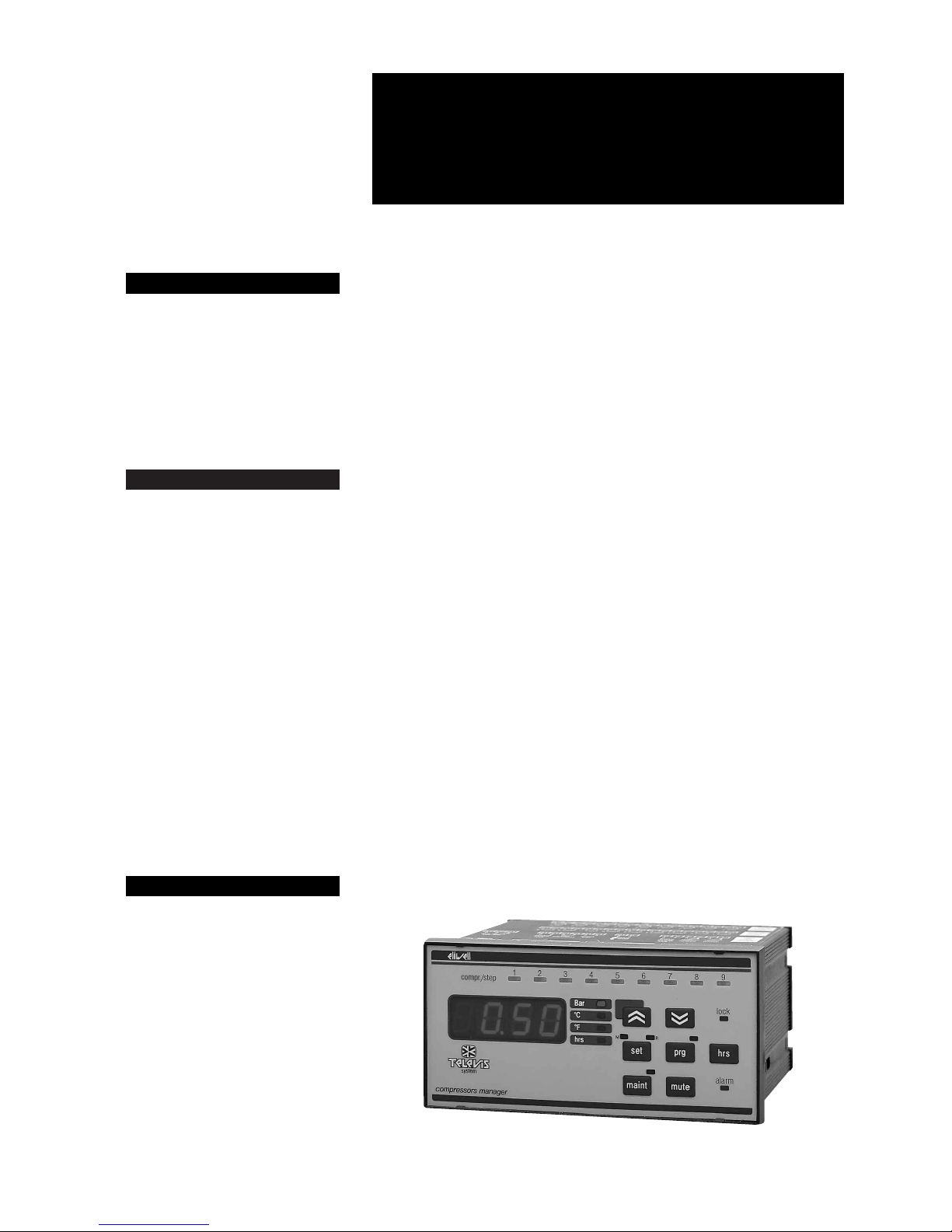
FRONT KEYPAD
“PRG” button: to have access the programming.
“HRS” button: to display/reset the running hours of each compressor.
“MAINT” button: to display/modify the
“available” or “in service” status of each
compressor.
“SET” button: to display/modify the “normal” or the”economy” Setpoints.
“UP” button: to increase the figures.
“DOWN” button: to decrease the figures.
“MUTE” button: to silence/reset an
alarm.
“LOCK led”: to dispaly the keyboard lock
function.
“ALARM” led: to display an alarm condition.
“COMPRESSOR & STAGES” leds: red
and green leds to display the output compressor status.
4 DIGIT DISPLAY: it shows the input
probe value, the default unit of measurement can be programmed with “dEU” parameter. As soon as an alarm occurs the
display will switch back and forth between
the probe read-out and the alarm code label.
INPUT AND OUTPUT
Alarm relay output: remote alarm, the
terminals 1 and 2 are closed when there is
an active alarm.
Safety relay output: the terminals 3 and
4 are open when an EWCM failure appears.
Pressurestat alarm input: high and low
pressurestat input alarms (terminals 5 and
6, “SEP” parameter).
Power supply: input terminals 9 and 10.
Economy set switch: to activate the
HOW IT IS MADE
• Housing: black ABS plastic,
72x144 mm, depth 120 mm
• Connections: quick-disconnect
screw terminal block
• Type of refrigerant: ammonia
• Suction sensor input: NTC or
4…20 mA pressure transducer
(scaleable)
• One pressurestat alarm input
• Global alarm output: relay 6(3)A
250V AC
• Controller breakdown output: relay 6(3)A 250V AC
• Configurable outputs: 9 relays
outputs 6(3)A 250V AC
• Alarm inputs: 9 optoisolated inputs (the same voltage of the supply)
• Serial connection: RS-485 port for
connection to the Televis system
• Consumption: 6 VA
• Power supply: 12, 24, 110, 220 Vac
±10%, 50/60 Hz
WHAT IT IS
The EWCM 809/NH3/S is a controller designed specifically for the
control of a machine room in a refrigeration system.
EWCM 809/NH3/S provides control
management of the compressors
(single units, multistage systems or
compressors having different power).
EWCM 809/NH3/S
rel. 5/98 ing
compressors manager, model for ammonia
PLUS PRODUCT
• Alarm circuit combined with each
compressor
• Clock to set the various operation
setpoints in various time periods
• UL approval pending
Page 2

2EWCM 809/NH3/S 5/98 ing
economy setpoint (terminals 13 and 14
have free voltage contacts, “rSIP” parameter).
Suction probe: input terminals 15 and 16.
Televis System: RS 485, input terminals
19, 20 and 21.
Compressor alarms inputs: when active, the compressor output is swiched off
(terminals from 22 to 39, “ALIP” parameter).
Compressor relay outputs: to supply
the contactors of the compressors (terminals from 44 to 61).
PARAMETER PROGRAMMING
ENTERING THE PROGRAMMING
MODE
The EWCM is provided with two levels of
parameters programming: operating “oPr”
and Configuration “CnF”.
To have access the “oPr” menu, push and
release the “prg” button and then the “UP”
arrow.
To have access the “CnF” menu, push the
“prg” button twice and then the “UP” arrow.
If a password has been activated, the
“PAS” label will be showed before entering
the programming.
To exit the programming mode, push the
“prg” button another time, all the changes
will be automatically memorized.
HOW TO DISPLAY AND MODIFY
THE PARAMETERS
After entering programming, to display a
parameter label push the “UP” or “DOWN”
arrows:
- to show a parameter value push the “set”
button;
- to modify the parameter value push the
“UP” or “DOWN” arrows;
- to exit the parameter value push the ”set”
button.
PASSWORDS
The passwords “Psc” and “Pso” are provided to enter the Configuration and
Operating parameters programming.
To activate the password enter the programming mode, select the password label and set the password number.
CONFIGURATION PARAMETERS
System capacity
CPnU: ComPressor nUmber.
Number of compressors installed.
CtyP: Compressor tyPe.
0 = compressors having different power
(Neutral Zone Control);
1 = compressors having the same power
(Proportional Control).
Note: compressors having the same power, but without partial reduction valves.
- Neutral Zone (dead band) is used with
compressors having a big power.
- Proportional control is used with small
power compressors.
CPSt: ComPressor Step.
Number of steps of each compressor (only
Parameter Description Range Default Unit
CONFIGURATION PARAMETERS
CPnU ComPressor nUmber 1…11 7 number
Ctyp Compressor tyPe 0 / 1 1 number
CPSt ComPressor Step 1…6 1 number
PC1…PC11 Power Compressor 1…11 1…255 1 number
FtyP Freon tyPe / / /
PA04* Pressure At 0…4 mA 0…8 0,5 Bar
PA20* Pressure At 0…20 mA 0…31 8 Bar
CAL** CALibration –0.5…0.5 0 Bar
CAL*** CALibration –5…5 0 °C
SEP SEt (alarm) Polarity 0 / 1 1 number
rSIP reduced Set Input Polarity 0 / 1 1 number
ALIP ALarm Input Polarity 0 / 1 1 number
StPP Step outPuts Polarity 0 / 1 1 number
Psc Password configuration 0…255 0 number
tAb tAble of parameters / / /
OPERATING PARAMETERS
Pri Primes 0…59 0 minutes
HoUr HoUrs 0…23 0 hours
daY dAY 1…7 0 number
dEU dEfault Unit 0 / 1 / 2 0 number
Pbd Proportional band 0.1…5 0,4 Bar / °C / °F
onon on/on (compressor) 0…255 5 minutes
oFon oFF/on (compressor) 0…255 5 minutes
don delay on 0…5000 15 seconds
doF delay oFF 0…255 5 seconds
donF delay on/oFF 0…255 15 seconds
FdLy First deLay on 0 / 1 1 number
FdLF First deLay oFF 0 / 1 1 number
odo output delay at on 0…255 0 seconds
LSE Lower SEt 0.1 / HSE 0.2 Bar / °C / °F
HSE Higher SEt LSE / 25 5 Bar / °C / °F
StrS Start time reduced Set 0…24 0 hours
SPrS Stop (time) reduced Set 0…24 0 hours
rSd1…rSd7 reduced Set day 1…7 0 / 1 0 number
UAro Unit Alarm override 0 / 1 1 number
Aro Alarm override 0…255 15 minutes
PAO Power Alarm Override 0…255 30 minutes
LAL Lower ALarm 0.01…25 5 Bar
HAL Higher ALarm 0.01…25 5 Bar
tAo time Alarm override 0 255 minutes
SEr SErvice 1…9999 3000 hours
PEn Pressurestat Errors number 0…15 5 number
PEI Pressurestat Errors Interval (time) 0…15 15 minutes
CPP Compressor Probe Protection 0 / 1 0 number
SPr Step Probe protection 0 / CPnU 1 number
PoPr Power (with faulty) probe 0 / n 0 number
rELP rELative Pressure 0 / 1 1 number
Loc keyboard Lock function 0 / 1 1 number
Pso Password operating 0…255 0 number
FAA FAmily Address 13…14 13 number
dEA dEvice Address 0…14 0 number
DEFAULT SETTINGS - STANDARD MODELS
Page 3

3 EWCM 809/NH3/S 5/98 ing
for CtyP = 1).
If CtyP = 0, this parameter will default to 1.
PC1…PC9: Power Compressor 1…9.
These parameters set the power of each
compressor from1 to 255 (only for CtyP =
0).
For instance: 3 compressors of 10, 20 and
40 Hp; “PC1” = 10, “PC2” = 20 and “PC3 ”
= 40, or “PC1” = 1, “PC2” = 2 and “PC3”
= 4.
FtyP: Freon tyPe.
Not available.
Suction line sensor configuration
*not available for NTC models.
PA04*: Pressure At 0…4 mA.
Read-out corresponding to the low input
signal of 4 mA.
PA20*: Pressure At 0…20 mA.
Read-out corresponding to the high input
signal of 20 mA.
CAL: CALibration.
Read-out probe calibration.
Other inputs configuration
SEP: SEt (alarm) Polarity.
Pressurestat input polarity (terminals 5 and
6). It selects the active condition for a pressurestat alarm.
0 = active alarm without voltage;
1 = active alarm with voltage.
rSIP: reduced Set Input Polarity.
Economy set input polarity (terminals 13
and 14). It selects the active condition for
an active economy set.
0 = active economy set with open contact;
1 = active economy set with closed contact.
ALIP: ALarm Input Polarity.
Alarm input polarity (terminals 22 to 39). It
selects the active condition for an input
compressor alarm.
0 = active alarm without voltage;
1 = active alarm with voltage.
StPP: Step outPuts Polarity.
It selects the active output of the partial reduction valves (only for compressor having
the same power).
0 = it means active step without voltage;
1 = it means active step with voltage.
Password
Psc: Password configuration.
Password to have access to the programming Configuration parameters.
tAb: tAble of parameters.
It cannot be modified.
OPERATING PARAMETER
Economy set clock setting
Pri: Primes.
Minute setting.
HoUr: HoUrs.
Hours setting.
dAY: daY.
Day setting.
NOTE: 1 = Sunday; 7 = Saturday.
Control cycle setting
dEU: dEfault Unit.
Default unit of measurement.
0 = bar;
1 = °C;
2 = °F.
Pbd: Proportional band.
Proportional band width, the unit of measurement is expressed by “dEU” parameter. With compressors having the same
power, the Proportional band width is divided by the number of the available resources to give the pressure step width for
each resource. With compressors having
different power, “Pbd” sets the dead band
witdh: if the probe value is higher than the
setpoint + Pb/2, the compressors will be
swiched on by following the delay time parameters setting. If the probe value is lower than the setpoint – Pb/2, the
compressors will be switched off by following the delay time parameters setting. If the
probe value is within the proportional band
no compressor will be swiched on or off.
onon: on/on (compressor).
Compressor on/on delay. Time delay in
minutes, between two consecutive starts
of the same compressor.
oFon: oFF/on (compressor).
Compressor off/on delay. Time delay between stop and start of the same compressor.
don: delay on.
Step delay on. Time delay in seconds, between starts of two steps.
doF: delay oFF.
Step delay off. Time delay in seconds, between stops of two steps.
donF: delay on/oFF.
Step delay on/off. Minimum resource activation time, in seconds.
The activated compressor will work minimum for the time set in this parameter.
FdLy: First delLay on.
The delay time “don” can be used also before the first request of power.
0 = no;
1 = yes.
FdLF: First deLay oFF.
The delay time “dof” can be used also before the first request of power.
0 = no;
1 = yes.
odo: output delay at on.
After swiching on the power supply the
output will be off during the time set in this
parameter.
Setpoint
LSE: Lower SEt.
Lower setpoint limit for both setpoints, the
default unit of measurement is expressed
by “dEU” parameter.
HSE: Higher SEt.
Higher setpoint limit for both setpoints, the
default unit of measurement is expressed
by “dEU” parameter.
StrS: Start time reduced Set.
Start time for economy set.
SPrS: StoP (time) reduced Set.
Stop time for economy set.
rSd1…rSd7: reduced Set day 1…7.
Day of the week to activate the economy
set.
0 = no;
1 = yes.
NOTE: rSd1 = Sunday; rSd7 = Saturday.
Alarms
UAro: Unit Alarm override.
Unit of measurment for alarm silencing
(“Aro”).
0 = minutes;
1 = hours.
Aro: Alarm override.
Alarm silencing override time.
PAO : Power Alarm Override.
Power on pressure alarms override time, in
minutes. After turning on the power supply,
the pressure alarms are silenced during
this time.
LAL: Lower Alarm.
Low pressure alarm limit. If the probe signal is lower than Set – LAL, the “Er03” low
alarm label is displayed.
HAL: Higher Alarm.
High pressure alarm limit. If the probe signal is higher than Set + HAL, the “Er04”
high alarm label is displayed.
tAo: time Alarm override.
Time delay before displaying the
“Er03/Er04” alarm condition, in seconds.
SEr: SErvice.
Numer of compressor running hours.
When a compressor running hours reache
the number set in this parameter, the
“Er14” maintenance warning message will
be displayed.
PEn: Pressurestat Errors number.
Number of high and low pressurestat errors on terminals 5 and 6.
PEI: Pressurestat Errors Interval (time).
CPP: Compressor Probe Protection.
It selcts the system protection when the
probe is faulty “Er01”.
0 = the system operates with the same
compressors which were working when
the probe failed;
1 = the system operates with the number
of stages set in “SPr” in case of compressors having the same power; or with the
power level set in “PoPr” in case of compressor having different power.
SPr: Step Probe protection.
Number of stages to run the system if the
probe is faulty (CtyP = 1 and CPP = 1).
Parameter Description Range Default Unit
tAb tAble of parameters / / /
EL 1 ELIWELL 1 / / /
EL 2 ELIWELL 2 / / /
* Not available for NTC models.
** For programmable input 4…20 mA.
*** For input probe NTC.
Page 4

4EWCM 809/NH3/S 5/98 ing
PoPr: Power (with faulty) Probe.
Power level to run the system if the probe
is faulty (CtyP = 0 and CPP = 1).
User interface
rELP: rELative Pressure.
Relative or absolute pressure read-out.
0 = absolute;
1 = relative.
Loc: keyboard Lock function.
It disables the following functions: setpoint
adjustment, compressor running hours reset, avilable and in service compressor
status control. The “Loc” parameter can
however be modified.
0 = keyboard unlocked;
1 = keyboard locked.
Pso: Password operating.
Password to access the programming
Operating parameters.
Tele-assistance
FAA: FAmily Address.
It selects the family number when connected to a Televis network.
dEA: dEvice Address.
It selects the device number when connected to a Televis network.
tAb: tAble of parameters.
This parameter can not be modified.
EL1: ELIWELL 1.
This parameter can not be modified.
EL2: ELIWELL 2.
This parameter can not be modified.
USER INFORMATIONS
How to display/modify the setpoint
The EWCM is provided with two setpoints:
normal and economy (used during the
night time or holidays).
Push and release the “set” key to display
the normal set, the other unit of measurement and the economy set can be displayed by pushing repeatedly the “set” key
whithin 5 seconds.
The corresponding led status lights on the
right side of the display shows the unit of
measurement selected, the active setpoint
displayed is identified by the “N” or “R”
green led, the other setpoint by the “N” or
“R” blinking light. By pushing “UP” or
“DOWN” arrow keys the selected setpoint
can be modified.
Compressors leds status
Before switching on an output the corresponding green led blinks, this blinking period depends on the delay parameters.
When the relay output has been swiched
on the corresponding red led will light.
Note: after turning on the power supply the
pressure may result out of range, therefore
to start up the system the EWCM controls
the compressors simply as the probe value were higher than the alarm limits.
After the time delay set to the parameter
“PAO”, if the probe value is still out of
range, the EWCM will start working following the “CPP”, “SPPr” and “PoPr” parameters setting.
How to display/reset the compressors
running hours
Push and release the “hrs” key to display
the first compressor running hours, the
“hrs” led will light; push the “UP” arrow
within 5 seconds to display the successive
compressors, the corresponding red led
will blink; the compressor running hours
can be reset by keeping pressed the
“mute” key for 5 five seconds; to exit this
procedure push and release the “hrs” key
once again.
How to display/modify the “MAINTENANCE” and “IN SERVICE” status
Push and release the “maint” key to display the first compressor status, the corresponding red led blinks and the “maint”
green led is on.
The “onLn” (on line) message means that
the output is “in service”.
To modify it keep the “mute” key pressed
for 5 seconds, the “oFLn” message means
that the output is in “maintenance” and the
corresponding red led will blink.
During the working cycle the “maintence”
status of a compressor is shown by the
blinking of the corresponding red and
green leds, in this case the output compressor is always swiched off.
Digital alarm inputs
High and low pressurestat alarm
Terminal 5 and 6, “SEP” parameter.
Until the condition alarm on these terminals is active, the EWCM keeps all the
compressor outputs switched off. This
kind of alarm does not need a manual reset.
If during the “PEI” interval time the number
of pressurestat errors reaches the “PEn”
value, the “Er0L” or the “Er0H” warning
message will be displayed. “Er0L” means
low pressurestat alarm and “Er0H” means
high pressurestat alarm. Press the “mute”
button for 5 seconds to reset this alarm.
This function can be excluded by setting
PEn = 0.
Alarm inputs linked to outputs
Terminals from 22 to 39, “ALIP” parameter.
Each compressor alarm protection must
be connected to the corresponding alarm
input (e.g. low compressor oil level, klixon
etc.). If one of these alarms is active, the
corresponding compressor output will be
switched off, the corresponding red led will
blink, the “alarm” red led will light and the
display will show the “Er02” warning message.
This alarm does not need a manual reset.
Alarm silencing
When an alarm condition is active, the
alarm relay will be energized and the terminal 1 and 2 are closed.
To silence an alarm push and release the
“mute” key, the alarm relay will be de-energized and the “alarm” led will blink if the
alarm condition is still active. The silencing
time depends on the “UAro” and “Aro” parameters setting.
If during the silencing time another alarm
becomes active, the silencing time will be
reset, and the new alarm condition will be
displayed.
Alarms that need a manual reset: keep
pressed the “mute” key, the display will
show the “CAnC” message and then the
“rES” message.
ALARM WARNING MESSAGES
Er0L…Er0H: Error Low…High.
Low and high pressurestat alarms. It
switches off all the compressor outputs.
Er01: Error 01.
Faulty probe alarm, see “CPP”, “SPr” and
“PoPr” parameters setting.
Er02: Error 02.
Inputs linked to outputs compressor
alarms. It switches off the corresponding
compressor output.
Er03: Error 03.
Low pressure alarm. It appears when the
probe value is lower than the Set – LAL.
Er04: Error 04.
High pressure alarm. It appears when the
probe value is higher than the Set + HAL.
Er11: Error 11.
Wrong clock programming. Check “Pri”,
“HoUr” and “dAY” parameters setting.
Er12: Error 12.
Wrong parameter programming. More
than the 9 available outputs have been
programmed. It needs a manual reset.
Er13: Error 13.
Wrong data memory. It needs a manual reset.
Er14: Error 14.
Maintenance alarm.
TECHNICAL DATA
Housing: black ABS plastic, 72x144 mm,
depth 120 mm.
Mounting: flush panel mount
(67x136 mm) with brackets.
Connections: quick-disconnect screw
terminal block.
Data storage: non-volatile EEPROM
memory.
Type of refrigerant: ammonia.
Suction sensor input: NTC or 4…20 mA
(scaleable).
Pressure switch input: one (1).
Global alarm output: relay 6(3)A 250V
AC.
Controller breakdown output: relay
6(3)A 250V AC.
Configurable outputs: 9 relays outputs
6(3)A 250V AC.
Alarm inputs: 9 inputs (250 Vac optoisolated; other voltages on request).
Serial connection: RS-485 port for connection to the TELEVIS system.
Consumption: 6 VA.
Power supply: 12, 24, 110, 220 Vac
±10%, 50/60 Hz.
Page 5

5 EWCM 809/NH3/S 5/98 ing
22 23 24 25 26 27 28 29 30 31 32 33 34 35 36 37 38 39
t2 t3 C2 t2 t3C1
K1 K2 K3 K4 K5 K6 K7 K8 K9
44 45 46 47 48 49 50 51 52 53 54 55 56 57 58 59 60 61
K1 K2 K3 K4 K5 K6 K7 K8 K9
EWCM 809 NH3 terminals 44 - 61
P
N
EWCM 809 NH3 terminals 22 - 39
alarm
inputs
1 2 3 4 5 6
EWCM 809 NH3 terminals 1 - 21
10
13 14 15 16 19 20 21
POWER SUPPLY
low
pressure
alarm input
reduced
set
alarm
relay
gnd
–
+
NTC
evap. probe
TELEVIS
system
connection
(optional)
safety
relay
C
3
t2 t3
9
out 1 out 2 out 3 out 4 out 5 out 6 out 7 out 8 out 9
relay outputs
THREE COMPRESSORS HAVING THE SAME POWER AND TWO PARTIAL REDUCTION VALVES
 Loading...