

Page 1
RGF 300
Three-phase voltage regulator
Page 2
WARNING !
HIGH LEAKAGE CURRENT: first connect to earth !
The rgf300 is a voltage regulator for three phase motors which operates
connected to the three phase mains voltage. The regulator must be installed by
qualified personnel who will connect the electric supply, attach the cables in
their permanent positions and commission the plant.
Incorrect installation of the rgf300 voltage regulator or the fan connected to it
may cause damage to objects or people so ensure the instructions in this manual
and all required security measures are read and followed carefully.
When receiving the goods, check that the packing is intact; in the event of any damage
•
due to transportation, notify the forwarding agent according to legal requirements.
The rgf series of products shown in this manual has been manufactured to the highest
•
standards.
The manufacturer declines all responsibility for accident, loss or damage caused by the
•
use of these appliances. These must be correctly installed by qualified personnel in
conformity with their destined use and, whenever needed, must undergo correct
maintenance which should be carried out while ensuring the safety of people, domestic
animals and goods.
The purchaser must previously ascertain the suitability of the product for the use it is
•
intended for and assume all consequent risks and responsibility.
The rgf300 is a mains voltage regulator which uses the phase-cut principle completely
•
controlled over the three phases. It has been designed to vary the effective voltage on
three phase asynchronous motors for fans following a control signal (either mA, VDC or
Ohm). The appliance is manufactured for industrial use and therefore meets the EMC
standards that relate to industrial environments.
Using the appliance for purposes other than the ones described above will be considered
•
incorrect. In particular, the appliance may NOT be used to supply machine tools or any
other machines where the motor torque-speed characteristic is not quadratic.
If the equipment is intended for civil, commercial and/or light industrial use,
•
supplementary components and other types of equipment are required which can be
supplied on specific request from the purchaser. In this case, the purchaser must
provide a suitable design of the plant in which the applia nce is to be installed ( compliant
with EN 60555 - 2/3 standards regarding disturbance produced by electrical household
appliances and the like.
We decline all responsibility for any errors in the catalogues, publications or other
•
written documents. The information in this manual is not binding and we reserve the
right to make changes to the products without prior notice, at any time and in an y way
that we deem convenient for production purposes or useful for increasing functionality
and performance.
RGF 300
2/53
Page 3
SAFETY RULES !
This appliance has been designed to give excellent performance provided it is installed and used carefully in
a suitable electric environment by qualified personnel.
The following rules
Follow the instructions in this manual exactly and observe all safety measures in force.
•
Do NOT tamper with or disassemble the regulator's internal components; doing so will
•
INVALIDATE THE GUARANTEE and may cause unnecessary damage.
The regulator does not contain components that can be repaired by the user.
•
•
The regulator must be suitably and effectively earthed by the installer according to the standards in force;
earthing is essential for the EMC filt er to oper ate cor re ctly .
•
The user must be protected from the electric supply and the motor must be protected from possible
overloads in compliance with the standards in force.
DO NOT
•
DO NOT
•
circumstances.
•
Before supplying power to the unit, check carefully that the power and earth are correctly connected.
•
If the mains supply is "disturbed", which may be due to other electrical power components causing
irregularities in the supply (power contactors), it is recommended that supplementary three phase
SURGE ARRESTER
‘
•
Avoid repeatedly connecting and disconnecting the power supply to the regulator; a constant supply
keeps the regulator at working temperature and eliminates problems caused by condensate inside the
protection case.
•
Alternatively, use the remote terminal board contact 'MB' S2 = ON/OFF.
•
The S2 = ON/OFF contact on the MB terminal board does not cut the mains supply and therefore cannot
be used as a safety switch.
•
Install the regulator out of direct sunlight so that the container cannot get overheated and cause a
reduction in the maximum load current.
•
The appliance may operate at environmental temperatures up to 50°C. Do not install it where this
temperature may be exceeded or the integrity of the regulator will be compromised and the appliance
may make the user appliance operate at full load (100%) with all consequent effects.
•
The appliance must be stood vertically to encourage heat dissipation and to ensure there is a sufficient air
circulation and free space measuring
be grouped together on a single electric board, provide forced air circulation with a fan or cooling unit of
sufficient power.
•
Use the holes on the lower and power terminal board sides of the appliance, for entrance of the
connection cables. This will prevent water, dust etc. from getting in and will ensure the
level is maintained using adequately sized cables and sheaths of suitable quality.
Reassemble and check the cover of the external protection panel is properly closed.
•
DO NOT alter or damage the identification stickers on the equipment.
•
DO NOT force the trimmers to rotate beyond their set mechanical travel.
•
Only alter the trimmers intended for regulation.
•
Under no circumstances alter the trimmers marked with the spot of red paint.
•
must be obeyed
supply the regulator without the internal protection panel made from lexan.
touch the electrical parts of the circuit when the power supply is connected under any
’
filters are installed direc tly on the regulat or supp ly.
when installing the regulator :
150 mm
above and below the regulator. If several regulators are to
IP55
protection
WARNING !
HIGH LEAKAGE CURRENT: first connect to earth !
RGF 300
3/53
Page 4

1.0 P
RESENTATION
1.1 D
1.2 I
1.3 P
1.4 E
1.5
2.0 E
LECTRICAL CONNECTIONS
2.1 E
2.2 E
2.3 E
3.0 C
OMMISSIONING PROCEDURE
3.1 J
3.2 M
3.3 M
3.4 S
3.5 S
3.6 M
3.7 O
4.0 C
ONTROL TRIMMER
4.1 M
4.2 M
4.3 C
4.4 P
4.5 S
4.6 S
4.7 M
5.0 HELP
6.0
RGF
300
7.0
8.0 L
9.0 D
TROUBLESHOOTING
IABILITY AND RESIDUAL RISKS
ISCLAIMER
CONTENTS
……………………………………………………..….……………………………
ESCRIPTION
NSTALLATION AND MACHANICAL DIMENSIONS
RINCIPLE OF OP ERATION
1.3.1 O
1.3.2 A
LECTRIC MOTORS
1.4.1 M
RGF
300
LECTRICAL CONNECTIONS, POWER CARD
LECTRICAL CONNECTIONS, ANALOGUE INPUT SIGNALS
2.2.1 C
2.2.2 C
2.2.3 C
2.2.4 R
2.2.5 C
LECTRICAL CONNECTIONS
2.3.1 O
UMPERS
ASTER, VERSION
ASTER, VERSION
LAVE, VERSION
LAVE, VERSION
ASTER, VERSION X OR
PTIONAL MODULE FOR DOUBLE SET-POINT CONFIGURATION
AX
. O
IN
. O
UT-OFF REGULATION
ROPORTIONAL BAND REGULATION
4.4.1 V
4.4.2 V
ET-POINT RE GULATION (MODELS
4.5.1 D
OFT-START REGULATION
ANUAL REGULATION (HEAT-PUMP
I
ORTABLE DISPLAY UNIT
– P
EASY REFERENCE COMMISSIONING GUIDE
……………………………….……………………………………………………………
………………………………………………………………………………..
……………………………………………..
……………………………………………………………………
PERATING MODE
PPLICATION
…………………………………………………………………
……………………………………………………………………….
…………………………………………………………………………..
AGNETOTHERMAL PROTECTION
TECHNICAL DATA
….……………………………………………………………….
……..……………………………………………
…………………………………………………………………………
……..…………………………………………….
……...……………………………..
ONNECTION OF
ONNECTION OF
ONNECTION OF OTHER SENSORS AND CONTROL SIGNALS
EMOTE CONNECTION FOE A CURRENT (M
ONNECTION OF THE RGF
PERATING SELECTION
PRESSURE TRANSDUCERS
XSK
TEMPERATURE SENSORS
NTC
……………………………………
…………………………………….
………………………….
OR VOLTAGE (VDC) CONTROL SIGNAL
A)
MULTIDRIVER
FF INPUTS / OUTPUT
, ON-O
INPUTS / OUTPUT
………………………
………………………………………
………………………………………………………………
…………….…………………………………………………………
……………………………………………………………………………………..
M (4-20mA),
V (0-10VDC),
M (0-20mA),
V (0-10VDC),
Y (NTC °C),
FOR 1 OR 2 CONTROL
FOR 1 OR 2 CONTROL
FOR 1 OR 2 CONTROL
FOR 1 OR 2 CONTROL
FOR 1 OR 2 CONTROL
INPUTS ……………………………
INPUTS ……………………………
INPUTS ………………..………..….
INPUTS ……………………………..
INPUTS …………….………..
(SP1-SP2) …………….…...
…………………………………………………………………………………
UTPUT REGULATION
UTPUT R
………………………………..… T
………………….. T
………………..……..…. T
……..……... T
ERSIONS WITH
ERSIONS WITH
MASTER
SLAVE
REGULATOR OPERATION
REGULATOR OPERATION
M, V, X, Y) … T
ECADIC SET-POINT OPTION (MOD
………………...……. T
) ..………... T
. M, V, X, Y) P3 ………………………………..
RIMMER
RIMMER
RIMMER
RIMMER
RIMMER
RIMMER
RIMMER
P4 …………………………….
P5 ……………………………
P6 ……………………………
P2 ……………………………
………………………………
……………………………….
P3 …………………………..
P1 ….……………………….
P7 …………………………..
…………………………………………………………………
………………………………………………..
. . . ………………………………….…………………………………………....
……………………………….………………………………………
.
RGF 300
4/53
Page 5

1.0 P
HANK YOU
T
RESENTATION
for choosing an
rgf300
series three phase voltage regulator, designed specifically to give the
maximum yield and greatest ease of use.
Like all our products, it has been built to the very highest quality standards using electronic components of
the utmost reliability which have undergone functional tests that guarantee use of the product for at least
30,000 hours
rgf300
The
of continuous operation without problem.
regulator is a power unit designed to meet requirements of quality and flexibility of use in plants
and machines in which proportional variation of the speed of rotation of the fans is essential.
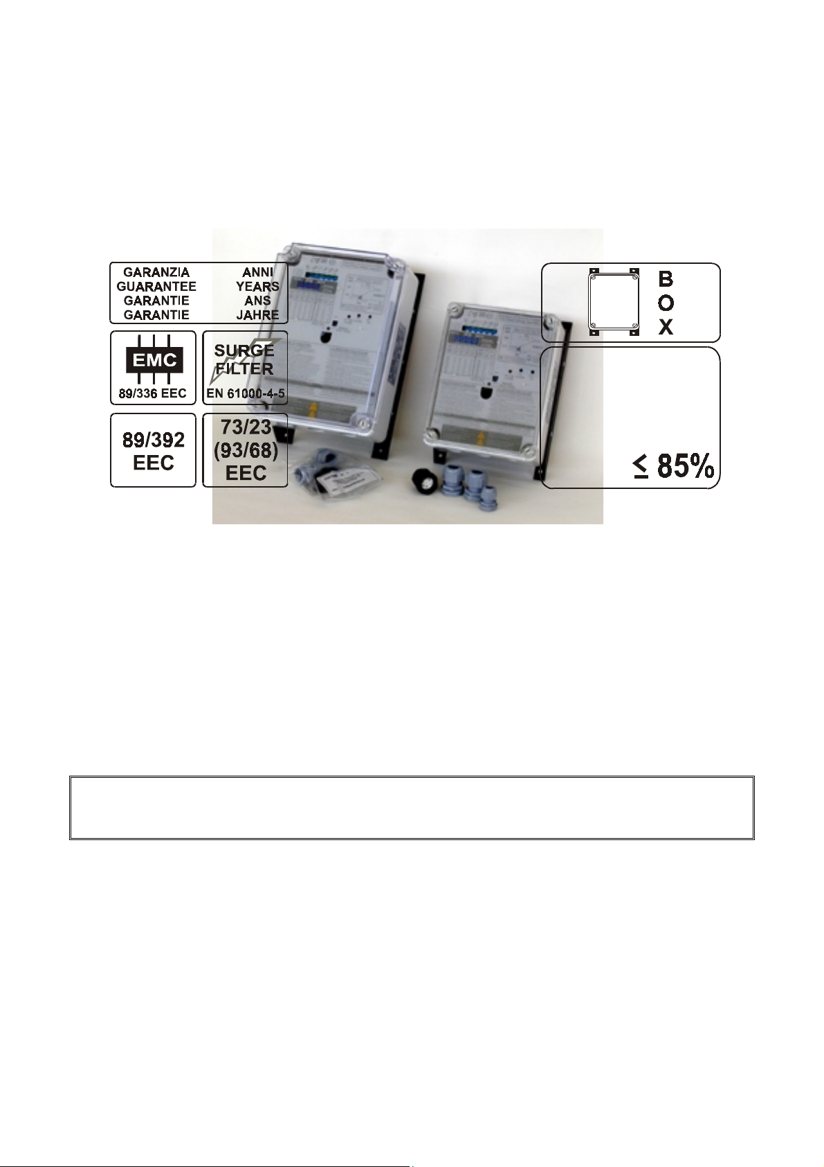
The regulator is housed in a
during ordinary use (
120°C
GEWISS GW Plast
), increased mechanical impact resistance (
120°C
case (
fig. 1
) which guarantees high heat resistance
IK = 08
) and a protection level (
IP55
that allows the regulator to be installed out of doors.
Inside the case there is a lexan protection panel displaying instructions for use and commissioning of the
rgf300
The
.
12A rgf300
Vdc
mA
NTC
is shown in
fig. 1.
fig. 1
Before installing the device, you are invited to read this manual which describes the necessary
procedures for correct installation and commissioning of the machine.
)
rgf300
RGF 300
5/53
Page 6
Like all our products, the
subsequent modification
Since all these products are not used as "
machines, the standards' compatibility test was carried out under typical operating conditions.
The essential requirements of the directive are satisfied by conformity to "
industry.
rgf300
EEC/92/31
series bears CE marking as required by directive
on electromagnetic compatibility.
stand alone
" appliances but incorporated into other plants or
generic standards
3
89/336/ECC
IP 55
120°C
STOCK & WORK
- 20
°C
+85
°C
UR%
and its
" for heavy
- 20
+50
EN 50081-2
EN 55011
EN 55011
ENV 50140 (IEC 801-3)
ENV 50141
IEC 801-4
IEC 801-2
The tests and checks for conformity have been carried out according to the procedures described in the
product's technical documentation. The system used was formed by an
cable and relative controls, a power supply cable, a motor cable and a fan.
Responsibility for the f inal characteri stics of the syste m or plant rega rd ing th e EMC directiv e
rests with the installer. The equipment must be install ed in observance of the regulation s in
force using the information presented in this manual.
emission standard,
EN 50082-2
class B, for radiated disturbances
class A, for conducted disturbances
for susceptibility (on the power supply)
for conducted susceptibility on power lines
for fast transistors (bursts / high frequency disturbances)
for electrostatic discharge (
immunity standard, and in particular:
ESD
)
rgf300
fig. 2
voltage r egulator , a contr ol
RGF 300
6/53
Page 7
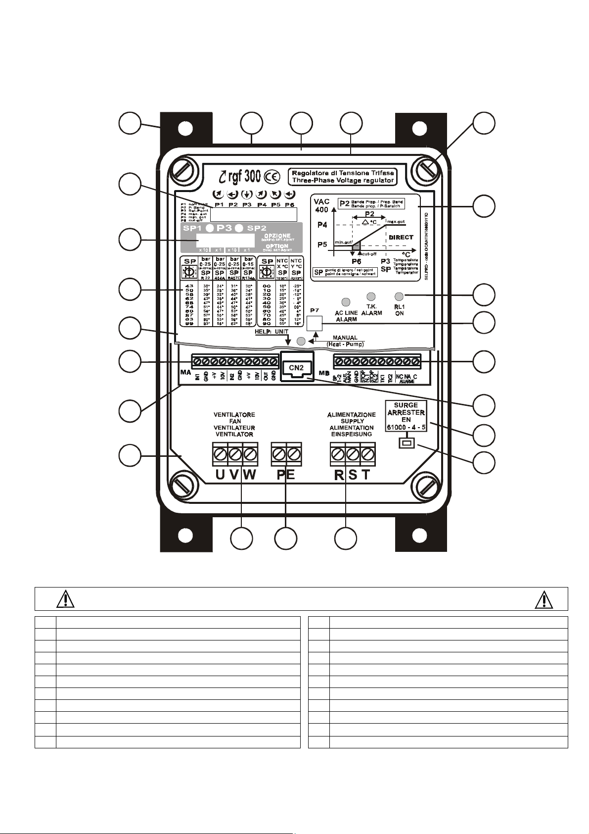
Fig. 3
represent the
22
1
2
3
4
5
6
7
rgf300
regulator with the general contents
21
20
19
8
9
10
fig. 3
18
17
16
15
14
13
12
11
CONTENTS of rgf300 regulator
Control Trimmer for work parameters regulation
1.
Reference table for Set-point rotary centesimal switch
3.
Terminal block for analog inputs/output signals
5.
Power card (lower)
7.
Terminal block for PE connection
9.
SURGE ARRESTER circuit / PE faston connection
11.
I
CN2 connector for HELP
13.
Control Trimmer for Manual mode (heat-pump) regulation
15.
Characteristic with function parameters
17.
Macrolon cover of the case
19.
Black anodized heat sink
21.
display unit
Double 10 positions rotary switch for Set-point (optional)
2.
Lexan internal panel for protection against direct contact
4.
Control card (upper)
6.
Terminal block for load connection (U-V-W)
8.
Terminal block for threephase power supply (R-S-T)
10.
SURGE ARRESTER
12.
Terminal block ON-OFF auxilary inputs/output sig nals
14.
Status LED
16.
Cover screws
18.
20.
GEWISS GW Plast 120°C case
Screws hole for wall installation
22.
circuit like EN 61000-4-5
RGF 300
7/53
Page 8
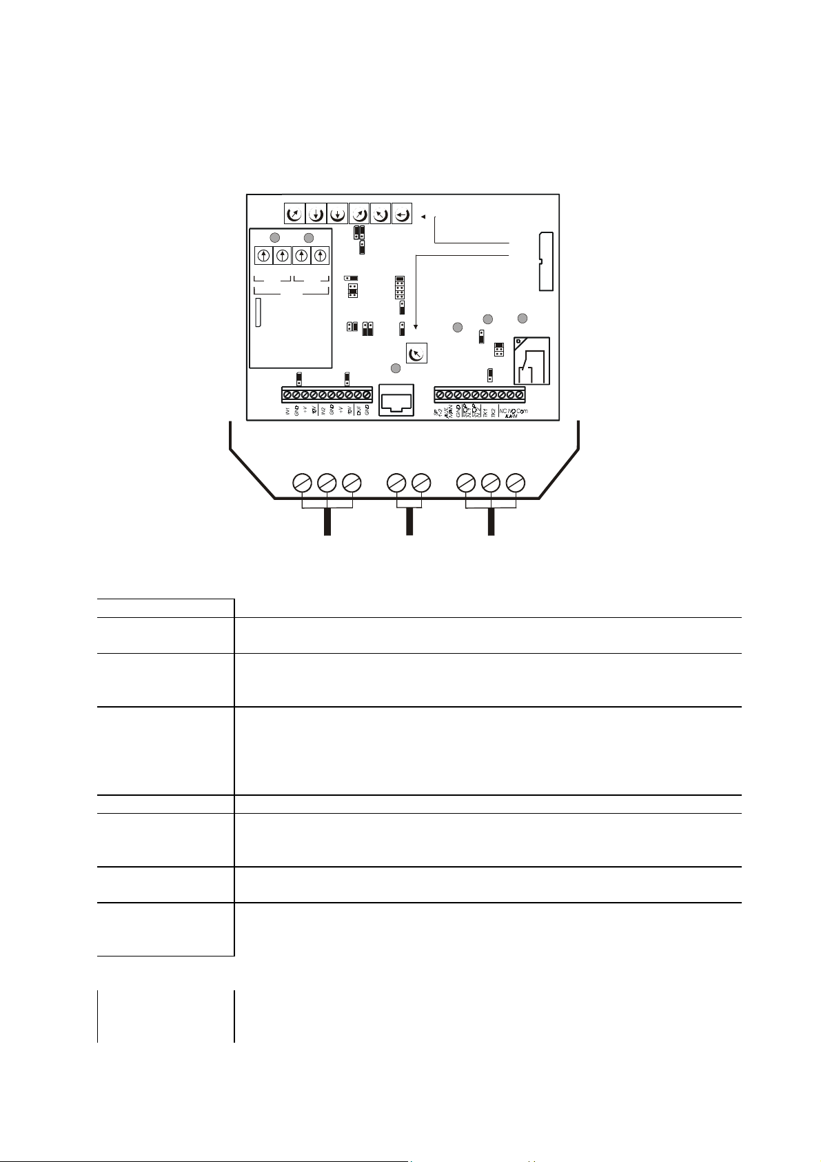
1.1 DESCRIPTION
rgf300
The
mounted inside the
The two cards represent the
series three-phase cutting regulators comprises two electronic cards on a vetronite support
GEWISS IP55 GW Plast
control
SP1
0
9
1
2
8
3
7
4
6
5
SW1 SW2 SW3 SW4
SP1
CN3
RGFPB10640
(OPTIONAL)
MA
control card
The
•
trimmers
!"
centesimal switch
•
relay
•
Leds
AC LINE ALARM
T.K. ALARM
RL1 ON
MANUAL
•
jumpers
•
flat cable
CN2
•
•
Inputs/output
signals terminal
boards
power card
The
•
power supply
terminal boards
contains the following regulation, connection and signalling components:
Marked "Pn"; used to set working parameters
Marked “SW”; used for the
on the transducer skale (only with
Marked "
Relay with commutation contact for external signalling of correct operation or
stop (see selection jumper
Marked "
RED Led DL1
RED Led DL2
GREEN Led DL3
YELLOW Led DL4
Marked
Marked
The flat allows connection to the control and power cards.
Check the flat is securely fixed during maintenance or commissioning.
Rapid connector to the portable
parameters
Terminal board MA
Terminal board MB
contains the following connection components:
'M1'
for three-phase input supply
'M2'
for three-phase output
‘M3’
120°C
section (upper) and
case.
power
section (lower).
P1
Mm MmMm
0
9
9
1
2
8
8
3
7
7
4
6
6
5
P3
J16
0
5
1
4
SP2
1
2
P2
2
3
7
P4
SP2
0
9
8
6
5
P3
1
J1
2
1
2
3
4
1 2
1
2
3
J8 J10
J9
1
J17
2
P6
P5
P1
1
2
3
4
5
1
2
1
2
P7
Mm
= soft-start
P2 Proportional Band
=
P3 Set-Point
=
P4
= max. output
P5
= min. output
P6
= cut-off
P7
= Set- H.P. mode
ALARM
ALARM
T.K .
AC LINE
1
J13
2
J15
MmMm
Mm
1
J2
2
1
J3
2
J4
J6
J5
J5
J7
1
J12
2
J11
MANUAL
CN 2
M2 M3 M1
fig. 4
simply
RL1"
J14
Dln"
to signal "regulator stop/fault"
to signal "external heat protection (
to signal commutation relay
to signal
'Jn'
; used to change preset operational modes
'FL'
for connection of the control analogue input signals
for connection of the ON-OFF inputs and outputs
U, V, W
for the
Earth / PE
connection
Set-Point parameter, with
PB 1064
).
HEAT PUMP
“
R,S,T
I
HELP
FL
RL1
ON
RL1
J14
1
2
3
1
2
MB
option)
T.K
)."
RL1
”
mode
10
unit for display of the
in the
N.O.
100
working po int s
position
rgf300
's wor k
RGF 300
8/53
Page 9
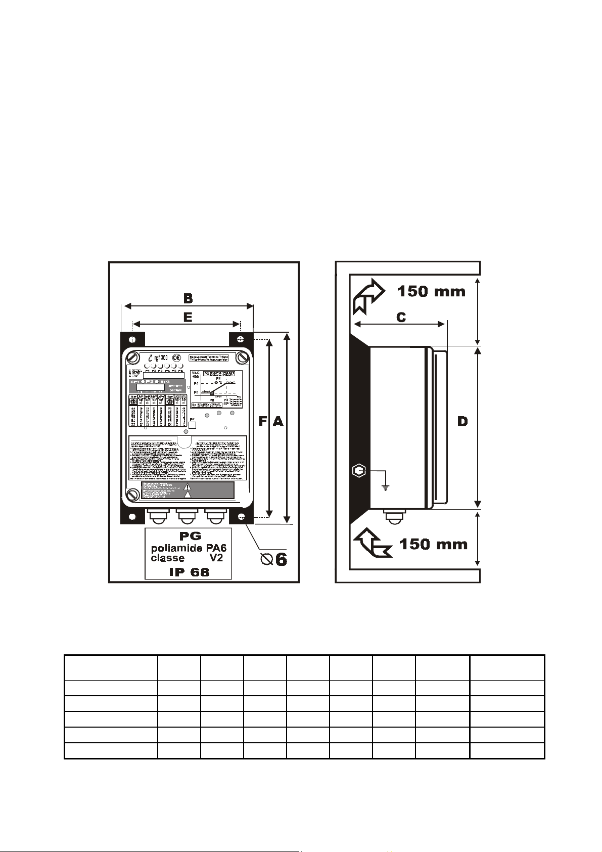
1.2 INSTALLATION AND MECHANICAL DIMENSIONS
rgf300
The
the side fins before connecting to the power supply.
The holes provided on the lower part of the regulator are for entry of the electric connection cables:
•
four pole line (
•
four pole line (
•
signal cable lines for the analogue inputs and digital outputs.
To make installation simpler, all regulators are also fitted with stuffing boxes in
IP68
The regulator is cooled by natural convection and so air must be able to pass freely below and above the
appliance.
Therefore ensure there is at least
regulator must always be securely assembled and fixed using the four (4) attachment screws on
three phase + Earth
three phase + Earth
) to power the regulator,
) to power the load,
PA6
polyamide, class V2,
, for use with the power and signal cables.
150 mm.
of free space above and below the regulator.
AC LINE
HELPi U NIT Heat - Pu mp
ALARM
ALARM
RL1ONT.K.
fig. 5
Mechanical Dimensions
MODELS A B C D E F kg.
rgf 312
rgf 320
rgf 325
rgf 340
rgf 360
286 201 130 255 181 255 4.0
351 237 181 317 185 320 5.5
351 237 201 317 172 320 8.0
416 318 178 397 275 385 11.0
460 318 228 397 260 410 17.0
Fixing
∅∅∅∅
screw holes
∅ 6
∅ 6
∅ 6
∅ 6
∅ 8
RGF 300
9/53
Page 10

Table 1
RGF 300
10/53
Page 11

1.3 PRINCIPLE OF OPERATION
rgf300
The
series appliances are voltage regulators that use the phase cutting principle totally controlled over
three phases.
The regulators, also referred to as speed controls, have been designed to change the average voltage on the
following types of equipment, according to a control signal:
•
asynchronous three phase motors connected to
•
electrical resistor device s with sec tio ned
fans, pumps, agitators, mixers
single / three phase
.
;
Regulation occurs as a result of cutting of the input sinusoid. Regulation does not generate any torque knock
or pulsation and is particularly quiet. Any voltage loss is contained within a maximum limit of 1%.
Fig. 6
shows a block diagram of regulator
rgf300
.
CONTROL CIRCUIT
POWER CIRCUIT
C
E
A
B
T
S
R
PE
A - Power circuit
B - Mains filter and EMC
protective devices
C - Power supply and synchronism
signals
D - Insulators for the control
signals of the power devices
E - Regulation and control circuit
F – Modulator for control of the
PE
F
D
fig. 6
W
V
U
power devices
The speed regulators are sized to withstand a starting current equal to more than twice the rated current;
therefore, when choosing a regulator, it is essential to take into consideration both the motor starting current
and the type of motor.
It is actually well-known that, while the starting current in axial fans is equal to 2 or 3 times the rated current,
the same current in centrifugal fans can have values around 7 or 8 times the rated current.
As far as the choice of motor is concerned, it is advisable to choose motors suited to the type of regulation.
As a general rule, the best suited are:
motors with high slipping resistive motors
•
defluxed motors
•
tropicalised motors
•
CLASS H motors
•
as these allow better performance to be obtained with speed changes, they are quieter and start with lower
current.
When choosing a motor, it is always advisable to contact your own supplier and order a motor which is
suitable for speed control by voltage change. Subsequently, practical trials should be carried out on the
motors or prototype machines in order to check their correct operation.
After choosing the motor, the speed regulator must be ordered according to
•
•
rated voltage
the
maximum power
,
required (load-Amperes) bearing in mind the
starting current
.
RGF 300
11/53
Page 12
After the motor characteristics have been checked, the following should be defined in order to identify the
type of operating mode and application.
1.3.1 Operating mode
rgf
The
•
controls allow two different types of operation depending on which type of input is available:
operation as
REGULATOR
(also called MASTER)
the phase cutting regulators is directly connected to one or more sensors; the phase cutting is a function of
the values selected for:
Set-Point P3
#"
Proportional band P2
#"
operation as
•
In this case, the
of the voltage by sending the control signal to the slave.
The incoming control signal to the
MASTER (mA – Vdc)
For a
MASTER (ohm)
For a
SLAVE (mA – Vdc)
For a
1.3.2 Application
It is generally possible to connect one or two sensors/control signals to all ‘
(trimmer or centesimal switch)
(trimmer)
POWER UNIT
rgf
is set up to be controlled by an external Master regulator which decides the phase cutting
(also called SLAVE)
rgf300
Active sensors with control in current (mA) or voltage (
Control signals in current (mA) or voltage (
regulators can be:
NTC
sensors with control in
°C/ohm ( 10 kohm @ 25 °C )
Vdc
)
MASTER’
and
Vdc
‘SLAVE’
)
models; with two (2) sensors-signals connected, the regulator automatically selects the greater or lesser
signal.
In the case of active sensors, this can be directly powered (
The principal applications are for measuring pressure (
cu.m/h
(
), superpressure (
mm.
), static pressure (Pa), supertemperature (
24Vdc / max. 40 mA
bar
), temperature (°C), humidity (
).
destratification
%RH
), delivery
) etc. i n plants and
machines.
MASTER SLAVE
fig. 7
RGF 300
12/53
Page 13
1.4 ELECTRIC MOTORS
Three phase asynchronous motors can be connected to the
rgf300
regulator in applications where the torquemotor speed characteristic is quadratic.
This mainly allows phase cutting application with axial and centrifugal fans used for control purposes.
The correct electrical connection and the supply voltage are given on the motor's specifications plate.
The sense of rotation of the motor can be altered by swapping the connections of two of the three supply
cables.
It is important to keep the motor power supply cable as short as possible to reduce the level of interference
and leakage currents to a minimum
(10 / 15 mt)
; if the cable has to be long, an auxiliary three-phase filter of
exactly the same power as the regulator must be installed on the regulator output.
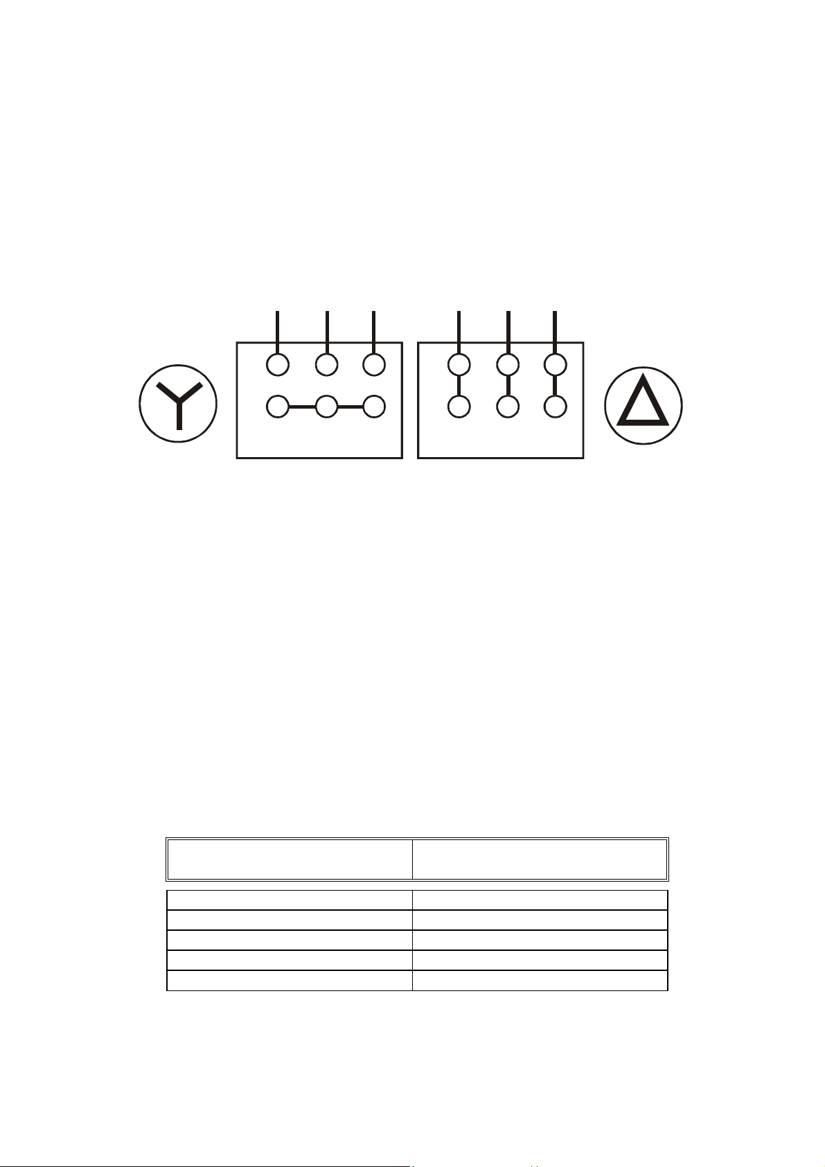
The figure below shows the star and delta connection configurations.
U V W
Z X Y
ST AR CONNECTION DELT A CONNECTION
U V W
Z X Y
fig. 8
rgf300
The
current must never exceed the rated current as given on the
regulator can control several motors connected in parallel but the absorption of the motors' total
rgf300
's specification plate.
The speeds of the motors vary at the same time though any differences in behaviour during start up and at
low speeds are due to slight differences between the motors even if they are of the same type. However, if
the required speeds of the motors are different, motors must be used with different rated speeds. Bear in
mind though that motors with very different characteristics create different electrical situations and these
may cause problems on start up and at low speeds caused by different resistances of the stators which require
different voltages on start up and at low speeds.
1.4.1 Magnetothermal protection
rgf300
Installation of magnetothermal protections is the responsibility of the installer
devices must be protected by a magnetothermal switch fitted upstream of the cutting regulators.
.
It is advisable to fit an automatic magnetothermal protection with a 'C' intervention curve having the
following capacity:
magnetothermal
RGF 300 models
carrying capacity
rgf 312 20 A
rgf 320 30 A
rgf 325 36 A
rgf 340 60 A
rgf 360 80 A
Table 2
RGF 300
13/53
Page 14
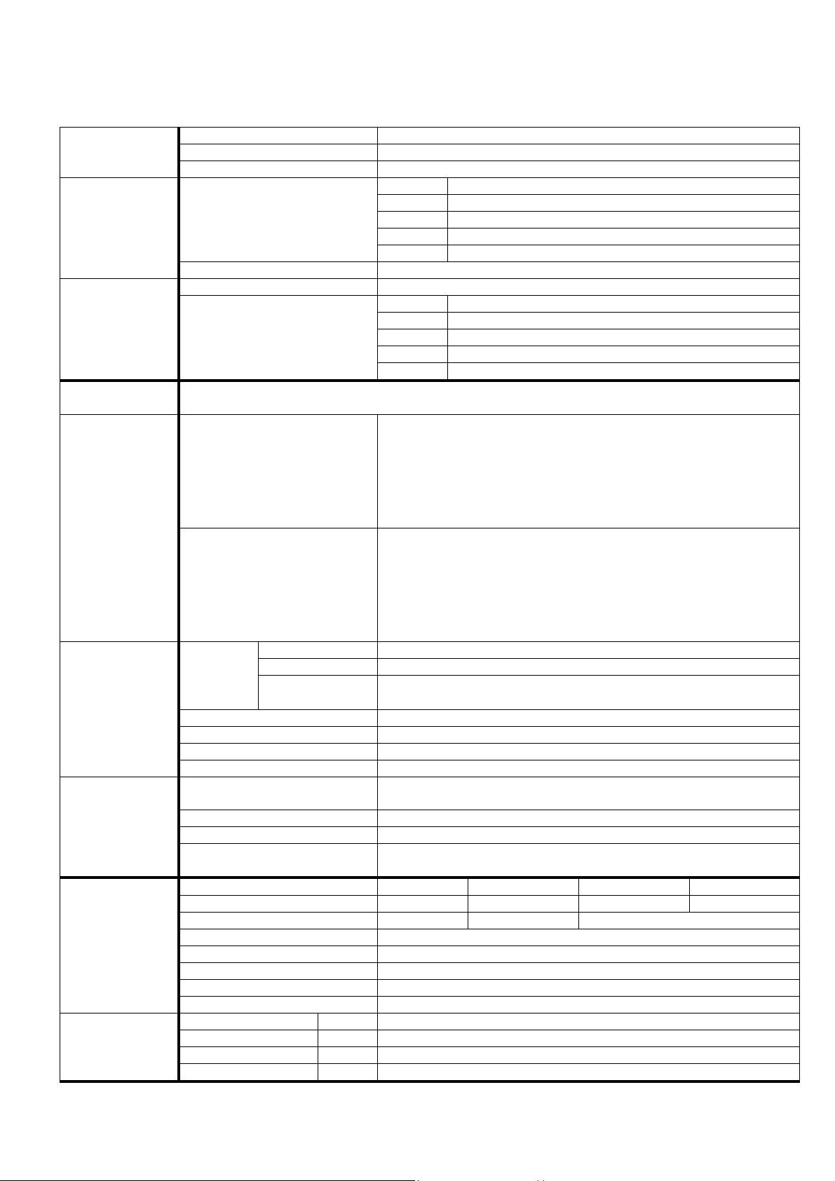
1.5 rgf 300 TECHNICAL C
Voltage
UPPLY
S
Frequency
Overvoltage protection for installation Category II (
URRENT
C
Rated
Overload
Control circuits
OWER
P
O
PRINCIPLE
PERATING
Thermally dissipated
Totally controlled three-phase cutting, with compensation for inductive loads and motors, without need for
connection to NEUTRAL
POWER unit
M , V
PERATING
O
CHARACTERISTIC
(Vers.
)
Regulator
M , V , X , Y
(Vers.
Vers. M Two
Vers. V Two
Vers.
NPUT
I
SIGNALS
Control
Heat protection
Start/Stop
Automatic/Manual
Set-Point 1 / Set-Point 2
Transducer supply
UTPUT SIGNALS
O
Potentiometer supply Two
Auxiliary control
RL1
service relay
Version & Input M: 0-20 mA V: 0-10 Vdc X: +10/+60°C Y: -20/+20°C
Target value
DJUSTMENTS
A
AND
RESETTINGS
P
Proportional range
Minimum limit / Cut-Off Adjustable from
Maximum limit Adjustable from
Acceleration ramp Adjustable from 1” to
Direct/Reverse presetting Action mode of input prevailing over output :
Prevailing input presetting Selection mode for prevailing input :
INE ALARM
LED
SIGNALLING
AC L
LARM
T.K. A
RL1 ON Green
ANUAL MODE
M
ON Red
ON Red
ON Yellow
HARACTERISTICS
420V
50 Hz (60 Hz
RGF 312
RGF 320
RGF 325
RGF 340
RGF 360
200%
10VA
RGF 312 72 W @ 12A
RGF 320 120 W @ 20A
RGF 325 150 W @ 20A
RGF 340 240 W @ 40A
RGF 360 360 W @ 60A
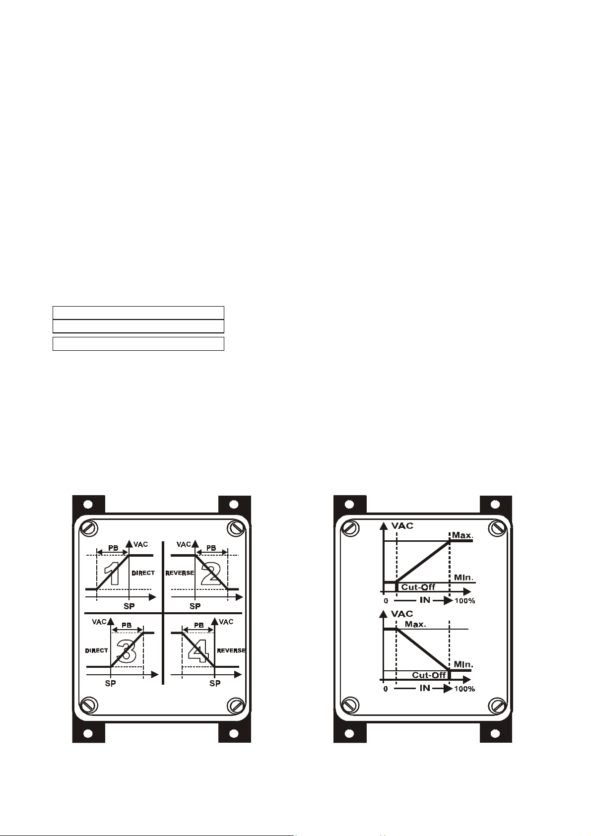
The output voltage depends on the control signal prevailing between the
two available at the inputs, which is chosen by means of the preestablished mode, according to the specific appliance regulating curve.
The action can be :
DIRECT
REVERSE
Standard Config.
The output voltage changes to keep set to the target point, selected with
the Set-Point, the quantity measured by the transducer prevailing
between the two available at the inputs, which is chosen by means of the
)
X, Y
pre-established mode (greater or lesser in value).
The action mode, either
the controlled quantity, transducer characteristic and load action.
Standard
Two
25°C)
O
O
O
O
Two
from short circuit
0-10V / 1 mA
NO/NC
of :
Signals locked state due to absence of one supply phase
Signals locked state due to motor thermal protection NC contact opening
Signals
Signals “
AC
+/- 10 %
three-phase (
)
4 KV
12 A
20 A
25 A
40 A
60 A
up to
up to
up to
up to
up to
50°C
environment, over decrease by
50°C
environment, over decrease by
50°C
environment, over decrease by
50°C
environment, over decrease by
50°C
environment, over decrease by
of the rated current (max.
, with the output increasing as the input increases, or
,
with the output decreasing as the input increases.
: output increasing as the controlled variable increases
direct
: output increasing as the controlled variable increases
0-20 mA, Ri = 100 hom
analog inputs, priority to the greater std.
0-10 Vdc, Ri = 10 khom
kohm
analog inputs for the
, priority to the hottest sensor std.
N/OFF
input, motor protection NC thermal contact
N/OFF
N/OFF
N/OFF
: Off Vin=0 =
input
Off (Vin=0) =
input:
Start /
input for Set-point 1/2 commutation (Only with
+22Vdc (-10% / +20%) 40 mA
+10Vdc / 5 mA
stabilized outputs
analog output for cascade control of other
relay contact, free from potential, for separate or joint signalling
alarm signals absent / start enabling / voltage supply
0 ... 20 mA 0 … 10 Vdc +10 ... +60 °C -20 ... +20 °C
0.4 … 4 mA 0.3 … 3.5 Vdc 3 … 30 °C
0%
to
100%
100% to 0%
10”
RL1
service relay energised state
ANUAL
M
” operation state at fixed speed
230V
AC
and
500V
AC
on request)
)
0.6 A/°C
1.0 A/°C
1.2 A/°C
1.8 A/°C
2.5 A/°C
10”
every 3’)
reverse,
or
is chosen in consideration of
analog inputs, priority to the greater std.
NTC
sensors supplied (
N
O
(
Automatic /
IN
=24V
V
N
IN
O
V
(
) : Stop
=24V
)=Manual
10KΩΩΩΩ @
PB1064
)
non-stabilised outputs, protected
SLAVE
units
greater
Direct or Reverse
smaller
/
RGF 300
14/53
Page 15
ROTECTIONS
P
ASE
C
NSULATION
I
EMPERATURE
T
UMIDITY
H
NSTALLATION
I
LECTRICAL
E
CONNECTIONS
ECHNICAL
T
STANDARDS
RH < 85%
Continually checks presence of the three mains phases; when one phase
Mains surveillance
EMC integrated
mains filter
Overvoltage protection According to
is absent, it stops the appliance and switches on the “phase absent” alarm
signal LED (
According to
ISM
appliances directly connected to low voltage power mains
AC LINE ALARM
EN 55011 (CEI 110-6
EN 61000-4-5
RGF 312 286 x 201 x 130 mm 4.0 kg
RGF 320 351 x 237 x 181 mm 5.5 kg
Dimensions and Weight
RGF 325 351 x 237 x 201 mm 8.0 kg
RGF 340 416 x 318 x 178 mm 11.0 kg
RGF 360 460 x 318 x 220 mm
Materials
Degree of protection
GW-Plast 120°C
IP 55
and black anodised aluminium
Environmental pollution Strong pollution
Fire resistance Category D
Case Class
Control circuits
Working
Storing
Vertical wall-mounting only, with
SIGNAL
RGF 312
POWER
RGF 320
RGF 325
RGF 340
RGF 360
89/392/EEC
73/23/EEC
Directive
Directive
I
(use of earthed protection cable)
4000V
between control input and mains voltage components
-20 T 50
-30 T 85
N° 4
(from –20°C to + 50°C)
(from –30°C to + 85°C)
∅∅∅∅ 6
mm. holes (RGF350 with
Trailing cable with rated cross section
Trailing cable with rated cross section
Trailing cable with rated cross section
Trailing cable with rated cross section
Trailing cable with rated cross section
Trailing cable with rated cross section
CEI-EN 60204-1
: “ Safety of machinery”
(93/68)
89/336/EEC
Directive
EN 50081-2
EN 50082-2
EN 55011
EN 55011
ENV 50140 (IEC 801-3
ENV 50141
IEC 801-4
IEC 801-2
Generic standard for industrial environment emission
Generic standard for industrial environment immunity
class B, for radiated disturbance
class B, for conducted disturbance
for conducted susceptibility on the signal lines
for fast transients (burst / high-frequency disturbance)
for electrostatic discharge (
Table 3
)
) Class B:
: overvoltage Category
II (4 KV)
17.0 kg
N° 4 ∅∅∅∅ 8
slotted holes)
1.5 sq mm / 22-14 AWG Cu
2.5 sq mm / 20-12 AWG Cu
4.0 sq mm/ 24-10 AWG Cu
10 sq mm / 20-6 AWG Cu
10 sq mm / 20-6 AWG Cu
10 sq mm / 20-6 AWG Cu
) for susceptibility (on the supply)
ESD
)
RGF 300
15/53
Page 16
2.0 ELECTRICAL CONNECTIONS
2.1 POWER CARD ELECTRICAL CONNECTIONS
For supply and load connection, reference should be made to the diagrams shown in
section of the cables is adequate to the connected load .
The power cables (supply and load) must be installed separately from the control cables (analogue inputs and
ON-OFF inputs/outputs) keeping the maximum distance possible between the conductors.
Do not place power cables with signal cables in the same raceway. If the cables cross one another,
ensure it is at 90°.
ATTENTION : connect the earth conductor to the screw placed purposely beside the dissipator. Use
heat resistant cables able to withstand temperatures greater than 90°C.
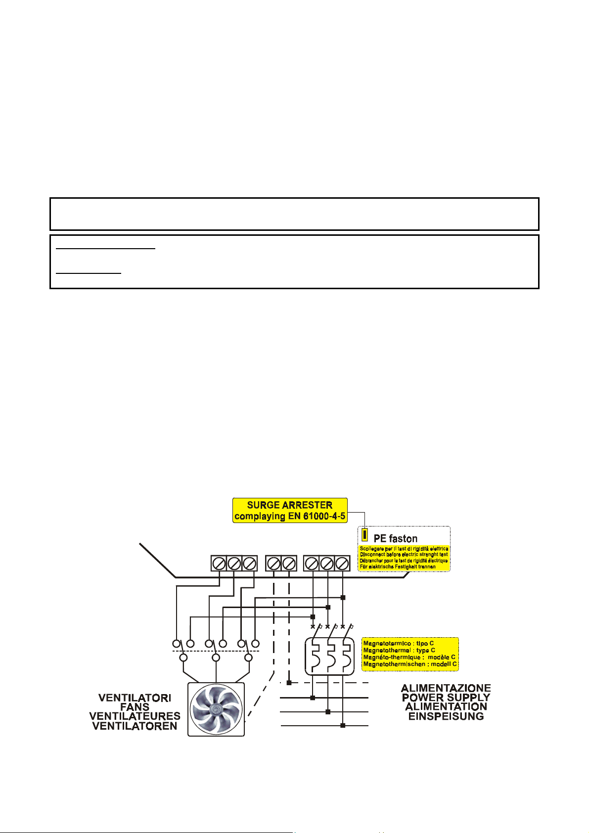
SURGE ARRESTER : electric protection placed between the regulator supply and the earth to protect
the device from transitory mains excess voltage.
ATTENTION : disconnect the PE faston contact from the earth reference, in the '
STRENGTH TEST
’.
The
rgf300
regulators allows connection of three-phase loads
without requiring connec tion of the
This simplifies installation and facilitates the star or delta load configuration.
It is advisable to provide a by-pass switch to allow load activation even when the cutting regulators is faulty
emergency by-pass
(
).
When connecting the by-pass, the following precautions should be taken into consideration:
i) connection made through the by-pass switch must keep phase correspondence unaltered so as to
avoid destructive shortcircuits and maintain the motor's sense of rotation.
ii) before supplying the load with maximum voltage, supply to the regulator should be disconnected,
therefore:
it is advisable to use a three-position manual switch as a commutation device
••••
if automatic commutation is carried out by means of contactors, make sure there is some delay (at
••••
least 2 seconds) between regulator disconnection and load activation operations.
Electrical connection of the supply and load,
for
rgf300
regulators is shown in
BY-PASS
fig. 9
U V W PE R S T
PE
L1
L2
L3
fig. 8,
makin g sur e the
ELECTRIC
NEUTRAL
.
RGF 300
16/53
Page 17

fig. 9
RGF 300
17/53
Page 18

y
2.2 ELECTRICAL CONNECTIONS, ANALOGUE INPUT SIGNALS
The connections for the control analogue inputs are described below.
They can be connected to the MA terminal board, in particular:
MASTER
MASTER
SLAVE
version Control signals in current (mA) or voltage (
version Active sensors with control in current (mA) or voltage (
version
NTC
sensors with control in
°C ( 10 kohm @ 25 °C
Vdc
)
Vdc
)
)
By connecting the second sensor it is possible to obtain regulation control on the basis of the
SIGNAL VALUE
(STANDARD version) provided by one of the two sensors.
REATER
G
Warning :
terminal for supply to
There is also a control output available on the terminal board to pilot the
when two active type sensors with current or voltage output are connected, use the +V
+22 Vdc / 40mA (MA 3
for
IN 1
and
MA 7
rgf
IN 2
for
)
unit, single phase or three
phase, that executes regulation on differentiated loads using the same automatic regulation parameters of the
rgf300
main
.
CONNECTIONS
Trailing cable with rated cross section
1.5 sq mm / 22-14 AWG Cu
Alarm
Rela
RL1
0 - 20
mA
0-10
Vdc
RGF-MEIRGF-MEI
SLAVE
1 2 3 4 5 6 7 8 9 10
NC
NO
S1 S2 TK
S3
COM
SLAVE
SLAVE
ALARM - RELAY
NC NA Com
SLAVE
8
RL1
OFF
9
10
GENERAL ALARM
SELECTIONS
ON 1 ON 2 ON 3
ON 1
ON 1
ON 2
ON 2
ON 3
ON 3
rgf300rgf300
1 2 3 4 5 6 7 8 9 10
M
4 - 20
mA
1 2 3 4 5 6 7 8 9 10
V
0 - 10
Vdc
1 2 3 4 5 6 7 8 9 10
X
Y
NTC
4 - 20
mA
0 - 10
Vdc
NTC
1 2 3 4 5 6 7 8 9 10
M
V
X
Y
RGF-MEI
RGF-MEI
SLAVE
SLAVE
SLAVE
SLAVE
1 2 3 4 5 6 7 8 9 10
M
0 - 20
mA
1 2 3 4 5 6 7 8 9 10
V
0-10
Vdc
1 2 3 4 5 6 7 8 9 10
V
1 2 3 4 5 6 7 8 9 10
M
V
fig. 10
ON 1
ON 2
ON 3
rgf300
RGF 300
18/53
Page 19

One of the main applications of the
is modulated to keep temperature or pressure constant as a work point for one or more refrigerating circuits
(condensator or evaporator mode).
STANDARD
In the
Directions are given below for connection or calibration of
temperature sensors and other possible applications for
2.2.1 Connection of XSK pressure transducers (4-20 mA)
The table below lists the information necessary for calibration of the
referred to the Centesimal Commutators (
with the position of P2.
Set-Point SP /
condition, the fan reaches maximum voltage in output (P4) coinciding with the work
P3 for 4-20m A,
SP / P3 Trimmer Centesimal Switch
M0
m
Setting
Trimmer
0
m
0
m
0
m
(*)
analogue inputs, corresponding to the mA control signal generated by the
Fig. 11
regulation controls.
GND
OUT
GND
GND
c
mA V(*)
m 4 0.4 0.00 0.00 0.00 00 m 0.4 0.37 0.62 0.75
M
c
M
5 0.5 0.93 01.56 01.87 06
6 0.6 1.87 03.12 03.75 12
7 0.7 2.81 04.68 05.62 18
8 0.8 3.75 06.25 07.50 25
9 0.9 4.69 07.81 09.37 31
10 1.0 5.63 09.37 11.25 37
11 1.1 6.56 10.94 13.12 44
c 12 1.2 7.50 12.50 15.00 50 c 2.1 1.94 3.28 3.93
13 1.3 8.44 14.06 16.87 56
c
c
Column V gives the voltage values legible with a multi meter (
14 1.4 9.38 15.63 18.75 62
15 1.5 10.31 17.19 20.62 68
16 1.6 11.25 18.75 22.50 74
M
17 1.7 12.19 20.31 24.37 80
18 1.8 13.13 21.88 26.25 87
19 1.9 14.07 23.44 28.12 93
M 20 2.0 15.00 25.00 30.00 99
shows the connection of two pressure transducers plus the type of operation (standard) and the operating
10
PRESSURE TRANSDUCER
9
10V
+V
8
7
6
IN 2
10V
+V
5
4
3
2
IN 1
1
4-20mA
0-10Vdc
START
position
rgf300
series regulators is the control of voltage and speed of rotation of fans. This
rgf300
regulators with
direct or remote regulation
Com
.) or Trimmer (
Trim
.), and for calibration of the
setting with
0-15
bar
ACCURACY
+/- 3% FS
XSK 2
XSK 1
0-25
bar
0-30
bar
Tab. 4
N°
20Vdc
Set-point
active pressure sensors, NTC
.
Set-point (page 34
Proportional Band PB / P2 setting for
) with the position of P3
Proportional Band
4-20 mA pressure transducers
Mm
c
Mm
c
Mm
c
scale limit) on the IN/
4-20mA
Mm
START
position
c
Set.
Trim
mA
0-15
bar
0-25
bar
M 4.0 3.74 6.24 7.50
Gnd
terminals of the
transducer in regulation.
WARNING :
do not invert the transducer
cables (IN / +V) when
connection is made to terminals
1/3 and 5/7 as the transducer
may be damaged.
ATTENTION :
at standard configuration
P3/Set-point
fig. 11
max. output fan
=
.
0-30
bar
RGF 300
19/53
Page 20

2.2.2 Connection of NTC temperature sensors (10kohm @ 25 °C)
Two versions of
X
•
for scale
Y
•
for scale
NTC
temperature sensors are available for
+10 °C to +60 °C
- 20 °C to +20 °C
The table below lists the information necessary for calibration of the
P3
referred to the centesimal Commutators (
Proportional Band
with the position of P2.
Com
Setting of work point SP / Set-point P3 with NTC probe
rgf300
models:
Set-point (page 34
.) or Trimmer (
) with the position of
Trim
.), and for calibration of the
Proportional Band PB/P2
SP > Trimmer P3 SP > Centesimal switch with NTC probe
Mm
Mm
RIMMER
T
SETTING
Mm
c
Mm
c
Mm
START
c
c
position
m
X (°C)
10°/60°
Y (°C)
-20°/20°
6° -22° 00 10° -20° 3 °C
30 25° -8°
c
35° 0° 50 35° 00° 18 °C
START
position
CENTESIMAL
SETTING
10 15° -16°
20 20° -12°
40 30° -4°
60 40° 4°
70 45° 8°
80 50° 12°
N°
X (°C)
10° / 60°
Y (°C)
-20°/ 20°
Mm
START
position
c
RIMMER
T
SETTING
c
Mm
m
Mm
c
c
Mm
For X & Y
Skale
90 55° 16°
c
Connection of the two
Also shown is the type of operation (standard) and operating regulation controls.
Master X for scale +10 C° to +60 C° Master Y for scale -20 C° to +20 C°
M
64° 23°
NTC
99 60° 20°
sensors is shown in
Tab. 5
fig. 12
below.
c
M
30 °C
GND
OUT
10V
+V
10
9
8
7
NTC probe (10 kohm a 25 °C)
NTC
°C
T. C.
Airflow = 35"
NO-Air = 70"
ATTENTION :
at standard configuration
P3 / Set-point
output fan
max.
=
GND
IN 2
10V
+V
GND
IN 1
6
5
4
3
NTC 2
NTC 1
2
fig. 12
1
RGF 300
20/53
Page 21

2.2.3 Connection of other sensors and control signals
Active sensors with : 0-20 / 4-20 mA current output (M vers.), and
0-10 Vdc voltage output (V vers.)
Connection can usually be made to the
control signal (
If the sensors have an earth (
supply), they can be directly connected to and supplied by the
The diagram below shows the connection of two differential pressure transducers used to maintain constant
pressure / air delivery from a fan in a controlled air flow plant (laminar flow); also shown is the type of
operation (standard) and the operating regulation controls.
0-20 mA
) or voltage output (
Gnd
rgf300
) as well as a signal (IN) reference, and they accept a
regulator with one or two active sensors, with current output
0-10 Vdc
) with conductors having two or three wires.
+24Vdc
rgf300
regulator (
fig. 13
).
(max.
40 mA
GND
OUT
10V
+V
GND
IN 2
10V
+V
GND
IN 1
10
9
8
7
6
5
4
3
2
1
+
DIFFERENTIAL
4-20mA
0-10Vdc
- Refrigerant
- Water
and
- Air Oil
- Vapor
- General Purpose
+
Differential
Transducer
+
Differential
Transducer
fig. 13
_
_
RGF 300
21/53
Page 22

2.2.4 Remote connection for a current (mA) or voltage (Vdc) control signal
Connection of an external control unit (for SLAVE M, V)
If regulator control from an external unit is required, choose one of the following versions:
SLAVE M
SLAVE V
when the external control unit uses a current control signal (
when the external control unit uses a voltage control signal (
This configuration allows a grid of several regulators to be controlled via a single regulation control signal in
either mA or Vdc, even if the regulators are a mixture of single phase and three phase.
It is therefore possible to control totally and automatically several ventilation units and, if necessary, to
release one or more regulators from automatic regulation that, using a local manual control signal (only with
0-10 Vdc
control), are regulated to the requested voltage.
The number of inputs available for differentiated control is 2 with priority going to the greater value.
fig. 14
See
for the layout of the connections.
0-20 mA
0-10 Vdc
), or
).
GND
OUT
10V
+V
GND
IN 2
10V
+V
GND
IN 1
SLAVE 'M' MODE
10
9
8
7
AUT OM ATIC CONT R OL
0-20mA
1
2
6
5
4
3
AUT OM ATIC CONT R OL
0-20mA
1
2
2
1
mode
on off
mode
on off
SLAVE 'V' MODE
GND
OUT
10V
mode
set
CFI
on
off
+V
GND
IN 2
10V
mode
set
on
CFI
off
+V
GND
IN 1
10
9
8
7
6
5
4
3
2
1
MANUAL SPEED
MANUALE CONTROL
0-10Vdc
AUT OM ATIC CONT R OL
0-10Vdc
1
2
100%0%
mode
mode
on off
on
CFI
off
RGF 300
22/53
set
Page 23

fig. 14
RGF 300
23/53
Page 24

2.2.5 Connection of the rgf MULTIDRIVER control
In this configuration, the
MA 9 (OUT)
the
The control output controlled by jumper J6 allows a signal to be sent to several
The signal takes account of the work settings on the main
Using a single control / sensor, it is therefore possible to control several single or three phase regulation
units, that act both simultaneously and proportionally, starting from the transmitted regulation control
signals.
Each unit can be used singly with other work limits (
The electrical connection and controls available are shown in
GND
OUT
10V
+V
GND
IN 2
10V
+V
GND
IN 1
and
10
9
8
7
6
5
4
3
2
1
rgf300
MA 10 (GND)
regulator is able to guide other single or three phase
IN1 GND
1 2
300
terminals.
IN1 GND
1 2
100
MEI
mA
Vdc
NTC
MEI
mA
Vdc
NTC
MIN
IN1 GND
1 2
rgf300
MAX
and
fig. 15
.
OUTPUT
.
SLAVE
).
NTC
NTC
NTC
NTC
fig. 15
Connection of the
With this module it is also possible to increase the number of sensors (max. 16), which either use current (
20mA
), voltage (
Four sensors can be connected to this module; the control signal automatically selected is the one with the
greatest value
For more information, consult the user manual for regulator
rgfMEI
0-10Vdc
and as this module is supplied separately.
expansion module is also shown in
) or kohm (
NTC sensor
), that can be connected to the regulator.
fig. 15
rgfMEI
.
.
rgf
regulators through
(M or V) units.
mA - Vdc
mA - Vdc
mA - Vdc
mA - Vdc
0-
RGF 300
24/53
Page 25

2.3 ELECTRICAL CONNECTIONS, ON-OFF INPUTS/OUTPUT
This paragraph describes the connections to the auxiliary
S1 - S2 - S3
available on the ‘MB’ terminal board for which the electrical connection is made with
and
TK,
ON-OFF inputs / output
POTENTIAL
0-
cables.
Also described is the operation of the
CONNECTIONS
Trailing cable with rated cross section
RL1 ALARM
relay and its use based on jumper
1.5 sq mm / 22-14 AWG Cu
J14
.
2.3.1 Operating selection
The operating selection is obtained by activating the
1/3, 2/3, 4/5
board.
Fig. 16
In particular:
S1
S2
S3
shows an example of connection using switches and safety devices.
indicates a
normally open (NO)
switch for commutation from
indicates a NO contact for activation/inhibition of operation (
represents a NO contact to activate commutation from
Set-point 1
AUTOMATIC
remote ON-OFF
N.B. : this control is only operative if the RGFPB10640 optional card is present on the regulator
TK
indicates a
normally closed (NC
) safety device, e.g. a
which would halt operation if were open (only if
RL1
TK 2
TK 1
STOP 2
STOP 1
GND
AUT-MAN
SP1 - SP2
10
9
8
7
6
5
4
3
2
1
COM
NO
NC
TK
S2
S1
S3
RL1 ON
GENERAL
ALARM
OFF
REMOTE
OFF
CONTACT
OFF
CONTACT
OFF
J15=ON2
RL1
HEAT PROTECTION
).
9
8
7
COM
NO
NC
TK
10
6
5
S2
4
3
2
1
S1
S3
fig. 16
6/7
and
terminals on the 'MB' terminal
MANUAL
to
);
Set-point 2 (SP1 – SP2
to
positioned on the motor,
RL1 ON
GENERAL
ALARM
ON
REMOTE
ON
CONTACT
ON
CONTACT
ON
rgf
operation.
)
signal
RGF 300
25/53
Page 26

S1: AUT / MAN (MB 2 – MB 3 terminals)
S1 = OPEN operation with variable speed regulation (Led heat-pump = OFF)
S1 = CLOSED MANUAL operation at fixed speed (Led heat-pump = ON)
The S1 contact allows the regulation to be commutated from "AUTOMATIC OPERATION" (power
supplied according to the control signal) to "MANUAL OPERATION" with fixed supply power.
Activation of this function is displayed by the
Application example :
WINTER / SUMMER OPERATION
heat-pump Led
of heat pumps.
lighting up.
The fans, connected to the regulator, can be activated depending on the temperature or pressure detected; or,
by switching
0%)
, for the required time.
CALIBRATION
the P7 trimmer to the desired voltage; then open S1
This will reset the automatic speed regulation on the basis of the control signal.
S1= CLOSED
, voltage to the fans can be kept constant, equal to the value set with
: switch the S1 contact to
CLOSED ( Led hea t-pump = ON)
(Led heat-pump = OFF)
.
and regulate the position of
P4 (100% -
The operation described here can be achieved by means of electromechanical devices. However it is
extremely simple if the cutting regulators is controlled by an external regulator (e.g. Energy Light - type
Eliwell
S2: STOP (MB 4 – MB 5 term inals)
), which can automatically control the S1 contact.
S2 = OPEN Regulator operational
S2 = CLOSED Operation stop
With S2 = CLOSED operation of the cutting regulators is stopped via a remote contact.
This is useful, for example, to stop fans during defrosting or to link fan operation to activation of a central
unit (e.g. compressor) or an alarm (e.g. max./min. temperature).
S3: SP1 / SP2 (MB 1 – MB 3 terminals)
S3 = OPEN Automatic regulator operation with SET-POINT 1
S3 = CLOSED Automatic regulator operation with SET-POINT 2
S3
The
With S3 = OPEN, the regulator works with
contact allows the reference Set-point to be commutated from
SET-POINT 1
With S3 = CLOSED, the regulator works with
Activation of this function is displayed by the
.
SET-POINT 2
SP1
and
SP2
.
Leds lighting up on the optional
SP1
to
SP2.
RGFPB10640
card.
This function is useful, for example, for day / night or winter / summer operations.
Selection is made by means of an external contact in automatic or manual commutation mode.
N.B. : this control is only operative if the optional RGFPB10640 card is present on the regulator.
TK: TK1 – TK2 (MB 6 – MB 7 terminals)
TK = CLOSED Regular operation (Led TK
TK = OPEN Operation stop (Led TK
Intervention of an external safety device opens a
Led TK
ALARM
(ON)
is lighted up.
In plants with fans in parallel, individual protection devices must be used for each motor connected so as to
reduce the risk of a total stop.
To restore normal conditions (
For operation with
J15=2,
the configuration required is :
RESET
), see the position of jumper
ALARM
ALARM
0 V
= OFF )
= ON )
potential contact and halts operation of the regulator.
J13
.
MB 6/7 = NC
RGF 300
26/53
Page 27

RL1: ALARM relay (MB 8-9-10 terminals) with J14 selection jumper
RL1
The
of the operating status.
For the operation mode of this output relay, configure jumper
the table below:
relay is mounted on the
POWER SUPPLY
control card
. The relay has a commutation contact for external signalling
J14
so that all alarms are enabled, as shown in
T.K. STOP
FAN SPEED
J14 RL1
R S T
(S2)
U V W
ON ON ON Unable Unable O.K.
ON1
OFF OFF OFF Unable Unable K.O.
ON ON ON OFF Unable O.K.
ON2
OFF OFF OFF ON Unable K.O.
ON ON ON OFF ON O.K.
ON3
OFF OFF OFF ON OFF K.O.
Besides relay RL1 in rest conditions,
J 14
:
ON1 ( standard = factory selection).
ON2
ON3
RL1
OFF
8
ALARM - RELAY
NC NA Com
9
fig. 17
10
Table 6
shows the three positions for:
GENERAL ALARMS
SELECTIONS
ON 1 ON 2 ON 3
ON 1
ON 2
ON 3
fig. 17
ON 1
ON 2
ON 3
rgfrgf
ON 1
ON 2
ON 3
rgf
RGF
RGF 300
27/53
Page 28

3.0 COMMISSIONING PROCEDURE
Having carried out the electrical connections to the regulator, it is time to perform the configuration,
regulation and commissioning operations for the
It is important to remember that the settings of the
configuration or the operating mode of the regulator set in the factory (check the label on the right side of the
casing).
3.1 Jumpers
This paragraph describes the preset functions of the programming
of the following types The term "
Jumper
" refers to the moveable element which connects two (2) contacts.
2, 3, 6
10 contacts
and
rgf300
(see
regulator by following the procedure below.
jumpers (Jn
fig. 18
).
) are only to be modified to change the
jumpers
; the jumpers used on the card are
3 contacts
3 contatti
pos.
1
1 2 1 2
2 contacts
2 contatti
ON
pos.
1 2 1 2 3
fig. 18
For 2 contact jumpers, the function is activated when the
jumper
For 3 contact jumpers, there are two selection types:
•
position ‘1’ i.e. the middle jumper connected to jumper no. 1
•
position ‘2’ i.e. the middle jumper connected to jumper no. 2
For 6 contact jumpers (
J5
For 10 contact jumpers (J6), there are 5 selection types (pos.
The main jumpers on the
J1
J1 = ON1
J1 = ON2
J2
J2 = ON1
J2 = ON2
Selects the work field of the
P3
with control from active sensors for
P3
with control from active sensors for
Activates the standard
this control is only operative if the RGFPB10640 card is present on the regulator)
(
Set-point (P3
Set-point (P3
J14
and
), there are 3 selection types (pos.
1, 2, 3, 4, 5
rgf300
cutting regulators
Set-point P3
control card
:
4-20mA
0-10 Vdc
Set-point
), with trimmer mounted on the
or the auxiliary, optional, double digital
PB 1018/3
), with double digital commutators in 99 positions, mounted on the
RGFPB10640;
it also inhibits operation of P3 (standing) when in the
J3
J3 = ON1
J3 = ON2
Selects the operation of the regulator at the
Set-point (P3
Il
Set-point (P3
) corresponds to the minimum control value of the fan
) corresponds to the maximum control value of the fan
The standard position is ON2.
Set-point
3 contacts
3 contatti
pos.
2
6 contacts
6 contatti
pos.
is present (position ON).
1, 2, 3
fig. 18
);
shows position 1.
).
are described below.
NTC (ohm
or
) sensors for
basic regulation card
SLAVE
:
configuration,
1
°C
Set-point
J2 = ON2
:
RGF 300
28/53
Page 29

J4
J5
J5 = ON1
J5 = ON2
J5 = ON3
J6
J6 = ON1
J6 = ON2
J6 = ON3
J6 = ON4
J6 = ON5
J7
J7 = ON1
J7 = ON2
J8 = ON
J9 = ON
J10
J10 = ON1
J10 = ON2
J11
J11 = ON1
J11 = ON2
J12
J12 = ON1
J12 = ON2
Selects the operating mode of output
Selects the work field of the
P2
scale for control input with
P2
scale for control input with active sensors from
P2
scale for control input with activ e sensor s from
Selects the type of output control sig nal from the
0-10 V
10-0 V
Control signal with
Signal to indicate the shift of the input signal from the
signal proportional to the power output (for
signal proportional to the power output (for
OFFSET
Proportional Band
(for
Input signal (greater or lesser) (for
Selects the size of the value in % C (of control) to display on the portable unit:
displays control signal %C with
displays control signal %C without
Selection
J 8
If
is
Selection
J 8
If
is
Selection
J 9
If
is
Selection
J 9
If
is
DIRECT
for '
ON,
the voltage supplied to the fans increases with the inc rea se in input si g n al.
REVERSE
for ‘
ON,
the voltage supplied to the fans increases with the decrease in input signal.
REVERSE
for ‘
ON,
the voltage supplied to the fans increases with the decrease in input signal.
DIRECT
for '
ON,
the voltage supplied to the fans increases w ith the inc rease in in put signal.
' operation with
‘ operation with
‘ operation with
' operation with
MA 9/10
NTC (ohm
J4 = 1
J4 = 1
) sensors for °C (range
)
)
OFFSET
OFFSET (0 – 100%)
J3 = ON1
J3 = ON2
J3 = ON1
J3 = ON2
in combination with jumper
°C, mA, Vdc
in
:
3 – 30 °C)
4-20 mA
0-10 Vdc
rgf300
(range
(range
on terminal
0.3 – 3.5 Vdc
J4 = 2)
J4 = 1
)
Set-point
(for
J6.
0.4 – 4 mA
MA 9/10
J4 = 1
)
The selection of one excludes the other.
In the versions with
Selects the
selects
selects
Selects the input signal priority:
selects the
selects the
•
In the version with
with the greater °C value
Selects the type of input for use of the portable unit :
displays the voltage signal in
displays the current signal in
•
In the version with
work field of the sensor (
MASTER
SLAVE
MASTER
LESSER
GREATER
NTC
sensor, the operation of J8 and J9 with
SLAVE
or
mode for the
mode for the
value
value
NTC
NTC
operating mode:
rgf300
rgf300
sensor, selecting
V (0-10 Vdc)
mA (0-20
4-20 mA)
and
sensor, selecting
X = +10 to +60 °C
J11=ON1
J12=ON1
and
is the equivalent of selecting the sensor
is equivalent to automatic setting of the
Y = -20 to +20 °C
J3 ON1/ON2,
)
)
)
:
is inverted.
RGF 300
29/53
Page 30

J13
J13 = ON1
J13 = ON2
J14
J14 = ON 1
J14 = ON 2
J14 = ON 3
J15
J15 = ON 1
J15 = ON 2
J16
J16 = ON 1
J16 = ON 2
J17
J17 = ON 1
J17 = ON 2
Selects the
RESET
operating mode of the TK contact (terminal board
MB 6/7
):
when selected, if the TK protection intervenes, the regulator must be switched off and on
again to reset the system after the cause has been eliminated (
MANUAL RESET
).
when selected, if the TK protection intervenes, the system restarts automatically after
the contact has been reset (
AUTOMATIC RESET
).
The standard position is ON2
Selects the operation of the
when selected the relay is activ e (
when selected the relay is activ e (
and with open remote
STOP
when selected the relay is activ e (
with open remote
STOP
The standard position is ON3
.
RL1
relay:
position ON
position ON
), in the absence of alarms (
), in the absence of alarms (
control signal
position ON
), in the absence of alarms (
control signal and with
.
supply
Alarm Led = OFF
Alarm Led = OFF
Alarm Led = OFF
of voltage to the load in course.
Selects the operation of the heat protection:
when selected, the TK heat protection contact is excluded.
when selected, the TK heat protection contact must be connected to the terminal board
The standard position is ON1
Selects the type of input on the
.
IN 1
channel:
when selected, the input is activated for control signals in mA.
when selected, the input is activated for control signals in
Selects the type of input on the
IN 2
channel:
Vdc
ohms (NTC
and
sensor)
when selected, the input is activated for control signals in mA.
when selected, the input is activated for control signals in
Vdc
ohms (NTC
and
sensor)
)
)
),
WARNING !
• Check the position of jumpers 'Jn' during commissioning.
If the rgf300regulator work mode is altered (MASTER / SLAVE), refer to fig.s 19, 20, 21, 22 and 23 which
give the standard work configurations of the jumpers.
• The regulator is already set for the operations indicated on the label on the side of the casing; if modifications
are required, describe and indicate the modifications made on the TECHNICAL ASSISTANCE MODULE.
WARNING !
• The configuration with NTC temperature sensors is not compatible with other configurations.
It is not therefore possible to alter the position of the jumpers to pass from operation with NTC sensors to
operation with active sensors or control signals in mA or Vdc, nor to change the °C work field/scale of the rgf
regulator.
RGF 300
30/53
Page 31

3.2 MASTER, version M (4-20 mA), for 1 or 2 control INPUTS
P1 P2 P3 P4 P5 P6
= Soft-Start
MmmMmMmMmMmM
1
1
CN3
J1
J4
J5
J8
J9
1
J17J16
2
2
1 2
1
2
3
J10
1
2
1
2
J2
2
1
J3
2
J6
J7
1
2
HEAT
PUMP
J12J11
1
2
3
4
5
1
2
1
2
Mm
P7
P1
= Proportional Ba nd
P2
= Set-Point
P3
= max. output
P4
= min. output
P5
= Cut-off
P6
= MANUAL (mode H .P.)
P7
AC LINE
ALARM
ALARM
J13
J15
T.K.
1
2
J14
1
2
RL 1
ON
1
2
3
FL
RL1
CN2
1 2 3 4 5 6 7 8 9 10
1 2 3 4 5 6 7 8 9 10
fig. 19
3.3 MASTER, version V (0-10 Vdc), for 1 or 2 control INPUTS
P1 P2 P3 P4 P5 P6
= Soft-Start
MmmMmM
1
J1
2
CN3
1 2
J4
J5
J8
J9
1
J17J16
2
mM
1
J2
2
1
J3
2
1
J6
2
3
J10
1
1
2
2
HEAT
1
PUMP
2
mMmM
1
2
3
4
5
1
J7
2
P7
1
2
Mm
J12J11
P1
= Proportional Band
P2
= Set-Point
P3
= max. output
P4
= min. output
P5
= Cut-off
P6
= MANUAL (mode H.P.)
P7
AC LINE
ALARM
ALARM
J13
J15
T.K.
1
2
J14
1
2
RL 1
ON
1
2
3
FL
RL1
CN2
1 2 3 4 5 6 7 8 9 10
1 2 3 4 5 6 7 8 9 10
fig. 20
RGF 300
31/53
Page 32

3.4 SLAVE, version M (0-20 mA), for 1 or 2 control INPUTS
P1 P2 P4 P5 P6
= Soft-Start
Mm
MmM
m
J1
mM
1
2
1 2
1
2
1
2
J4
1
2
J5
3
J10
J8
1
2
J9
1
2
1
J17J16
2
mMmM
J2
J3
1
2
3
J6
4
5
1
J7
2
1
1
2
2
J12J11
HEAT
PUMP
P7
Mm
P1
=
P2 Set - 100% output
=
P3 standing
= max. output
P4
= min. output
P5
= Cut-off
P6
= MANUAL (mode H.P.)
P7
T.K.
AC LINE
ALARM
ALARM
J13
J15
1
2
J14
1
2
RL 1
ON
1
2
3
FL
RL1
CN2
1 2 3 4 5 6 7 8 9 10
1 2 3 4 5 6 7 8 9 10
fig. 21
3.5 SLAVE, version V (0-10 Vdc), for 1 or 2 control INPUTS
P1 P2 P4 P5 P6
= Soft-Start
Mm
m
M
mM
1
J1
2
1 2
mM
J4
J5
J10
J8
J9
1
2
1
J17J16
2
mMmM
1
J2
2
1
J3
2
1
J6
2
3
J7
1
1
2
2
J11
HEAT
PUMP
1
2
J12
1
2
3
4
5
1
2
Mm
P7
P1
=
P2 Set - 100% output
=
P3 standing
= max. output
P4
= min. output
P5
= Cut-off
P6
= MANUAL (mode H.P.)
P7
T.K.
AC LINE
ALARM
ALARM
J13
J15
1
2
J14
1
2
RL 1
ON
1
2
3
FL
RL1
CN2
1 2 3 4 5 6 7 8 9 10
1 2 3 4 5 6 7 8 9 10
fig. 22
RGF 300
32/53
Page 33

3.6 MASTER, version X or Y (NTC °C), for 1 or 2 control INPUTS
P1 P2 P3 P4 P5 P6
= Soft-Start
MmmM mM
CN3
1
2
J17J16
J1
J4
J8
1
2
J5
J9
mM
1
2
1
2
1 2
1
2
3
J10
1
2
1
2
mMmM
J2
J3
1
2
3
J6
4
5
1
J7
2
1
1
2
2
J12J11
HEAT
PUMP
P7
Mm
P1
= Proportional Band
P2
= Set-Point
P3
= max. output
P4
= min. output
P5
= Cut-off
P6
= MANUAL (mode H.P.)
P7
AC LINE
ALARM
ALARM
J13
J15
T.K.
1
2
J14
1
2
RL 1
ON
1
2
3
FL
RL1
CN2
1 2 3 4 5 6 7 8 9 10
1 2 3 4 5 6 7 8 9 10
fig. 23
rgf300
The
MASTER X
MASTER Y
version for temperature control inputs with
with temperature scale
with temperature scale
+10 to +60 °C
-20 to +20 °C.
The scale limit values for the Trimmer with P3 Set-point calibration are inverted compared to the
current (mA) and voltage (
Vdc
) scales for the active sensors.
NTC
sensors is available in two °C scales:
WARNING !
• The configuration with NTC temperature sensors is not compatible with other configurations.
It is not therefore possible to alter the position of the jumpers to pass from operation with NTC sensors to
operation with active sensors or control signals in mA or Vdc, nor to change the °C work field/scale of the
rgf regulator.
RGF 300
33/53
Page 34

3.7 Optional module for dual Set-point configuration (SP1 – SP2)
rgf300
The
using the
Insert the card in the
When the card is positioned, with
99
position
regulator can be used in versions
optional
module card
CN3
RGFPB10640
connector on the
J2=ON2
digital commutators
.
Activating the contact on terminal board
commutation is shown by the lighting up of the
MASTER M, V, X, Y
for double control Set-points.
rgf300
regulator (see the position in
, Tri mme r P3 is disabled (
MB 1/ 3
, it is possible to change the regulator's work point. The
SP1
and
SP2 Leds
with a
standing
reference dual Set-point
fig. 25
).
) and substituted by two pairs
on the card above the centesimal
commutator for setting of the Set-points.
Fig. 26
shows the
mA (bar/°C
RGFPB10640
card and the reference table for inputs in:
for pressure transducers) and
°C
(for
NTC
sensors) in the different work ranges.
SP1
0
9
8
7
6
0
9
1
1
2
2
8
3
3
7
4
5
7
4
6
5
SW1 SW2 SW3 SW4
SP1
P3
CN3
RGFPB10640
(OPTIONAL)
SP2
0
9
8
6
0
9
1
1
2
2
8
3
3
7
4
4
6
5
5
SP2
fig. 24
MA MB
P1 P2 P3 P4 P5 P6
MmmMmMmMmMmM
1
1
SP1 SP2
0
0
0
9
9
1
1
2
8
8
3
7
7
4
4
6
6
5
5
SW1 SW2 SW3 SW4
SP1 SP2
0
9
9
1
2
2
8
8
3
3
7
7
4
6
6
5
5
P3
CN3
J1
1
2
3
4
J4
J5
2
1 2
J2
2
1
J3
2
J6
1
2
3
J7
PB10640
(optional)
1
2
J9
J8
1
1
2
2
J10
1
J17J16
2
J12J11
HEAT
PUMP
CN2
1 2 3 4 5 6 7 8 9 10
1
2
3
4
5
1
2
1
2
P7
Mm
P1 = Soft-Start
P2 = Proporti onal Band
P3 = (standing for J2=2)
P4 = max. output
P5 = min. output
P6 = Cut-off
P3 = Dual Set-point
P7 = MANUAL (mode H.P.)
AC LINE
T.K.
ALARM
RL 1
ON
ALARM
1
1
2
J13
J15
J14
1
2
2
3
RL1
1 2 3 4 5 6 7 8 9 10
FL
fig. 25
by
RGF 300
34/53
Page 35

4.0 CONTROL TRIMMER
WARNING
: Before starting the regulator cal ibration phase, check the position of the
trimmers as shown in figs. 26 and 27.
The position of the trimmers marked with a spot of red paint (factory calibrated trimmers) must not be altered.
P1
Mm MmMm
fig. 26
P1
Mm Mm
fig. 27
The work parameters regulation can be divided into
definition of regulator work limits
1.
definition of regulator work field
2.
SLAVE
With
With
Range
N.B.:
MASTER
and
type regulators, the regulator calibration is completed during
type regulators,
Set-point
it is possible to read the work parameters by connecting the
keys as shown in
.
P2
STARTING configuration for 'MASTER' regulator calibration trimmers
P3
P2
STARTING configuration for 'SLAVE' regulator calibration trimmers
: the values of
: the values of
PHASE 1
fig. 28
to display the readout of the value set with the calibration trimmers.
P4
P4
is necessarily followed by
P5
Mm
P5
Mm
TWO PHASES:
P4
and
P2
and
P3
P6
MmMmMm
MmMmMm Mm
P5/P6
are defined in this phase.
HELP1
P7
P6
are defined in this phase.
PHASE 1
PHASE 2
which defines the
portable display unit; press the
P7
.
Work
%C %C%C
PB
SP
fig. 28
%C
RGF 300
35/53
Page 36

4.1 MAX. OUTPUT regulation (P4 trimmer) - PHASE 1
400
Vac
P4 100%
P4 80%
P5
%C
100% 80%
Mm
cc
Mm
Max. output
400
Vac
P4
0
M’;
setting
P4
MAX.OUTPUT
M = 100%
m = 0%
To regulate the
1)
bring the P5 trimmer (manual control of minimum voltage) to position ‘
2)
turn the P4 trimmer starting from position ‘M’ as far as the desired MAX. voltage value;
3)
bring the
MAX
.
Limits the maximum operating voltage (from 100% to 0%).
It is useful for limiting the maximum capacity or noise of the fan when turning at max.
speed.
It is set in the factory to the max. value ‘M’ which corresponds to the max. voltage
supplied to the fan and equal to 100% of the control value.
MAX. OUTPUT
P5
trimmer to minimum value ‘m’: the output voltage to the load will have the P4 value as
voltage correctly, proceed as follows:
fig. 29
4.2 MIN. OUTPUT regulation (P5 trimmer) - PHASE 1
0% 20%
Mm
Mm
%C
SP
cc
P5 20%
Min. output
setting
fig. 30
P5
.
MIN
OUTPUT
m = 0%
M = 100%
Regulation of trimmer P5 supplies the fan with a constant minimum voltage when the automatic control is
not working or the control input is disconnected.
Rotate P5 anticlockwise starting from position ‘m’ until the desired minimum voltage is reached.
Allows manual regulation of the minimum output voltage from 0 to 100%.
During the calibration starting phase, it is used to check the regulator for correct cutting
regulators and the fans for correc t rota tion.
It is also used as reference for
output voltage (P4).
CUT-OFF
P5 0%
calibration (P6) and calibration of the max.
SP
RGF 300
36/53
Page 37

g
4.3 CUT-OFF regulation (P6 trimmer) - PHASE 1
0% 20%
Mm
Mm
400
Vac
P4
%C
cc
CUT-OFF
settin
P6
C
UT-OFF
m = 0%
M = 90%
In order to adjust the
1)
turn the P5 trimmer (manual speed control) starting from position ’m’ until the desired minimum
rotation voltage is obtained;
2)
turn the P6 trimmer starting from position ‘m’ until the P6 value overlaps the
fix the P6 trimmer position exactly and check the state of the
'off' position to the 'on' position (only if
3)
bring the
voltage selected.
Adjusts the minimum voltage being supplied to the fan during automatic operation:
the fan will not be supplied with voltage lower than the predetermined value; this avoids the supply
of minimum voltage which would not be sufficient to prov ide a starting torque for the fan rot at ion.
'CUT-OFF'
P5
trimmer to minimum value ‘m’: the load will now be supplied starting from the minimum
correctly, proceed as follows:
J14 = ON3
fig. 31
);
P6 20%
P6 0%
RL1 ON
SP
P5
value;
Led wh ich mus t move from t he
RGF 300
37/53
Page 38

4.4 PROPORTIONAL BAND regulation (P2 trimmer) - PHASE 2
P2
P
ROPORTIONAL
B
AND
- mA
Vdc
-
°C
-
4.4.1 Versions with MASTER regulator operation
MASTER
In
once set, passes the fan from the maximum voltage (
P5 or P6
The P2 work field is different for different versions.
).
Trimmer P2 takes on different roles depending on the model of
- on '
- on
regulator versions the range determines the value in
Master
'Slave'
give maximum voltage to the load corresponding to the maximum control
signal sent to the regulator.
operation models (
'
operation models (M and V), trimmer P2 is set at the factory to
M,V,X,Y), P2
MAX.OUT P4
adjusts the proportional band.
mA / V / °C
) to th e minimu m set (
rgf300
of the input signal that,
chosen:
MIN. OUT
PB
for
MASTER
0.4 mA 2.1 mA 4.0 mA
MmMm Mm
4-20 mA
P4
P5
Mc m
(M)
for
MASTER
0-10 Vdc
(V)
for
MASTER
cc
0,3 Vdc 1,75 Vdc 3,5 Vdc
MmMm Mm
cc
3 °C 18 °C 30 °C
MmMm Mm
c
c
NTC °C
(X - Y)
fig. 32
cc
c
RGF 300
38/53
Page 39

Version M for 4/20 mA active sensors:
ranges from:
The current signal is tied to the scale amplitude of the transducer used.
In the case of pressure control (which occurs most frequently), the value of the
depending on the pressure transmitter scale.
Version V for 0/10 Vdc active sensors:
ranges from:
Vdc / set physical quantity
For
Versions X and Y for NTC sensors ( °C )
ranges from:
correspondence, refer to the characteristics of the sensor used.
0.4 mA
-
2.1 mA
-
4.0 mA
-
0.30 Vdc
-
1.75 Vdc
-
3.50 Vdc
-
-
18.0 °C
-
30.0 °C
-
(trimmer in position 'm' )
(trimmer in position 'c' )
(trimmer in position 'M' ).
(trimmer in position 'm' )
(trimmer in position 'c' )
(trimmer in position 'M' ).
:
3.0 °C
(trimmer in position 'm' )
(trimmer in position 'c' )
(trimmer in position 'M' ).
mA/Bar
ratio changes
4.4.2 Versions with SLAVE regulator operation
In this case, the
controller.
Trimmer P2 only determines the maximum voltage supplied to the fan corresponding to the maximum
control signal received by the regulator from the remote controller:
20 mA
10 Vdc
Starting with the trimmer in position ‘m’ and remote control at maximum (
value of the voltage supplied to the load.
It is at maximum (100%) when the trimmer is roughly in the position shown in
in mA and Vdc.
In this configuration, the
N.B
position in the factory and must NOT be altered.
for the
for the
in the SLAVE configuration the P2 trimmer is already calibrated and varnished to hold its
.:
rgf300
SLAVE M
SLAVE V
is subjected to a control signal (automatic or manual) generated by a remote
version, and
version.
DIRECT
REVERSE
or
20 mA
fig. 33
mode is determined by the external controller.
10 Vdc
or
with the control signal
), check the
100% 100%
MM
m
m
400
Vac
40% 100%
%C
20 mA 10 Vdc
Setting Max. output at
max. INPUT of mA/Vdc
fig. 33
P2
0
RGF 300
39/53
Page 40

4.5 SET-POINT regulation (models M, V, X, Y) P3 trimmer - PHAS E 2
P3
SET POINT
- mA
- Vdc
- °C
Fig. 34
shows the values and positions of the trimmers for the different ‘
It is possible to activate the
trimmer.
In the standard configuration, the Set-Point coincides with the maximum value of supply (100% or
value of P4 max. output).
The regulation scales are as follows in
•
model M : from
•
model V : from
•
model
•
model
The direction of regulation goes from
SLAVE
In
Note:
- for M versions, the regulation refers to the current control signal (mA)
- for V versions, the regulation refers to the vol tag e control signal (
- for X and Y versions, the trimmer regulation refers directly to the temperature in ºC.
It is therefore necessary to change the "
corresponding measured quantity / control signal.
X
: from
Y
: from
versions
(M
SP
OPTIONAL
SET-POINT
0 mA to 20 mA
0 Vdc to 10 Vdc
10 °C to 60 °C
-20 °C to 20 °C
V)
and
, this trimmer
(the automatic regulation start point) by activating the P3
'Master'
'm'
(low values) to
for
MASTER
4-20 mA
(M)
for
MASTER
0-10 Vdc
(V)
for
MASTER
NTC °C
(X - Y)
fig. 34
versions:
'M'
(high values).
is not operative
range
" of the sensor being used to work out the
4 mA 12 mA 20 mA
0 Vdc 5 Vdc 10 Vdc
X) 60 °C 35 °C 10 °C
Y) 20 °C 0 °C - 20 °C
MMM
STANDING
(
MASTER
Vdc
cc
cc
cc
)
even if present.
).
’ configurations.
MmMm Mm
c
MmMm Mm
c
m mm
c
During the calibration procedure, it is advisa ble to start from position
'c' so as to be positioned halfway through the work field and the
connected transducer or sensor scale.
RGF 300
40/53
Page 41

4.5.1 Centesimal SET-POINT option (mod. M, V, X, Y) P3 - FHASE 2
In the MASTER configuration, the
This plug support the
switch) in 99 setting positions.
So it’s possibl e to set two (2) working Set-point (ex.: Night / Day – Winter / Summer, etc.) with S3 switch
SP1 / SP2
(led
P3
CENTESIMAL
& DUAL
SET POINT
- mA (Vdc)
- °C
switch-on)
SIMPLY
It is possible to activate the
P3
centesimal switch (100 positions).
In the standard configuration, the Set-Point coincides with the maximum value of supply (100% or
value of P4 max. output).
The regulation scales are as follows in
•
model M : from
•
model V : from
•
model
•
model
The direction of regulation goes from
SLAVE
In
Note:
- for M versions, the regulation refers to the current control signal (mA)
- for V versions, the regulation refers to the vol tag e control signal (
- for X and Y versions, the trimmer regulation refers directly to the temperature in ºC.
It is therefore necessary to change the "
corresponding measured quantity / control signal.
RGF300
Set-point (P3
X
: from
Y
: from
versions
(M
can be chosen with the
), with double digital commutators for
SET-POINT
4 mA to 20 mA
0 Vdc to 10 Vdc
10 °C to 60 °C
-20 °C to 20 °C
V)
and
, this trimmer
(the automatic regulation start point) by activating the
'Master'
'00'
(low values) to
RGFPB1064 OPTION
versions:
'99'
(high values).
is not operative
range
" of the sensor being used to work out the
STANDING
(
Vdc
.
DUAL
Set-Point (S3
)
, even if present.
).
S3 S3
fig. 36
MB
RGF 300
41/53
Page 42

4.6 SOFT-START regulation (P1 trimmer)
P1
Soft-Start
m = 2”
M = 10”
Adjusts the rapidity with which the fan speed varies (
practice it makes the system 'slow' or 'fast' depending on the change in the automatic control
signal.
'M'
In th e
the maximum (system slow to vary).
In the
The cutting regulators is provided with a minimum
P1=m
(
position (trimmer completely turned clockwise), the variation speed is slowed to
'm'
position (minimum), speed variation is almost instantaneous ('fast' system).
) to avoid possible hunting that might be caused by an excessively slow system.
10” 2”
MM
SOFT-START
fig. 37
4.7 MANUAL regulation (P7 trimmer)
P7
MANUAL
m = 0% (o P6)
M = 100%
Adjusts the operating speed in
it allows a constant output voltage value to be set from between 100% and the
(P6), value using trimmer P7.
Once S1 is closed with a ‘ 0 V ’ potential contact, turn P7 anticlockwise starting from
position M until the desired voltage value is reached.
The standard preset position for P7 is ‘M’.
MANUAL
m
setting
mode:
'slow start'
Soft-Start
cc
'slow stop'
and
time equal to circa 2 seconds
); in
m
CUT-OFF
100% 40%
MM
m
m
400
Vac
P4
20% 40% 100%
%C
P7
cc
MANUAL output
setting
fig. 38
WARNING !
The position of trimmers marked with a spot of red paint (factory calibration)
must not be altered
P6
0
RGF 300
42/53
Page 43

5.0 HELPI 10: PORTABLE DISPLAY UNIT
All calibration operations described can easily be carried out with the portable module called
display of work parameters.
All three phase regulators in the
and MB terminal boards. After connecting the
rgf300
series are fitted with the
I
HELP
10
module, the settings made with the regulator work
parameter trimmers can be chosen and displayed, even if the
The portable
HELP
10
unit is shown in
fig. 39
with function keys described.
I
CONNECTION CABLE
TERMINAL UNIT / rgf
rgf300
CN2
connector located between the MA
is being supplied on the workbench.
HELP
I
10
for
rgf SIGNALS'
LED INDICATORS
Displays the mA values
of INPUT signals
DISPLAYS THE STATUS OF
WORKING PARAMETERS
5 - Set-Point
6 - input IN 1
9 - displays the % output
comand
SP
IN 1
IN 2
C/Off
%C
+V
PB
0-15 0-25 0-30
BAR
PREDISPOSITION LED INDICATORS
1 2 3 4
0-25
0-15
bar
bar
5 6 7 8
SP IN 1 IN 2
9 10 11 12
DIR REV
%C + V
( + ) ( - )
4-20mA0-10
+10 - 20
+60 +20
V
0-30
bar
°C
mA
Bar
°C
%
V
4-20
mA
Cut
Off
UNITS OF
MEASUREMENT
LED INDICATORS
1 - scale 0 / 15 bar
2 - scale 0 / 25 bar
3 - scale 0 / 30 bar
4 - current loop
( 4 - 20 mA )
7 - input IN 2
8 - Auxiliary
11 - selection mA mode
REVERSE (-)
10 - selection °C mode
DIRECT (+)
13 - Proportional Band
14 - UP arrow
(*) 10/11/13/14/15/16 - push bottons for Proportional Band setting (PB)
13 14 15 16
PB
12 - Vdc Power supply
for transducers
15 - DOWN arrow
16 - push botton for
PB setting
fig. 39
RGF 300
43/53
Page 44

S
UMMARY TABLES FOR USE OF THE
Technical characteristics
Supply voltage
22 V ( 18....36 V ) From the connected appliance
4 - 20 mA
Input
Layouts
0 - 10V
NTC +10...+60°C
NTC -20...+20°C
Main Set-point Units of measurement
Transducer input 1 “
Signals measured
Transducer input 2 “
% output control signal “
Transducer supply voltage “
Proportional band “
Dimensions
Weight
Screen
N
UMERIC DISPLAY
225 x 105 x 40 mm.
0.5 kg
LCD 3 ½ digit
position left of the display
LED unit
Selected input
no. 7
colour green
function indicates which signal is being displayed at any moment
position below the display
no. 8
Led unit
Regulator
set-up
colour red
function
position right of the display
Led unit
Units of measurement
no. 5
colour green
function indicate the units of measurement of the value on the display
Led
Caption Function
DIR (+)
REV(-)
Inputs Forcing
Direct operation selected for calibration of the proportional band
Inverse operation selected for calibration of the proportional band
Forced transducer inputs for calibration of the proportional band
HELPI10
DISPLAY MODULE
Can be changed via the
keyboard to:
.
0 - 15 bar
0 - 25 bar
0 - 30 bar
mA , V , bar , °C
mA , V , bar , °C
mA , V , bar , °C
% ( 0......100)
V
mA , V , bar , °C
indicate the set-up on the connected regulator, including units of
measurement and scale limits, for the following signals:
SP , IN1, IN2
.
Also indicates if the scale factor has been modifed from mA to bar
RGF 300
44/53
Page 45

g
p
COMMISIONING PROCEDURE :
Function keys > Regulation (Trimmer) > Displays
Trimmer
startin
osition
SP
(M2) (M3) (M1)
PB
P1 P2 P3 P4 P5 P6
MmmMmMmMmMmM
SP1
0
0
9
9
1
2
8
8
3
7
7
4
6
6
5
5
SW1 SW2 SW3 SW4
P3 = Set-Point
PB1064
OPZIONAL
1 2 3 4 5 6 7 8 9 10
1
4
P3
SP2
0
0
9
9
1
2
3
1
2
8
2
8
3
3
7
7
4
4
6
6
5
5
SP2SP1
1
2
SP
J1
J4
J8
J17J16
J5
J9
1
2
1 2
%C
1
2
1
2
1
2
3
J10
1
2
J11
1
2
fig. 40
J2
J3
J6
1
2
HEAT
PUMP
J7
1
2
J12
CN2
1
2
3
4
5
1
2
Cut
Off
P1 = Soft-Start
P2 = Proportional Band
P4 = max. output
P5 = min. output
P6 = Cut-off
P7 = MANUAL (mode H.P.)
T.K.
AC LINE
ALARM
ALARM
P7
Mm
%C
1 2 3 4 5 6 7 8 9 10
RL 1
ON
FL
RL1
RGF 300
45/53
Page 46

RGF 300
46/53
Page 47

How to use the HELPI10 display m odule
I
Connect the
•
HELP
regulator powered up and operating
Check the
•
If desired, for
•
Leds
10
unit to the regulator to calibrate using the supplied cable; this can be done with the
but without transducers or sensors connected
corresponding to the input set-up of the regulator are lit up correctly.
4-20 mA
inputs, choose the scale in
bar
corresponding to the pressure transducer used. There are
three choices:
Transducers with range
Transducers with range
Transducers with range
Set-point
•
Input 1
•
Input 2
•
Cut-Off (N.B : Only for regulators with PB1018/4 control card)
•
0 - 15 bar
0 - 25 bar
0 - 30 bar
press key
press key
press key
Press key 5 "SP": the
measurement (
mA, bar, °C, V
The current value of the
To alter it, adjust the
Press key 6 "
measurement (
P3
IN 1
": the
mA, bar, °C, V
The current value of the
Press key 7 "
measurement (
IN 2
": the
mA, bar, °C, V
The current value of the
Press key 8 "
Cut-Off"
“SP”
Set-point
adjustment trimmer.
N 1
N 2
: the
measurement“%”will light up
1
: 0 - 15 bar
2
: 0 - 25 bar
3
: 0 - 30 bar
Led of the selected input and the Led of the unit of
) corresponding to the regulator input set-up will light up.
will be displayed.
“In 1”
Led of transducer input 1 and the Led of the unit of
) corresponding to the regulator input set-up will light up.
transducer input will be displayed.
“In 2”
Led of transducer input 2 and the Led of the unit of
) corresponding to the regulator input set-up will light up.
transducer input will be displayed.
“%C”
Led of the selected input and the Led of the unit of
.
To check the regulator for correct cutting and the fans for correct rotation, adjust the
corresponding trimmer P6, and see the current value on the display
Cutting percentage
•
Press key 9 "
%C"
: the
“%C”
Led of the selected input and the Led of the unit of
measurement“%”will light up.
The current value of the cutting percentage of voltage supplied b y the regulator will be
P4, P5, P7
trimmer set-up).
“+V”
Led of the selected input and the Led of the unit of
Transducer power
•
supply
displayed (
Press key 12 "+V " : the
measurement "V " will light up.
The value of the supply voltage for transducers connected to the service will be
displayed at circa
+22 V
rated (refer to the user manual of the connected regulator for
details of the connection to the terminal board) .
Proportional
•
Band
Press key 13 "
measurement (
PB"
mA, bar, °C, V
: the
“PB”
Led of the selected input and the Led of the unit of
) corresponding to the regulator input set-up will be
displayed.
The last value of the Proportional Band (PB) set will be displayed, differing for each
type of input signal (
limits shown on
To
(*) calibration
increase
decrease
…
(*) without connecting the sensor s to inputs IN1 and IN2 :
•
Press key 13
•
Set the desired PB value, usi ng keys 14 & 15
•
Choose the operating mode of the regulator by pressing either
•
Press key 16 “
•
Adjust the regulation trimmer of the P2 band to read the
•
Press key 16 again: the yellow Led will go out and the regulator will now
work wit h PB legible fro m key
N.B. :
the value of PB in
of incoming signal (
mA, bar, Vdc, °C
mA, Vdc, bar, °C
)
mA, Vd c , bar, ° C
fig. 32
).
); modifiab le usi ng ar ro w keys 14 and 15 (see the
: press key 14 “UP” (up arrow) .
: press key 15 “
DOWN
Inputs Forcing
” (down arrow).
”: the corresponding yellow Led will light up.
13.
I
HELP
read on the
unit is always the last one set and different for the type
I
For more information, consult the user manual for
HELP
10 display module
DIR
“50.0 (%)”.
or
REV
.
.
RGF 300
47/53
Page 48

6.0 rgf 300
EASY REFERENCE COMMISSIONING GUIDE
Having connected the supply and load to the regulator, the control system commissioning operation must be
divided into two phases in order to separate the
from the
surround control values (P3-P2
with mA - Vdc - °C) in automatic regulation:
definition
of the regulator
work voltage limits (P4-P5-P6
QUESTION ANSWER HOW TO PROCEED
P4)
(
P5)
(
P6)
(
100
100 VAC
% speed in
.
CUT-OFF
NO
•
YES
•
•
YES
NO
•
Starting from ‘
anticlockwise until reaching the
m’,
slowly turn P5
voltage value that turns the fan
slowly
100VAC
( e.g.:
)
•
With P5 in position M, turn P4
clockwise slowly starting from
‘M’ until the desired max.
voltage is reached.
•
Turn P4 to position ‘M’
•
Starting from ‘m’, turn P5
slowly anticlockwise until
reaching the desired voltage
Turn
P5
to position ‘m’
•
Having found the correct value with
P5
, starting from ‘m’, turn P6
slowly anticlockwise until the
supply
RL1=OFF
STOP
threshold (
J14=3
with
) so as to
Should the fan reach
automatic regulation?
Should the fan constantly rotate at a
fixed speed regardless of the
automatic regulation signal?
The fan starts rotating at
How can you find this
(rotation start) value?
overlay it on the P5 value.
Once the
P4, P5
the work field values (
and
P6
values have been defined and therefore become fixed reference parameters, define
P2
Proportional Band) and work point value (P3 Set-point) in the:
“MASTER”
P3,
point where the system reaches maximum supply to the load, starting from
P2,
point where the system reaches the
How can you determine the
proportional band?
(P2)
How can you determine the SetPoint?
(P3)
CONFIGURATION with control in
MIN.OUT
Use the P2 trimmer.
control value for the fans
First, check the trimmer's work
parameters (
fig. 32
).
Use the P3 trimmer.
First, check the scale zone in which
to operate (
fig. 34
).
mA / Vdc / °C
MIN.OUT or CUT-OFF
Starting from position ‘m’, turn P2
anticlockwise until the position
considered as the optimum
regulation is reached.
Starting from position ‘c’, turn P3
clockwise or anticlockwise until the
position considered as the optimum
regulation is reached.
Once P2 and
P3 (+/P2 (+/-
P3
have been positioned, check the modulation system and slowly correct by using:
) if the Set-point is not working at the required pressure or temperature, and with
) if the fan voltage variation is too fast or too slow.
)
Led
RGF 300
48/53
Page 49

“SLAVE” CONFIGURATION with control in mA / Vdc
With this configuration, once the
carries out speed changes on the basis of the control values which are transmitted by the external controller,
without
In the case where you wish to change from
type of regulator control, you should check the layout of the configuration jumpers shown and adjust the
value of P2 which determines
What should you do to change from
the
configuration?
only from
SLAVE
-
SLAVE
-
•
needing further calibration.
QUESTION ANSWER HOW TO PROCEED
MASTER
MASTER M
M
for 0-20mA
V
for 0-10 Vdc
to
SLAVE
and V to:
Note : for versions X and Y, with NTC sensor, no changes can be made in regard to:
P4, P5
100%
of the fan control.
First, check the jumper layout (
19 > 21 (for M) & fig. 20 > 22 for
V
).
Then calibrate the scale limit value
(100% of the supply to the fan)
when the control value is at
20mA
or
P6
and
MASTER
reference parameters have been defined, the regulator
to
SLAVE
configuration and therefore reprogram the
fig.
Generate the maximum control
value (
starting from position ‘m’, turn P2
clockwise until 400 VAC can be
read on the output terminals.
10Vdc
20mA
or
10Vdc
) and,
- configuration (from NTC to mA or Vdc control)
- temperature scale (from version X to version Y and viceversa).
In this case too, all calibration operations described can be easily carried out using the
HELP
I
portable work parameter display module that allows the operator to see and set
values with the calibration trimmers even if the rgf300 is being supplied on the workbench
RGF 300
49/53
Page 50

7.0 TROUBLE SHOOTING
Some of the problems which may occur during or after unit commissioning are listed below with their
possible solutions.
Problem
Unit supplied but load does not activate.
Tension can be read on outlet terminal
heads to load (circa
motor does not start.
Cutting regulators supplies voltage to
the load but load does not activate.
Protection fuses burn out.
After correctly operating for a certain
time, cutting regulators supplies the
maximum voltage load regardless of
control signal.
Unit regulates load in
operation.
Unit has suspended regulation and Led
TK ALARM
Unit has suspended regulation and Led
AC LINE ALARM
Output voltage constant even with
control signal activated and
(Heat-Pump mode)
is on.
370 VAC
ON - OFF
is on.
MANUAL
Led is on.
) but
C1
. Absence of one or two phases (
AC LINE
C2
. The load is not connected.
C3
. No contro l signal.
C4
. Incorrect operating mode (
reverse
for signal control.
C5
load at minimum starting voltage.
C6
5
C1
terminals.
C1
is lower than needed for starting.
C1
C2
C3. By-pass
circuited phases.
C1
working temperature in the unit.
C2
circuited.
C1
with respect to system response.
C2. CUT-OFF
C1
intervened (contact
C1
supply phases is absent.
C1
closed.
) and
. Maximum voltage supplied to lower
. Remote
contacts closed).
. Load not connected to regulator
. Minimum voltage supplied to load
. Regulator undersized for load used.
. Interference on supply lines.
. Lack of ventilation and/or high
. Detection transducer faulty or short-
. Proportional band too "narrow"
. External safety device has
. A fuse has burnt out or one of
. The
Cause Solution
S1
on).
Set - points
STOP (ON-OFF
configuration with short
too high (
MB 6,7
MAN
contact (heat-pump) is
not adequate
) (MB 4,
80%
).
).
Table 7
Led
direct,
. Check supply connections and input
phases.
S2
. Check there are no electrical
interruptions between regulator and
load.
S3
. Check sensors for correct operation
(return voltage) and connections to
terminal board MA.
S4
. Check P3 trimmer calibration and
positions of jumpers
J10/J11/J12.
S5
. Check P4 trimmer calibration.
S6
. Check
on MB terminal board.
S1
. Check electromagnetic switch or
motor / regulator connection sectioner.
S2
. Check the motor heat protection.
S1
. Check P6 trimmer calibration.
S1
. Check powers involved as well as
starting and operating currents.
S2
. Check the supply line and if
necessary install mains or 'surge' filters
upstream of the cutting regulators.
S3
. Check input and output phase
correspondence.
S1
. Check the unit is mounted
vertically; check the room temperature
where the unit is installed.
S2
. Check input control voltage (MA
terminal board).
S1
. Increase the proportional band value
with trimmer P2.
S2
. Decrease value of
S1
. Check unit reset type (see position
of jumper
S2
.Check activation of the safety
device and the cause of the intervention.
S1
. Replace supply line fuse and check
beginning of line upstre am.
S1
. Select correct operating mode (NO
contact) by activating contacts
terminal board MB.
STOPS 4, 5
J13
).
J8/J9, J2/J3,
control contact
P6.
2,3
of
RGF 300
50/53
Page 51

8.0 LIABILITY AND RESIDUAL RISKS
Eliwell & Controlli s.r.l. shall not be liable for any damages deriving from:
- installation/use other than that prescribed and, in particular, that which does not comply with sa fety standards
anticipated by regulations and/or those given herein;
- use on boards which do not guarantee adequate protection against electric shock, water or dust under the conditions of
assembly applied;
- use on boards which allow access to dangerous parts without the use of tools;
- tampering with and/or alteration of the products;
- installation/use on boards not complying with the standards and provisions of current legislation.
9.0 DISCLAIMER
This manual and its contents remain the sole property of Eliwell & Controlli s.r.l., and shall not be reproduced o r
distributed without authorization. Although great care has been exercised in the preparation of this document, Eliwell &
Controlli s.r.l., its employees or its vendors, cannot accept any liability whatsoever connected with its use. Eliwell &
Controlli s.r.l. reserves the right to make any changes or improvements without prior notice.
RGF 300
51/53
Page 52

TECHNICAL ASSISTANCE SHEET
1. All
2. The guarantee is rendered invalid under these circumstance:
•
•
Please keep this sheet near the 'rgf' regulator. To improve the assistance service and speed fault
diagnosis, please fill this sheet in and send it to the Assistance centre together with the regulator in the
event of a breakdown.
Customer:
Serial no.:
Manual (HP) P7 Heat contact TK
Manufacturer:
Electrical data VAC
Electrical data star delta Phase R S V Amp
Traction direct belt driven Phase S T V Amp
Mechanics helical centrifugal phase T R V Amp
Operator name:
rgf
equipment is guaranteed for 36 months from the date of testing.
evidence of tampering with the mechanics or electrics
incorrect installation
•
improper use
•
external electrical causes
Regulator model:
Date of installation: Date of breakdown:
Description of the fault
Noisy motor Burnt out motor
Unbalanced phases
Protection interrupt
Blocked motor Differential interrupt
Description:
Controls and contacts check card
Soft-Start P1 Max. Out. Lim. P4 Manual contact S1
Prop.Band P2 Min. Out. Lim. P5 Stop contact S2
Set-point P3 Cut-off P6 SP1/SP2 contact S3
INPUT 4/20 mA Transd. fd. 24 Vdc / 40 mA
INPUT 0/10 Vdc Output 1 Potent. fd. 10 Vdc / 5 mA
INPUT NTC Output 2 RL1 B 10/9 B 10/8
Burnt fuse
phase R phase S phase T
Details of the connected load
Type fans electric
resistors
Amp Start amp. Code
Motor
.
Company stamp:
Electrical data
RGF 300
52/53
Page 53

Rgf300 INSTALLATION FEATURES
rgf FEATURES
Serial N° N° Model Load (Amp) Power Supply
Model
TYPE N° MODEL RANGE CONNECTION
Pressure
Transducer
NTC probe
Transducer . . .
TRIMMER % OUTPUT VAC OUTPUT VAC SUPPLY
P4 MAX. OUT
P5 MIN. OUT
P6 CUT-OFF
P7 MANUAL
TRIMMER
P2 PROP. BAND
P3 SET-POINT 1
SET-POINT 1
P3
SET-POINT 2
AUXILIARI ON-OFF
CONTACTS
Date :
Operator Name : Company :
FAN FEATURES
PROBE
FEATURES
WORKING PARAMETERS
FACTORY
SETTING
Mm
bar °C mA Vdc
FACTORY
SETTING
SP1 N° :
SP2 N° :
S1 S2 S3 RL1
YES
NO
YES
NO
YES
NO
c
c
c
c
c
c
N.C.
OPERATOR
Mm
Mm
Mm
OPERATOR
Mm
Mm
c
c
c
Mm
c
Mm
c
Mm
c
N.O.
Mm
Mm
Mm
RGF 300
53/53
Page 54

RGF 300
rel. 11/03 eng
cod. 8MA10033
 Loading...