

Eliwell IWP 740, IWP 740 LX User Manual
The device consists of two units:
• a IWK keyboard available in 3 sizes
(see below and in paragraph on
Models)*;
• an IWP power module.
The IWK keyboard is connected to the
IWP power module using an “powered”
serial connection also referred to as
SHORT DISTANCE.
*Different types of IWK keyboards are
available: the functions and connection of the standard 32x74 4 button
IWK keyboard are illustrated below.
For information on this and other keyboards, refer to the relevant technical
data sheets.
USER INTERFACE
(example of a standard 32x74 4-button
keyboard).
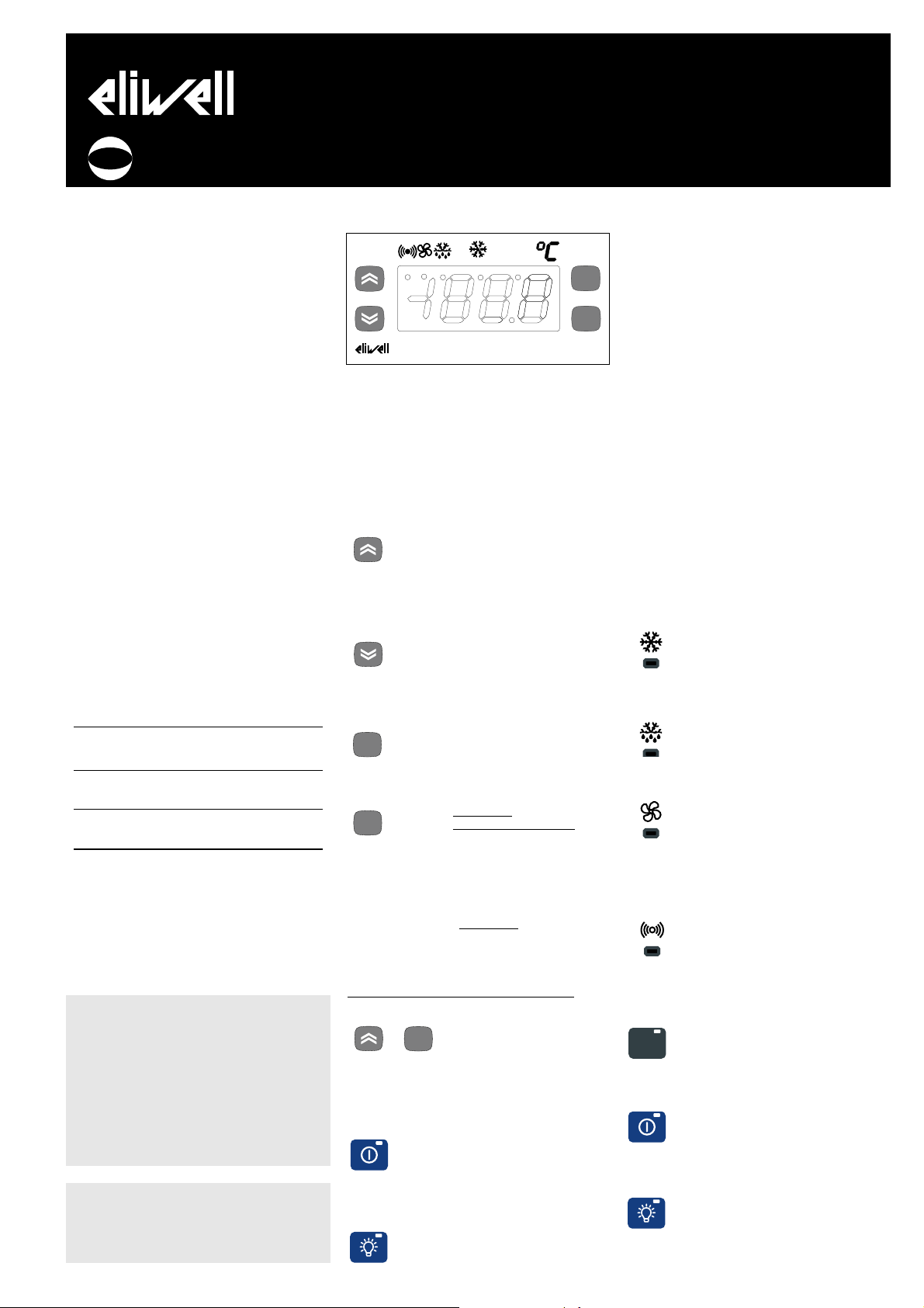
The user has a keyboard with a 6 LED
display and four buttons for controlling
status and programming of the instrument.
BUTTONS AND MENUS
UP Button
Scrolls through the menu items
Increases the values
Parameter programmable*
(see H31 parameter: by default
Manual DEFROST is defrost)
DOWN Button
Scrolls through the menu items
Decreases the values
Parameter programmable*
(see parameter H32, by default
aux relay is active)
ESC button
ESC function (exit)
Parameter programmable*
(see H33 parameter)
set button
(press once)
MACHINE STATUS MENU
•Accesses the set point
•Displays the alarms
(if active)
•Dispays Pb1,Pb2 and Pb3
(see)
(hold down)
•Accesses the programming
Menu Parameters
UP button +esc button pressed simultaneously
(press for 2 seconds)
•Keyboard locking/unlocking
FOR WIDE AND 6 BUTTON IWK KEYBOARDS
“secondary” or function buttons
“ON-OFF” (hold down, see par.H02)
(function 2)
Switches unit on/off
Parameter programmable*
(see H35 parameter)
“LIGHT” button (function 1)
Switches on the light
Parameter programmable*
(see H34 parameter)
*NOTE:
The “primary” buttons can be programmed using the parameters H31…H33
(see)
In standard configuration the buttons are
set by default as:
• “UP” button; par. H31=1; enables
manual defrosting
• “DOWN” button; par. H32=0 no related
function (disabled)
• “esc” button; par. H33=3 enables the
reduced set function
• “set” button; not programmable.
LEDS
“Display” LEDs
The display is red, the 6 LEDs are red
“eco” LED
•ON for parameter programming level 2;
•blinking when OSP reduced set is entered
Compressor LED
ON for compressor on;
•blinking for protection delay, or enabling
blocked.
Defrosting LED
ON when automatic defrosting in progress;
•blinking when manual defrosting is in
progress;
LED Fans
•ON when fan is on;
•blinking for manual or D.I. (Digital Input)
fan forcing
(%RH function, humidity reduction
if par. H11=13)
Alarms LED
•ON for active alarm;
•blinking for silenced alarm
FOR IWK WIDE AND 6-BUTTON LED
KEYBOARDS ONLY
“set” LED
•ON for paramter programming level 2;
•blinking when OSPreduced set is entered
“on-off” LED
ON when unit “off” (on STAND-BY);
•OFF when unit on;
“light” LED
ON when output is active, (%RH / light
depending on model and/or default set-
tings);
ON when output is also active from D.I.
IWP 740 (LX)
Electronic controllers for “ventilated” refrigerating units
Model
IWK keyboard
IWK std 6 buttons
IWK 32x74 4
buttons
IWK wide
6 (max 8) buttons
IWP power module
IWP 740 (LX)
Characteristics
open board keyboard
68x124mm (LxH)
Eliwell std. keyboard
32x74x60mm (LxHxD)
“IWC” style keyboard
180x37x45mm (LxHxD)
base module with 4 relays
92x121mm (LxH)
MODELS
COD. 9IS23033
REL. 3/04
I
PLEASE NOTE - WIDE AND 32X74 KEYBOARD ALL LEDS ARE RED
PLEASE NOTE - IF WIDE OR “OPEN”
KEYBOARDS ARE USED, SOME FUNCTIONS RELATED TO THE DEDICATED
BUTTONS MAY NOT BE AVAILABLE:
READ THE USER INTERFACE SECTION
ONLY FOR IWK WIDE AND 6-BUTTON
KEYBOARDS
“ AND TABLE OF PARAMETERS, “configuration parameters”
eco
f nc
set
aux
IWK
fnc
set
fnc
set

NOTE:: the LEDS are OFF in any other circumstances
not described here
START-UP
At Start-up the unit performs a Lamp
Test; the display and LEDs flash for a few
seconds/(888), to check that they are
working correctly.
IWK KEYBOARD LOCKING
Press the “UP” and “esc” buttons for 2
seconds to lock the keyboard. Repeat to
unlock. The keyboard can also be locked
with a parameter (par. LOC) NOTE: If the
keyboard is locked you can access the
Programming Menu by pressing the “set”
button.
The Set point can also be displayed.
ACTIVATING MANUAL DEFROST CYCLE
To activate the defrost cycle manually,
press the “UP/Def” button (if configured
=1) for 2 seconds.
If the conditions for defrosting are not
present (for example, the evaporator
probe temperature is higher than the
end of defrost temperature) or parameter OdO≠0, the display will flash three (3)
times to indicate that the operation will
not be performed.
ACCESSING AND USING MENUS
The instrument has two main menus: the
Machine Status menu and the
Programming menu.
The resources are arranged in a menu
that can be accessed:
• by pressing and quickly releasing the
“set” button ((Machine Status menu) or
• holding down the “set” button for
more than 5 seconds (Programming
menu) or
• holding down the “UP” and “DOWN”
buttons for more than 3 seconds (local
keyboard Programming menu). To access
the contents of each folder, indicated by
the relevant label, just press the “set”
button once.
You can now scroll through the contents
of each folder, modify it or use its functions. If you do not use the keyboard for
over 15 seconds (time-out) or if you
press the “fnc” button once, the last
value shown on the display is confirmed
and you return to the previous screen
mask.
MACHINE STATUS MENU
(See Machine Status Menu Diagram)
To access the Machine Status menu,
press the “set” button and quickly
release it If no alarms are present, the
label “SEt” appears.
By using the “UP” and “DOWN” buttons
you can scroll through the other folders
in the menu:
-AL: alarm folder (if alarms present,
except for faulty probes/probe errors;
-SEt: Setpoint setting folder;
-rtc: real time clock folder;
-Pb1: probe 1 value folder;
-Pb2: probe 2 value folder;
-Pb3: probe 3 value folder (if present);
Set Setting
Access the Machine Status menu, press
the “set” button and quickly release it
The “Set” folder label appears. To display
the Set point value, press the “set” button again.
The value appears on the display.
To change the Set point value, use the
“UP” and “DOWN” buttons within 15 seconds.
If the parameter is LOC = y the Set point
cannot be changed.
Real Time Clock
By pressing the “set” button when the
related “rtc” label appears, the label d00
(days) is displayed. Use the “UP” and
“DOWN” buttons to set days.
If you do not use the buttons for over 2
seconds or if you press “set” you switch
to the hours (h00) and minutes (‘00)
folders: use the “UP” and “DOWN” buttons to set the hours and minutes
respectively. If you do not use the keyboard for over 15 seconds (time-out) or
if you press the “fnc” button once you
are taken back to the previous screen
mask.
NOTE1: Always use the “set” button
to confirm the hours/minutes/days
setting.
NOTE2: We recommend considering
the first day d00 as SUNDAY.
Alarm on
If an alarm condition exists when the
Machine Status menu is accessed the
“AL” folder label appears (see section on
“Diagnostics”).
Displaying Probes
By pressing the “set” button when the
corresponding label appears, the value of
the probe associated with it is displayed.
PROGRAMMING MENU
(See Programming Menu Diagram)
1) Displaying level 1 parameters
To access the Programming menu, hold
the “set” button for more than 5 seconds. If specified, the level 1 access
PASSWORD will be requested (see parameter “PA1”) and (if the password is correct) the label of the first folder will
appear. If the password is incorrect, the
display will show the PA1 label again.
To scroll other folders, use “UP” and
“DOWN” buttons; the folders will only
display all the level 1 parameters.
NOTE: at this level level 2 parameters
are NOT visible, even if NOT password-protected.
2) Displaying level 2 parameters
Go into the “CnF” folder in the
Programming Menu, and scroll down the
parameters until you reach the PA2 label.
By pressing and releasing the “set” button you will enter the level 2 parameters
and the label of the first folder in the
programming menu will appear.
Level 2 parameters can be protected by a
second password (see “PA2” parameter in
“diS” folder, not to be confused with PA2
label in the “CnF” folder). If specified,
level 2 parameters are hidden to user;
when accessing the “CnF” folder the level
2 access PASSWORD will be requested
and (if the correct password is entered)
the label of the first folder in the programming menu will appear.
NOTE: At this level the folders will
only display all the level 2 parameters. Therefore level 1 parameters will
only be visible if you exit the
Programming Menu and repeat procedure 1).
To enter the folder, press “set”. The label
of the first visible parameter will appear.
To scroll through the other parameters,
use the “UP” and “DOWN” buttons; to
change the parameter, press and release
“set”, then set the desired value using
the “UP” and “DOWN” buttons and confirm with the “set” button. Move on to
the next parameter.
NOTE: It is strongly recommended that
the unit is switched off and on again
each time parameter configuration is
changed in order to prevent malfunctioning of the configuration and/or ongoing
timings.
LOCAL KEYBOARD PROGRAMMING
MENU
To access the Local Keyboard
Programming menu, press the “UP” and
“DOWN” buttons for 32x74 and wide
keyboards and the “UP” and “ESC” buttons for “open” keyboards for at least 3
seconds.
If specified, the access PASSWORD will be
requested (see parameter “PA3”) and (if
the password is correct) the PLO (Local
Parameters) label will appear. This
folder contains the local keyboard
parameters (see Local Keyboard
Parameters table).
If the password is incorrect, the display
will show the PA3 label again. NOTE: the
folder may NOT be visible; if this is
the case, local keyboard programming
cannot be accessed.
To enter the folder, press “set”. The label
of the first visible parameter will appear.
To scroll through the other parameters,
use the “UP” and “DOWN” buttons; to
change the parameter, press and release
“set”, then set the desired value using
the “UP” and “DOWN” buttons and confirm with the “set” button. Move on to
the next parameter.
PASSWORD 1) PROGRAMMING MENU
The passwords “PA1” and “PA2” allow
level 1 and level 2 parameters to be
IWP 740 (LX) 2/20

accessed. In the standard configuration
passwords are not present.
To enable them (value≠0) and assign
them the desired value, access the
Programming menu in the “diS” folder .
If passwords are enabled, they will be
requested:
- PA1 when entering the Programming
menu (see the “Programming Menu“ section);
- PA2 in the “Cnf” folder containing level
1 parameters.
2) LOCAL KEYBOARD
Password “PA3” gives access to the local
keyboard parameters. In the standard
configuration the password is not present. To enable it (value ≠0) and assign
it the desired value, access the Local
Keyboard Programming menu in the
“PLO” folder .
If passwords are enabled, they will be
requested:
- PA3 when entering the PLO menu
USING COPY CARD
The Copy Card is an accessory connected
to the TTL serial port that is used to program the unit parameters quickly (upload
and download parameter map to one or
more units of the same type). The operation is performed as follows:
Fr-Format (level 2 par.)
This command can be used to format the
copy card when used for the first time
or when used with models that are not
compatible.
Attention: when the copy card has been
programmed and the “Fr” parameter is
used all the data entered is cancelled.
This operation cannot be undone.
UL-Upload
This operation unloads the programming
parameters from the instrument.
dL-Download
This operation downloads the programming parameters to the instrument.
NOTE:
• UPLOAD: instrument —>Copy Card
• DOWNLOAD: Copy Card —> instrument
The operations are performed by accessing the folder identified by the “FPr”
label and selecting the “UL”, “dL” or “Fr”
commands; the operation is confirmed
by pressing the “set” button. If the operation is successful, a “y” is displayed
whereas if it fails an “n” will be displayed.
Download “from reset”
Connect the copy card with the instru
ment OFF. When the instrument is
switched on the programming parameters will be downloaded into the copy
card; when the lamp test has been completed, the display will show for about 5
seconds:
• label dLY if copy operation is successful
• label DLn if operation fails
NOTE:
• after downloading the instrument will
work with the new parameters map settings.
DISTANCE-MANAGED SYSTEMS
(LX MODELS ONL
Y)
Televis systems can be connected using
the RS 485 serial input (see connection
diagram for terminals on base 1-2-3)
In this case, use the Televis plug-in
module available as an optional extra
(TTL - RS 485 converter)
To configure the instrument to do this,
you need to access the folder(only in LX
models) identified by the “Add” label
and use the “dEA” and “FAA” parameters.
FUNCTIONS
LINK
The Link function is used to connect several IWP base units and IWK keyboards up
to a maximum of 10 instruments (1
Master base device and 4 slaves, 1 IWK
keyboard for the Master base and 4 IWK
Slave keyboards).
The serial connection between the devices
is implemented by way of an “powered”
serial connection (SHORT DISTANCE).
NOTE: for a SHORT DISTANCE connection two adjoining modules must be
less than 10 m apart whereas the two
furthest modules must be less than 50
m apart.
MASTER-SLAVE-ECHO DEFINITIONS
AND NETWORK COMMANDS
1)IWP base
•Master Base
Strumento che gestisce la rete, inviando i
comandi agli Slave. La selezione del
Master avviene tramite il parametro L00 (il
valore 0 definisce il Master).
The Master Base is the only default
device that is able to:
Activate for all the Slaves:
a) switching lights on/off;
b) alarm silencing;
c) activating auxiliary set point (reduced
set);
d) placing devices in STAND-BY (ON-OFF);
e) activating the auxiliary relay. The
Master also:
1) synchronizes the displays on all the
Slaves and Echos with its own display;
2) synchronizes defrosting (simultaneous
or sequential);
3) synchronizes the compressors (with a
delay in activating them, see par. don);
4) shares probe 1 (temperature probe) so
that there is only one thermostat control:
if this is the case, the Master probe is used
by all the Slaves for regulation.
•Slave Base
Instrument(s) supplied with own controls
which also perform(s) commands issued
by the Master (with parameters L00..L09).
The Slave Base according to parameter
L08 is also enabled for:
a) switching lights on/off;
b) placing devices in STAND-BY (ONOFF).
According to parameters L00..L09 it may
also become dependent on/independent
of the Master with regard to points a)-b)
with regard to defrosting management
and thermostat control probe sharing. By
using parameter L09, the slave decides
whether to use the probe shared by the
Master or its own to adjust temperature.
In the first case, the probe can be omitted
on the Slave.
2) IWK keyboard
•Master keyboard
Keyboard connected to the network that
configures and displays the status of the
Master base unit. Each keyboard can be
configured to control the Master or Slave
base units.
•Slavekeyboard
Keyboard connected to the network that
configures and displays the status of the
Slave base unit. Each keyboard can be
configured to control the Master or Slave
base units. (using parameters L00..L09).
• Echo keyboard
Keyboard connected to the network that
only displays the values of the instrument
which it is associated to (it does not therefore have with its own I/O resources, but
only acts as a repeater).
NOTE: several Echo keyboards can be
connected to the same Master or Slave
base unit.
LINK Network Defrosting
The main characteristics of the Link network is the control of defrosting; the
Master sends the defrost command which
can be performed synchronously(1) or
sequentially (2) (defrost after defrost),
without affecting the normal protections
or delays of each instrument (see parameter L03).
(1) Synchronized defrost
The synchronization of defrosting is
effected with regard to the actual
defrosting phase; dripping and all the
functions that follow the defrosting stage
are therefore not considered. The Master
only supplies the commands that enable
the start of defrosting or thermostat control without interfering with the normal
protections or delays on each device.
When the slave units are awaiting thermostat control enabling from the Master
(when synchronized defrosting has terminated) the defrost LED blinks.
WARNING: if the Slaves connected to the
network are programmed to accept the
commands from the Master concerning
defrosting and network functions, no
defrosting or functions associated with
the events requested by the Slaves will
be enabled.
Only in the event of a “no link” (error
E7), the Slaves will activate defrosting
and functions associated with the events
requested by the Slaves.
IWP 740 (LX) 3/20

(2) Sequential Defrosting
The Master enables defrosting for the
various devices in the network. When
each device has completed defrosting
(and not dripping) it begins thermostating.
Finally, using the parameters dty, defrost
type. (and and dCt, defrost
Countingtype thedefrosting modes are
defined.
LIGHT-DOOR SWITCH
• button enabled
If you press the “LIGHT” button the auxiliary relay/light is activated (if it was off,
otherwise if it was on it is deactivated
(see par. H34, for IWK WIDE and 6-button keyboards only ).
• digital input enabled
The digital input can be configured as
auxiliary/light (parameter H11=3/4): in
this case, a digital output can be configured as light/AUX (parameters
H21…24=5).
As stated, this function can be used to
activate the light relay if it was de-energized or energize it if this was not the
case.
When the digital input (D.I.) is activated
the light relay is enabled (if par. dSd=y)
and the light relay is disabled when the
D.I. is disabled.
The status is stored so that it functions
correctly in the event of a black-out; the
light button and the light enable function
can also be activated is the unit is in
STAND-BY (see par. H06). The light but-
ton always disables the light relay if par.
OFL=y
STAND BY/ON-OFF
Note: The STAND BY/ON-OFF function
can be rapidly selected by pressing
the dedicated on/off button for at
least 2 seconds.
Once the STAND-BY/ON-OFF function
has been enabled, the display goes out,
the controls are blocked including the
alarms and the cycle times are reset.
OFF will also be displayed.
The status is stored so that when power
is restored after a black-out the device
can resume operation in the same way as
before the power failure. After start-up,
the temperature alarm is excluded for
the period of time set by parameter PAO.
%%RRHH FFUUNNCCTTIIOONN
Press one of the programmable buttons
to activate the %RH function (enabling
the humidity reduction control) if the
parameter H31…33=9 has been set.
The %RH function can also be D.I.enabled if par. H11=9.
If this control is enabled, the fans operate continuously (always on). During
defrosting the fans are controlled by the
defrosting parameters and during the
dripping cycle they will be turned off
even if RH% is active.
NOTE: RH% status has priority over all
other parameters.
If there is a power failure or the machine
has been turned off, the RH% status will
be restored as soon as the mains power
supply returns or the machine is turned
on.
NIGHT & DAY CONTROL
The Night & Day control algorithm can
be used to set events and cycles at predefined times of the week. You can set
an event start time and duration, as well
as functions and defrostings (daily or festive) to be enabled for each day of the
week. By pressing the “set” button when
the “nad” label appears, the label d0 (day
1) is displayed in the “Programming”
menu. Tip: consider d0 = Sunday). Use
the “UP” and “DOWN” buttons to set
other days (d1 (day 2 = Monday)…d6
(day 7 = Saturday)) and Every Day. By
pressing “set” the first parameter E00 is
displayed; use the “UP” and “DOWN”
buttons to scroll through other parameters E01…03.
If you do not use the keyboard for over
15 seconds (time-out), or if you press the
“fnc” button once, the last value shown
on the display is confirmed and you
return to the previous screen mask.
The different functions are set using the
appropriate parameters (see the parameter table for the folder with the “nad”
label)
GENERAL PRESSURE SWITCH CONTROL
The Pressure switch algorithm can be
used to effect a diagnostic role on a digital input (see par. H11-H14 =11).
Every time the pressure switch is triggered, the compressor is deactivated, the
alarm LED is turned on and the displayed
in the alarm folder of a subfolder called
nPA. The number of times the pressure
switch has been activated is stored in this
folder: once the number set by the parameter PEn has been reached this folder is
replaced by the PA (pressure alarm)
Label. When the pressure switch input is
reset, control restarts automatically and
any timings and protections are
observed.
If the number of activations in the interval established by parameter PEI (pressure switch error count interval) exceeds
the number established by parameter
PEn (number of errors allowed per pressure switch input) the control activates
an alarm condition. This condition consists in 1. Deactivation of the compressor
outputs, fans and defrosting;
2. Display of the PA label in the alarm
folder;
3. Switching on of the alarm LED and
alarm relay if configured.
Once the device is in alarm mode, it
must be switched off and on again or
reset using the rAP (pressure switch
alarm reset) in the Fnc functions menu
(see).
During the pressure switch intervention
time, counting of the defrosting time
proceeds normally.
If parameter PEn = 0 the function is
excluded, the alarms are excluded and
the counts deleted and disabled.
MAXIMUM AND MINIMUM PRESSURE
SWITCH CONTROL
As above with the digital input set correctly (see par. H11-H14 =9, Minimum
pressure switch input; H11-H14 =10,
Maximum pressure switch input). In this
case the labels displayed will be LPA
(minimum) or HPA (maximum).
PREHEATING CONTROL (THERMAL
PROTECTION)
As above with the digital input set correctly (see par. H11-H14 =12). In this case
the label displayed in the Alarm folder
will be Prr and the compressor LED will
blink.
DIAGNOSTICS
The alarm condition is always signalled
by a buzzer (if present) and the alarm
icon LED. The alarm signals from the
faulty thermostat control probe (probe
1), the faulty evaporator probe (probe 2),
and the faulty display probe (probe 3)
appear on the instrument display as E1,
E2, and E3 respectively.
An error condition in probe 1 (thermostat control) causes the following:
• E1 code appears on display
• compressor is activated as indicated by
“Ont” and “Oft” parameters if these are
programmed for duty cycle or:
The error condition for probe 2 (evaporator) causes the following:
• E2 code appears on display
• end of defrost caused by time-out. The
error condition for probe 3 (display)
causes the following:
• E3 code appears on display. Other
IWP 740 (LX) 4/20
DISPLAY
E1 E2
E3
If simultaneous, they will be showed on the display
alternatively every 2 seconds
If E1 or E2 appears on the Master (see LINK network) and the display is shared, the slaves will
always show the Master display: to understand
which unit is faulty, refer to the alarm LED for
each instrument.
FAULT
Faulty probe 1 (thermostat control)
Faulty probe 2 (evaporator) Faulty
probe 3 (display)
Probe errors table
Ont
0
0
>0
>0
Oft
0
>0
0
>0
Compressor output
OFF
OFF
ON
dc
alarms do not appear on the instrument
display but can be seen in the “Machine
Status” menu in the “AL” folder.
Regulation of the maximum and minimum temperature alarm refers to the
thermostat control probe (probe 1)
and/or display probe (probe 3). The temperature limits are defined by the “HAL”
(maximum alarm), “LAL” (minimum
alarm) and PbA (alarm configuration on
probe 1,3 or both) parameters.
MAXIMUM AND MINIMUM TEMPERATURE ALARM
In an alarm condition occurs and alarm
exclusion times are not in progress (see,
alarm exclusion parameters), the fixed
alarm icon is turned on and the relay
configured as an alarm is activated. This
kind of alarm does not affect the regulation in progress. Alarms are considered
as absolute (default) values or as values
related to the Set point (the distance
from the Set point itself) and based on
the Att parameter. This alarm condition
can be viewed in the folder “AL” with the
labels “AH1-AL1”.
ALARM WITH THRESHOLD (PROBE 3)
By setting the PbA=3 parameter an alarm
is associated to probe 3. It refers to a
specific threshold (defined by the SA3
parameter). An over-temperature or an
under-temperature alarm is generated
and the icon is turned on. This alarm
condition can be viewed in the “AL” folder with the labels “AH3-AL3”.
The alarm is managed as a temperature
alarm referred to probe 3: refer to standard delays and backswings
DEFROST ALARM
If defrost ends because of a time-out
(rather then because a defrost end temperature is detected by the defrosting
probe), an alarm is generated and the
icon (if dAt=y) is turned on.
This condition can be viewed in the “AL”
folder with the label “Ad2”. Automatic
back swing occurs when the next defrost
starts. By pressing any button during the
alarm condition, the signal light disappears. In order to cancel the alarm properly, you must wait until the next defrost.
EXTERNAL ALARM
The device can also control an external
alarm, i.e. from a digital input. If the digital input is enabled, the alarm control is
activated by programming and remains
enabled until the next time the digital
input is deactivated. The alarm is signalled by turning on the fixed alarm icon,
activating the relay configured as alarm
and deactivating compressor, defrost and
fan controls (if specified by the “EAL”
parameter). This alarm condition can be
viewed in the “AL” folder with the label
“EA”. The relay can be silenced; even if
the alarm icon starts blinking, controls
stay locked until the next time the digital
input is deactivated.
OPEN DOOR ALARM
If a door is open, in response to a delay
defined by the tdO parameter the Open
Door alarm is signalled. The alarm is signalled by the alarm icon that starts blinking. This alarm condition can be viewed
in the “AL” folder with the label “Opd”.
LINK NETWORK ALARM
In the event of a master/slave/echo communication failure, the NO LINK alarm is
signalled. This alarm condition can be
viewed in the “AL” folder with the label
“E7”.
NOTE:
•The E7 error is signalled after approx.
20 seconds in “no link” condition to
avoid any link disturbance causing communication errors.
•The E7 error is also signalled for
addressing conflicts when: a) the number
of Slaves set on the MASTER is different
from the effective number of Slaves on
the network b) 2 or more Slaves have the
same address.
PRESSURE SWITCH ALARM
If the pressure switch alarm is activated
by the general pressure switch control,
the label “PA” will appear in the “AL”
folder. The device must be switched off
and then on again (machine reset) or the
alarms reset in the alarm folder. If the
pressure switch alarm is activated by the
minimum (maximum) pressure switch
control, the label “LPA” (“HPA”) will
appear in the “AL” folder. Once in alarm
mode, the device must be switched off
and then on again (machine reset) or the
alarms reset in the alarm folder.
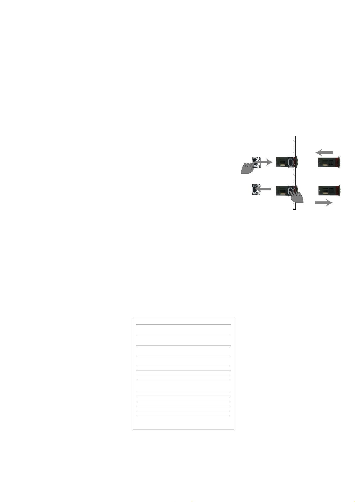
MECHANICAL ASSEMBLY
The unit has been designed for:
• 32x74 4 button IWK keyboard: panel
mounted. Drill a 29x71 mm hole, insert
the unit and fix it in place using the
brackets supplied.
•IWK wide keyboard: panel mounted.
Drill a 150x31 mm hole , insert the unit
and fix it on the front using the special
screws supplied.
• 6 button IWK keyboard: open board
• IWP power module, open board
92x121mm for open installation. Do not
assemble the keyboard in excessively
dirty and/or dirty locations because it is
designed to be used in locations with
normal degrees of pollution. Always
make sure that the area next to the unit
cooling slits is adequately ventilated.
IWP 740 (LX) 5/20
DISPLAY
AH1
AL1
AH3
AL3
Ad2
EA
Opd
E7
E10
PA
LPA
HPA
Press any button to silence the alarm. In this case
the LED will start to blink.
ALARM
High temperature alarm (referring to
thermostat control probe or probe 1)
Low temperature alarm (referring to
thermostat control probe or probe 1)
High temperature alarm (referring to
probe 3)
Low temperature alarm (referring to
probe 3)
End of defrost due to time-out
External alarm
Open Door Alarm Master-Slave
Communication failed
Clock battery alarm
General pressure switch alarm
Minimum pressure switch alarm
Maximum pressure switch alarm
Alarm table

CONNEXIONS
ELECTRICAL
Attention! Always switch off machine
before working on electrical connections.
The unit is fitted with:
• IWP power base: FASTON connectors
and screw connectors for connecting
electrical cables with diameter of 2,5
mm
2
(only one conductor per terminal for
power connections) for terminal capacity,
see the label on the instrument.
The relay contacts are voltage free. Do
not exceed the maximum current
allowed. For higher loads, use an appropriate contactor. Make sure that the
power voltage complies with the device
voltage. Probes have no connection
polarity and can be extended using a regular bipolar cable (note that if probes
are extended this affects the EMC electromagnetic compatibility of the instrument: wiring operations must be performed very carefully). Probe cables,
power supply cables and the TTL serial
cables should be kept separate from
power cables.
• 4 button IWK standard or wide key-
board: screw connectors** (or quick disconnect connectors) for connection of
electrical cables;
**with max. diameter of 2 mm
2
:: for terminal capacity, see the label on the
instrument.
CONDITIONS OF USE
PERMITTED USE
For safety reasons the instrument must
be installed and used according to the
instructions provided. In normal operating conditions, parts with dangerous voltage levels must not be accessible. The
device must be adequately protected
from water and dust as per the application and must also only be accessible by
using tools (with the exception of the
front panel). The device is ideally suited
for use on household appliances and/or
similar refrigeration equipment and has
been tested with regard to the aspects
concerning European reference standards
on safety. It is classified as follows:
• according to its manufacture: as an
automatic electronic control device to be
independently mounted;
• according to its automatic operating
features: as a 1 B-type operated control
type;
• as a Class A device in relation to the
category and structure of the software.
UNPERMITTED USE
The use of the unit for applications other
than those described is forbidden. It
should be noted that the relay contacts
supplied with the device are functional
and therefore exposed to potential
faults. Any protection devices required to
comply with product requirements or
dictated by common sense due to obvious safety reasons should be installed
externally.
IWP 740 (LX) BASE
TECHNICAL DATA
Casing: open board. Dimensions:
•IWP 740 (LX) model 92x121 mm.
Usage temperature: -5…55 °C. Storage
temperature: -30…85 °C. Usage ambient
humidity: 10…90 % RH (non-condensing).
Storage ambient humidity: 10…90% RH
(non-condensing).
Display range: 50…110 (NTC); -55…140
(PTC) °C without decimal point (parameter selectable), on display 3 digits + sign.
Analogue inputs: three NTC inputs
(PTC preset in factory on request) Digital
inputs: 1 voltage-free (clean contact)
parameter configurable digital input.
Serial outputs (see also Serial Output
table):
TTL Serial Outputs (standard 5-way con
-
nectors):
• TTL for Copy Card connection.
485 serial output for connection to the
Televis system (LX MODELS ONLY):
• 485 serial for connection to the
TelevisSystem. Televis systems can be
connected using the RS 485 serial input
(see connection diagram for terminals on
base 1-2-3)
Note: in this case, use the Televis
plug-in module available as an optional extra (TTL - RS 485 converter)
Serial Outputs for base board-keyboard
connections:
• “powered” serial connection (also
called SHORT DISTANCE) through +12V
lines (only for base board-keyboard connections), GND and DATA terminals for:
a) simple connection between base
board and keyboard*;
b) multiple connection between several
modules on the network (up to a max. of
5 modules)**
Note:
1) the modules can be base boards or
keyboards.
2) two adjoining modules must be less
than 10 m apart whereas the two furthest modules must be less than 50 m
apart.
3) *in this case an optional plug-in
module (vertical) is necessary for the
base board
Digital outputs: 4 outputs on relays:
configurable:
•first output (A) 16A SPST 1 Hp 250Va,
(12 A SPST 1 Hp 250Vaon request);
• second output (B) 16 A SPST 1 Hp
250Va;
• third output SPST (C) 8A SPST 1/2 Hp
250Va;
• fourth output (D) 8(3)A SPDT 1/2 Hp
250Va
Measurement range: from -55a 140 °C.
Accuracy: better than 0.5% of bottom
scale +1 digit.
Resolution: 1 or 0.1 °C.
Consumption: 6 VA.
Power supply: 230 Va/c ±10% 50/60 Hz
Attention: check the power supply specified on the instrument label; for any
information on relay capacity and power
supplies contact the Sales Office).
STANDARD 4 BUTTON
IWK KEYBOARD
TECHNICAL DATA
Front protection: IP65.
Casing: plastic body in resin type PC+ABS
UL94 V-0, inspection window in polycarbonate, buttons in thermoplastic resin.
Dimensions: front 74x32 mm, 30 mm
depth.
Mounting: on panel, with drilling template 71x29 mm (+0.2/—0.1 mm).
Usage temperature: -5…55 °C.
Storage temperature: -30…85 °C.
Usage ambient humidity: 10…90 % RH
(non-condensing).
Storage ambient humidity: 10…90% RH
(non-condensing).
Display range: 50…110 (NTC); 55…140
(PTC) °C without decimal point (parameter selectable), on display 3 digits + sign.
Measurement range: from -55a 140 °C.
Accuracy: better than 0.5% of bottom
scale +1 digit.
Resolution: 1 or 0.1 °C.
Serial Outputs: see IWP740 (LX)
Technical Data
Consumption: see IWP740 (LX)
Technical Data
Power supply: from IWP power module.
IWP 740 (LX) 6/20
 Loading...