

Page 1
USER INTERFACE
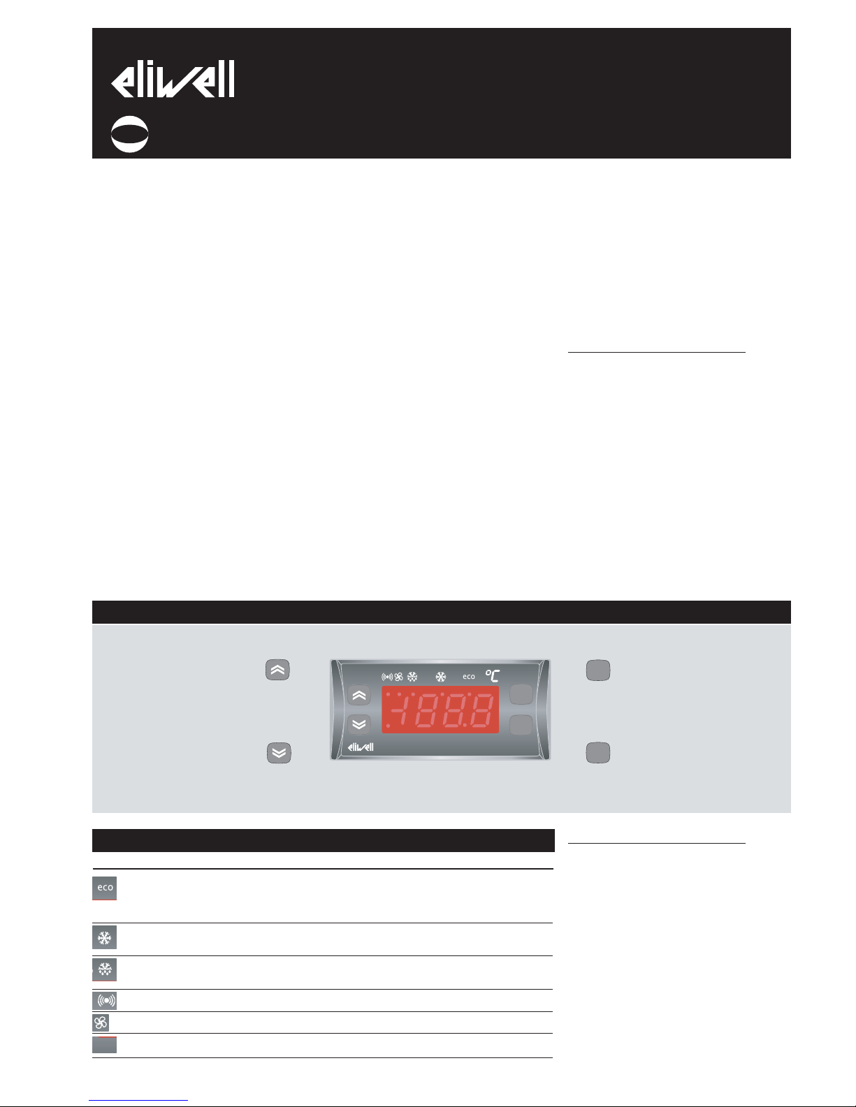
The user has a display and four buttons
for controlling instrument status and programming.
At start-up the instrument performs a
Lamp Test; the display and LEDs flash for a
few seconds to check that they are working correctly. The instrument has two main
menus: the Machine Status menu and the
Programming menu.
ACCESSING AND USING MENUS
The resources are arranged in a menu that
can be accessed by pressing and quickly
releasing the “set” button (Machine Status
menu) or holding down the “set” button
for more than 5 seconds (Programming
menu). To access the contents of each
folder indicated by the relevant label, just
press the “set” button once.
You can now scroll through the contents
of each folder, modify it or use its functions.
If you do not use the keyboard for over 15
seconds (time-out) or if you press the
“fnc” button once, the last value shown on
the display is confirmed and you are taken
back to the previous screen mask.
MACHINE STATUS MENU
(See Machine Status Menu Diagram)
To access the Machine Status menu, press
the “set” button and quickly release it.
If no alarms are present, the label “SEt”
appears. By using the “UP” and “DOWN”
buttons you can scroll through the other
folders in the menu:
-AL: alarm folder (if alarms present, except
for faulty probes/probe errors and COH);
-SEt: Set point setting folder.
-Pb1: probe 1 value folder;
-Pb2: probe 2 value folder;
-Pb3: probe 3 value folder (if present);
Set setting
Access the “Machine Status” menu, press
the “set” button and quickly release it. The
“Set” folder label appears. To display the
Set point value, press the “set” button
again.
The Set point value appears on the display.
To change the Set point value, use the
“UP” and “DOWN” buttons within 15 seconds. If the parameter is LOC = y the Set
point cannot be changed.
Alarm on
If an alarm condition exists when the
Machine Status menu is accessed the “AL”
folder label appears (see section on
“Diagnostics”).
NOTE: Always use the “set” button to
confirm the hours/minutes/days setting.
NOTE2: We recommend considering the
first day d00 as SUNDAY.
PROGRAMMING MENU
(See Programming Menu Diagram)
1) Displaying level 1 parameters
To access the Programming menu, hold
the “set” button for more than 5 seconds.
If specified, the level 1 access PASSWORD
will be requested (see parameter “PA1”)
and (if the password is correct) the label
of the first folder will appear. If the password is incorrect, the display will show the
PA1 label again.
When the instrument is on stand-by, parameter programming can be accessed with
the display both on and off.
Use the “UP” and “DOWN” buttons to
scroll through the other folders; the fold-
ers will only display level 1 parameters.
NOTE: at this point level 2 parameters
are NOT visible even if NOT passwordprotected.
2) Displaying level 2 parameters
Go to the “CnF” folder in the
Programming Menu and scroll down the
parameters until you reach the PA2 label.
By pressing and releasing the “set” button
you will enter the level 2 parameters and
the label of the first folder in the programming menu will appear.
Level 2 parameters can be protected by a
second password (see “PA2” parameter in
“diS” folder, not to be confused with PA2
label in the “CnF” folder). If specified, level
2 parameters are hidden from the user;
when accessing the “CnF” folder the level
2 access PASSWORD will be requested and
(if the correct password is entered) the
Position Associated function Status
Set point/Reduced set point ON for parameter programming level 2
blinking when reduced set point is entered
(set point ON for setting set point)
Compressor or relay 1 ON for compressor on; blinking
for protection delay or enabling blocked
Defrosting ON when defrosting in progress; blinking when activated
manually or by digital input
Alarm ON for active alarm; blinking for silenced alarm
Fans ON when fan is on
aux ON when auxiliary output is operating
ID 985
electronic controllers for “ventilated” refrigeration units
fnc
set
ID985
aux
set
fnc
cod. 9IS44048
rel. 4/06
GB
aux
UP button
Scrolls through the menu items
Increases values
Activates manual defrosting
(see H31 parameter)
DOWN button
Scrolls through the menu items
Decreases the values
Parameter programmable
(see H32 parameter)
fnc button
ESC function (quit)
Parameter programmable
(see H33 parameter
Set button
Accesses Set point
Accesses the Menus
Confirms the commands
Displays the alarms (if active)
Stores hours/min
LEDs
BUTTONS AND DISPLAY
Page 2

label of the first folder in the programming menu will appear.
NOTE: At this point the folders will
only display all the level 2 parameters.
Therefore level 1 parameters will only be
visible if you quit the Programming Menu
and repeat procedure 1).
To enter the folder, press “set”. The label
of the first visible parameter will appear.
To scroll through the other parameters,
use the “UP” and “DOWN” buttons. To
change the parameter, press and release
“set”, then set the desired value using the
“UP” and “DOWN” buttons and confirm
with the “set” button. Move on to the next
parameter.
NOTE: We strongly recommend that you
switch the instrument off and on again
each time parameter configuration is
changed in order to prevent malfunctioning of the configuration and/or ongoing
timings.
PASSWORD
Passwords “PA1” and “PA2” allow level 1
and level 2 parameters to be accessed.
There are no passwords in the standard
configuration. To enable them (value ≠0)
and assign them the desired value, access
the Programming menu in the “diS” folder.
If passwords are enabled, they will be
requested:
- PA1 when entering the Programming
menu (see the “Programming Menu“ section);
- PA2 in the “Cnf” folder containing the
level 1 parameters.
FnC FUNCTION FOLDER
The FnC folder (last folder visible from
the Programming Menu, level 1) contains the following functions.
They are activated using the “set” button
If the unit is switched off, the function
labels go back to their default status.
ACTIVATING MANUAL DEFROST CYCLE
To activate the defrost cycle manually,
press the “UP” button (if configured =1)
for 5 seconds. If the right defrosting conditions are not present (the temperature
of the evaporator probe is higher than the
end of defrost temperature, for example)
or parameter OdO≠0, the display will flash
three (3) times to indicate that the operation will not be performed.
USING THE COPY CARD
The Copy Card is an accessory connected
to the TTL serial port and used for quick
programming of the unit parameters
(upload and download parameter map to
one or more units of the same type).
Operations are described below:
Fr-Format (level 2 parameter)
This command can be used to format the
copy card necessary when used for the
first time or when used with models that
are not compatible. Warning: when the
copy card has been programmed all the
data entered is cancelled when the “Fr”
parameter is used. This operation cannot
be undone.
UL-Upload
This operation uploads the programming
parameters from the instrument.
dL-Download
This operation downloads the programming parameters to the instrument.
NOTE:
• UPLOAD: instrument —> Copy Card
• DOWNLOAD: Copy Card —> instr.
The operations are performed by accessing
the folder identified by the “FPr” label and
selecting the “UL”, “dL” or “Fr” commands.
The operation is confirmed by pressing the
“set” button.
If the operation is successful, a “y” is displayed whereas if it is unsuccessful an “n”
will be displayed.
Download “from reset”
Connect the Copycard with the instrument
OFF
When the instrument is switched on the
programming parameters will be downloaded; when the lamp test has been completed, the following appear on the display
for about 5 seconds:
• label dLY if copy operation is successful
• label DLn if operation fails
NOTE: after downloading the instrument
will work with the parameter map settings
that have just been downloaded.
KEYBOARD LOCKED
Keyboard operating can be locked by programming the “Loc” parameter (see folder
with “diS” table). If the keyboard is locked
you can access the Programming Menu by
pressing the “set” button.
The Set point can also be displayed.
ADVANCED FUNCTIONS
DOOR SWITCH INPUT
This is a clean contact digital input with
programmable polarity. The door switch
input functions are controlled by the values of the following parameters:
If activation state forcing is enabled (dOA
is not 0), the compressor and/or fan outputs can be activated when the time set in
parameters dCO and dFO expires.
Parameter H11 is used to configure the
digital input with values between -9 and
+9. Positive and negative values are used
to select the polarity assigned to the input
and:
NOTE:
the sign “-” indicates that the input is
activated when the contact is closed
The ‘+’ sign indicates that the input is
activated when the contact is open
DEVICE STAND-BY CONTROLLER
This controls the operating mode of the
device when it is on stand by according to
the following parameters:
The Stand-by controller can be digital input
or button enabled if suitably configured.
The status of the instrument when on
stand-by is determined by the value of
parameter H08. Three possible operating
modes are defined:
EXAMPLE 1: the display is off and the controllers active, the instrument signals any
alarms by reactivating the display - OFF DISPLAY
EXAMPLE 2: the display is off and all the
controllers, including the alarms, are also
disabled - STAND-BY
EXAMPLE 3: the display shows the “OFF”
label and all the controllers, including the
alarms, are also disabled- STAND-BY
DEFROST CONTROL
The instrument can be used to select different types of defrosting with the parameter dty, defrost type.
(defrost execution mode).
The dty parameter can have these values:
0 = electrical defrosting; the compressor is
turned off.
1 = cycle reversing defrosting (hot gas);
the compressor continues operating.
2 = Free mode defrosting (compressor dis
abled).
Configuration of 3
rd
probe as 2nd evap-
orator probe
The 3
a
probe can be used to control the
defrosting of a second evaporator by configuring a relay output as a 2nd evaporator
defrost relay (see par. H21…H26).
To implement this function:
a) configure the 3
rd
probe in 2nd evaporator defrost control mode (par. H43=2EP).
b) configure a relay output as 2nd evaporator defrost relay (configuration parameters H21…H26).
c) define the defrost mode by setting
parameter H45.
Start of defrosting
If two evaporators are used, defrosting
starts in three different ways that are
ID 985 2/10
Function
Reduced set point
Aux
Pressure switch alarm reset
**default
Function Label
NOT ATTIVA
SP**
AoF
rAP
Label
function
ACTIVE
OSP
Aon
rAP
Par Description
dOd Digital input switches off loads
dAd D.I. activation delay
OAO Alarm signal delay after disabling the digi-
tal input (door closed)
tdO Time out door open. Time out signalled
when D.I is activated.
(door open)
dOA Forced behaviour from
digital input
PEA Enables forced behaviour from door
switch and/or external alarm
dCO Delay in enabling compressor with
consensus
dFO Delay in enabling fans with
consensus
H11 Digital output configurability/polarity 1
H21...H25 Digital output configurability 1...5
Par Description
PAO alarm exclusion at start-up
OdO Output delay from power-on
H08 Operating mode in stand-by.
Page 3

determined by parameter H45.
• H45=0: Defrosting is enabled by controlling the temperature of the 1st evaporator so it is lower than parameter dSt,
•H45=1: Defrosting is enabled by controlling so that at least one of the two probes
is below its end of defrosting temperature
(dSt for the 1st evaporator and dS2 for
the 2nd evaporator)
• H45=2: Defrosting is enabled by controlling so that both the probes are below
their respective end of defrosting set
points (dSt for the 1st evaporator and dS2
for the 2nd evaporator)
The probe error condition is considered
the defrost calling probe.
When defrosting is terminated by a probe
or is timed out (see par. dEt), dripping follows (see par. dt).
End of defrosting
If two evaporators are used, defrosting
ends when both the probes have reached
or exceeded their respective end of
defrosting set points (dSt for the 1st evaporator and dS2 for the 2nd evaporator)
If one or both the probes are faulty,
defrosting is ended by a time-out.
NOTE:
• If there are no conditions for defrosting,
the request is ignored.
Defrosting of a single evaporator ends
when the value read by the respective
probe is equal to or higher than the end
of defrosting temperature or a time-out
occurs. Dripping starts when both defrosts
have been completed.
• If one or both the probes are faulty,
defrosting in the corresponding evaporator
is ended by a time-out.
The start of defrosting is permitted when the
corresponding temperature is lower than the
corresponding set point (dSt or dS2).
• If probe 3 is not configured as a probe
on the second evaporator (H43≠2),
defrosting on the second evaporator
occurs if a digital output is configured to
control defrosting on the second evaporator (see par. H21..H25). If this is the case,
defrosting is confirmed (as if ST3<dS2)
and ends with a time-out. The fan controller remains unchanged.
GENERAL PRESSURE SWITCH INPUT
CONTROLLER
This controller performs diagnostics on an
associated digital input using a configuration table. It is activated by setting parameters H11 and H12 = 9.
If the pressure switch input trips, the compressor loads are immediately deactivated,
the alarm LED lights up to signal tripping
and the label nPA in the alarm folder
appears on the display.
Controlling is performed using 2 parameters PEn and PEI:
nPA is a subfolder of AL (Alarms), and
keeps a record of each time the pressure
switch is activated if the value indicated by
PEn is reached in a period of time that is
less than or equal to PEI, the label nPA is
replaced by PA (pressure alarm).
The alarm conditions only occurs when the
maximum number of alarms is reached
before the time indicated by parameter
PEI expires. As soon as the first alarm
occurs, the time PEI is calculated.
If the number of times the pressure switch
is activated exceeds the number established PEn in the period PEI:
- compressor outputs, fans and defrosting
are deactivated
- the label PA is displayed in the folder AL
- the alarm LEDs and alarm relay if configured are switched on.
NOTE: Once the device is in alarm mode,
it must be switched off and on again or
reset by activating the rAP parameter in
the functions menu. The nPA folders can
be reset using the rPA function in the Fnc
folder.
NOTE: If parameter PEn is set to 0 the
function is excluded and the alarms and
counts are disabled.
CONDENSER FAN CONTROLLER
This controller is associated with probe
Pb3 and features:
- operating set point
- operating differential
- exclusion of fans in defrosting mode
- start-up delay after end of defrosting If a
digital output is set as condenser fans
(H21...H24=10) the output will behave as
shown below:
If probe Pb3 is not present and alarm E3 is
active, the controller will always be on
during the defrost cycle.
Probe 3 can be excluded and the failed
connection with the instrument will not
trigger an error message.
NOTE: During dripping time the output is
OFF.
NOTE: If a digital output is programmed
as condenser fans (H21...H25 =10) parameter SA3 is always an absolute value irrespective of the value of parameter Att.
DIAGNOSTICS
The alarm condition is always signalled by
a buzzer (if present) and the alarm icon
LED. The alarms from the faulty thermostat control probe (probe 1), the faulty
evaporator probe (probe 2), and the faulty
display probe (probe 3) appear directly on
the instrument display as E1, E2, and E3
respectively.
An error condition in probe 1 (thermostat
control) causes the following:
• E1 code appears on display
• compressor is activated as indicated by
“Ont” and “Oft” parameters if these are
programmed for duty cycle or:
The error condition for probe 2 (evaporator) causes the following:
• E2 code appears on display
• end of defrost due to time-out.
The error condition for probe 3 (display)
causes the following:
• E3 code appears on display Other alarms
do not appear on the instrument display
but can be seen in the “Machine Status”
menu in the “AL” folder.
The maximum and minimum temperature
alarm is regulated according to the thermostat control probe (probe1) and/or display probe (probe 3). The temperature
limits are defined by the “HAL” (maximum
alarm), “LAL” (minimum alarm) and PbA
(alarm configuration on probe 1,3 or both)
parameters.
MAXIMUM AND MINIMUM TEMPERATURE ALARM
If an alarm condition occurs and alarm
exclusion times are not in progress (see
alarm exclusion parameters), the alarm
icon lights up permanently and the relay
that is configured as an alarm is activated.
This type of alarm does not affect the regulating in progress.
Alarms are considered as absolute
(default) values or as values related to the
Set point (the distance from the Set point
itself) and based on the Att parameter.
If the alarms are relative (Att=1), the parameter HA1 is set to positive values and
LA1 to negative values.
This alarm condition can be viewed in the
folder “AL” with labels “AH1-AL1”.
ALARM WITH THRESHOLD (PROBE 3)
By setting the PbA=3 parameter an alarm
is associated to probe 3. It refers to a specific threshold (defined by the SA3 parameter). An over-temperature or an undertemperature alarm is generated and the
icon is turned on. This alarm condition can
be viewed in the “AL” folder with the
labels “AH3-AL3”.
When you set parameter PbA=4, probe 3
ID 985 3/10
Par. Description
PEn number of errors allowed per maximum/
minimum pressure switch input switch
input (number)
PEI Minimum/maximum pressure switch error
count time (minutes)
Output Value Pb3 Value
ON
≥ SCF OFF
≤ SCF - dCF
DISPLAY
E1
E2
E3
If simultaneous, they will be showed on the display
alternately every 2 seconds
FAULT
Faulty probe 1 (thermostat control)
Faulty probe 2 (1st evaporator)
Faulty probe 3 (display or 2nd evaporator)
Table of faulty probes
Ont
0
0
>0
>0
Oft
0
>0
0
>0
Compressor output
OFF
OFF
ON
dc
Page 4

is assigned a “Compressor Over Heating”
alarm which is triggered when the value of
parameter SA3 is exceeded. The label
“COH” will appear on the display , the LED
will light up and the buzzer will sound (if
enabled). The compressor relay will be
disabled at the same time.The alarm is
overridden automatically when the temperature returns to a value equal to SA3 (set
point) minus dA3. The compressor will be
free to restart (if required and in line with
all relative safety measures).
The alarm is handled as a temperature
alarm referring to probe 3: for delays and
backswings, refer to standard alarms. The
alarm is not active during defrosting.
DEFROST ALARM
If the end of defrosting is due to a timeout (rather then because an end of
defrosting temperature is detected by the
defrosting probe), an alarm is generated
and the icon lights up.
This condition can be viewed in the “AL”
folder with the label “Ad2”.
Automatic back swinging occurs when the
next defrost starts. By pressing any button
during the alarm condition, the signal light
disappears. Once the next defrost cycle
has been completed and the end of
defrost temperature has been reached, the
alarm will be definitively cancelled.
EXTERNAL ALARM
The device can also control an external
alarm, i.e. from a digital input. If the digital
input is enabled, the alarm control is activated by programming and remains
enabled until the next time the digital
input is deactivated. When an alarm is set
off, the alarm icon lights up permanently,
a buzzer (if present) and the relay configured as alarm are activated and the compressor, defrost and fan controllers are
deactivated according to the value of the
rLO parameter):
This alarm condition can be displayed in
the “AL” folder using the “EA” label. The
relay can be silenced; even if the alarm
icon starts blinking, the controllers remain
locked until the next time the digital input
is deactivated.
OPEN DOOR ALARM
If a door is open, the Open Door alarm is
signalled in response to a delay defined by
the tdO parameter. The alarm is signalled
by the flashing alarm icon. This alarm condition can be viewed in the “AL” folder
with the label “Opd”.
NOTE: Do not set parameter tAo to
zero when the door is closed since if
the door is continually opened and
closed, any alarms would never be signalled.
ELECTRICAL
CONNECTIONS
Warning! Always switch off machine
before working on electrical connections.
The instrument has screw terminals for
connecting electrical cables with a maxi-
mum diameter of 2.5 mm
2
(only one con-
ductor per terminal for power connections): for terminal capacity, see the label
on the instrument.
The relay contacts are voltage free. Do not
exceed the maximum current allowed. For
higher loads, use a suitable contactor.
Make sure that the power voltage complies with the device voltage.
Probes have no connection polarity and
can be extended using an ordinary bipolar
cable (note that if probes are extended
this affects the electromagnetic compatibility (EMC) of the instrument: special care
must be used when wiring).
Probe cables, power supply cables and the
TTL serial cable should be kept separate
from power cables.
MECHANICAL ASSEMBLY
The unit has been designed for panelmounting. Drill a 29x71 mm hole, insert
the keyboard and fix it in place with the
special brackets provided.
Do not install the instruments in excessively humid and/or dirty locations. They are
suitable for use in locations with normal
pollution levels.
Always make sure that the area next to the
instrument cooling slits is adequately ventilated.
TECHNICAL DATA
ID 985
Front protection: IP65.
Casing: PC+ABS UL94 V-0 resin plastic
body, polycarbonate front, thermoplastic
resin buttons.
Dimensions: front 74x32 mm, 60 mm
depth.
Mounting: on panel, with drilling template
71x29 mm (+0.2/-0.1 mm).
Operating temperature: -5…55 °C.
Storage temperature: -30…85 °C.
Usage ambient humidity: 10…90 % RH
(non-condensing).
Storage ambient humidity: 10…90% RH
(non-condensing).
Display range: -50…110 (NTC); -55…140
(PTC) °C without decimal point (parameter
selectable), on display 3 digits + sign.
Analogue inputs: three PTC or NTC inputs
(parameter-selectable).
Digital inputs: 2 voltage-free parameterconfigurable digital inputs.
Serial: TTL for Copy Card connection.
Digital outputs:
4 outputs on relays: first output (A) SPDT
8(3)A 250Va, second and third output (BC) SPST 8(3)A 250Va, fourth output (D)
SPST 5(2)A 250Va.
Measurement range: from -55 a 140 °C.
Accuracy: better than 0.5% of bottom scale
+1 digit.
Resolution: 1 or 0.1 °C.
Consumption: 3 VA.
Power supply: 12 Va/c ±10% 50/60 Hz
ID 985 4/10
Value Description
0 no resources are disabled
1 disables compressor and defrosting
2 disables compressor, defrosting and fans
DISPLAY
AH1
AL1
AH3
AL3
Ad2
EA
Opd
Press any button to silence the alarm. The LED will
start to blink. If simultaneous, they will be showed
on the display alternately every 2 seconds
ALARM
High temperature alarm (referring to
room probe or probe 1)
Low temperature alarm (referring to
room probe or probe 1)
High temperature alarm (referring to
probe 3)
Low temperature alarm (referring to
probe 3)
Defrosting timed out
External alarm
Door Open Alarm
Page 5

ID 985
5/10
PAR. DESCRIPTION
RANGE DEFAULT VALUE LEVEL U.M.
SEt Set point with range falling between the minimum LSE
set point and the maximum HSE set point. The value
of the set point is in the machine status menu
LSE...HSE 0.0 °C/°F
diF The compressor stops when it reaches the set
point value, and restarts at a value corresponding
to the set point plus the value of the differential It
must not be 0
0.1...30.0 2.0 1-2 °C/°F
HSE Maximum set point value
LSE...302 50.0
1-2 °C/°F
LSE Minimum set point value
-55.0...HSE -50.0 1-2 °C/°F
OSP Offset point. Value to be added to set point if
reduced set point is activated (economy function).
-30.0...30.0 0 2 °C/°F
Cit Minimum compressor ON time. Minimum time for
activating a compressor before deactivation Not
active if=0
0...250 0 2 min
CAt Maximum compressor ON time. Maximum time for
activating a compressor before deactivation Not
active if=0
0...250 0 2 min
Ont (1) Compressor activation time if probe is faulty. If set
to 1 with OFt=0 the compressor always remains on
whereas if Oft>0 it operates in duty cycle mode
(see Duty Cycle diagram)
0...250 0 1-2 min
OFt (1) Compressor shut-down time if probe is faulty. If set
to 1 with Ont=0 the compressor always remains off
whereas if Oft>0 it operates in duty cycle mode
(see Duty Cycle diagram)
0...250 1 1-2 min
dOn Delay in activating compressor relay after start-up
0...250 0 1-2 sec
dOF Delay after shut-down; between compressor relay
shut-down and subsequent start-up the specified
time must elapse.
0...250 0 1-2 min
dbi Delay between switch-ons; the specified time must
elapse between two subsequent switch-ons
0...250 0 1-2 min
OdO Delay in enabling outputs after start-up of instru-
ment or after a power failure. Not active if=0
0...250 0 1-2 min
dty Type of defrost.
0 = electrical defrosting;
1 = cycle reversing defrosting (hot gas);
2 = Free mode defrosting (compressor disabled).
0/1/2 0 1-2 flag
dit Period of time elapsing between the start of two
defrosts 0=function disabled
0...250 6 1-2 hours
dt1 Unit of measurement for defrost times (par. dit)
0=”dit” expressed in hours
1=”dit” expressed in minutes
2=”dit” expressed in seconds
0/1/2 0 2 flag
NOTE: At level 1 the folders will only display all the level 1 parameters. At level 2 the folders will only display all the
level 2 parameters. The level marked 1-2 allows the parameter to be displayed at both levels.
Defrosting controller-deF label Compressor controller-CP label
dt2 Unit of measurement for duration of defrosting
(dEt parameter)
0= “dEt” parameter expressed in hours
1= “dEt” parameter expressed in minutes
2= “dEt” parameter expressed in seconds
0/1/2 1 2 flag
dCt Selection of defrosting time count mode.
0=compressor operating hours DIGIFROST®
method). Defrosting active only if compressor is on.
1 = equipment operating hours; defrost counting is
always active when the machine is on
2=compressor stop Each time the compressor stops
a defrosting cycle is performed according to par. dtY
0/1/2 1 1-2 flag
dOH Delay between start of first defrosting operation
and start-up of instrument.
1-2 min
dEt Defrosting time-out; determines maximum dura-
tion of defrosting.
1-2 min
dSt End of defrost temperature (determined by evapo-
rator probe)
-50.0...150 8.0
1-2 °C/°F
0...59 0
1...250 30
dE2 Defrost time-out on 2nd evaporator
1...250 30
1-2 min/sec
dS2 End of defrost temperature on 2nd evaporator
-50.0...150 8.0
1-2 °C/°F
dPO Determines when instrument starts up if the
defrosting cycle must be activated (if the temperature on the evaporator allows this)
y=defrosting activated at start-up
n=defrosting not activated at start-up
n/y n 1-2 flag
tcd Minimum time for each compressor state before
defrosting “Ontime if >0; “Offtime if >0
-31...31 0 2 min
Cod Compressor “Off” time before defrost cycle. The
compressor is not turned on if a defrost cycle is
expected in the time indicated by the parameter.
0=Function excluded
0...60 0 2 min
Page 6

FPt Determines if “FSt” and “Fot” are expressed as
absolute values or in relation to set point
0=absolute value; 1=value related to set point
0/1 0 2 flag
FSt Fan stop temperature. Temperature limit that, if
exceeded by the value read by the evaporator
probe, stops the fans.
-50.0...150.0 2.0 1-2 °C/°F
Fot Fan start temperature. If the temperature read by
the evaporator probe is lower than the set value
the fans remain off.
-50.0...150.0 -50.0 2 °C/°F
FAd Fan activation intervention differential.
(see “FSt”, “Fot”)
1.0...50.0 2.0 1-2 °C/°F
Fdt Delay before fan activation after defrosting
0...250 0 1-2 min
dt Dripping time
0...250 0 1-2 min
dFd Disables evaporator fans.
y=fans disabled
n=fans enabled
y/n y 1-2 flag
ID 985 6/10
PAR. DESCRIPTION
RANGE DEFAULT VALUE* LEVEL** U.M.
Fan controller-FAn label
NOTE: At level 1 the folders will only display all the level 1 parameters. At level 2 the folders will only display all the
level 2 parameters. The level marked 1-2 allows the parameter to be displayed at both levels.
FCO Disables fans with compressor off
y = fans active (with thermostat; in response to
value read by defrost probe, see “FSt” parameter);
n = fans off;
dc = duty cycle (using parameters “Fon” and “FoF”
n/y/dc y 1-2 flag
Fod Enables fan stop with door open and fan re-start
when door is closed (if fans were on).
n=fans stop;
y=fans unchanged
n/y n 2 flag
FdC Fan shut-down delay after compressor stop
0=function excluded
0...99 0 2 min
Fon Fan start-up time in Duty mode
Cycle; valid for FCO=dc
0...99 0 2
min
FoF Fan shut-down time in Duty
Cycle; valid for FCO=dc
0...99 0 2 min
(3)
SCF Condenser fan set point
-50.0...150.0 10 2 °C/°F
dCF Condenser fan differential
-30...30 2 2 °C/°F
tCF Condenser fan start-up delay after defrost
0...59 0 2 min
dCd exclusion of condenser fans in defrost mode
n/y y 2 Flag
Alarms-AL label
Att Determines if “LAL” and “HAL” are expressed as
absolute values or as a differential related to the
set point
0=absolute value 1=value related to set point
0/1 0 2 flag
Afd Alarm differential
1.0...50.0 2.0 1-2 °C/°F
HAL (4) Maximum alarm. Temperature limit (whose
absolute or relative value status is regulated by
“Att”) above which the alarm is activated.
LAL...150.0 50.0 1-2 °C/°F
LAL (4) Minimum alarm. Temperature limit (whose
absolute or relative value status is regulated by
“Att”) below which the alarm is activated.
-50.0...HAL -50.0 1-2 °C/°F
PAO (5) Alarm exclusion time after start-up of instrument
following a power failure
0...10 0 1-2 hours
dAO Alarm exclusion time after defrosting
0...999 0 1-2 min
OAO High and low temperature alarm delay after dis-
abling digital input (door closed)
0...10 0 2 hours
tdO Time out after alarm signal when disabling digital
input (door open)
0...250 0 2 min
tAO (5) Temperature alarm delay time
0...250
0
1-2 min
dAT Alarm for defrosting ended due to time out.
n=alarm not active
y=alarm active
n/y n 2 flag
rLO Controllers disabled by external alarm
0=no resources are disabled
1=disables compressor and defrosting
2=disables compressor, defrosting and fans
0/1/2 0 2 num
AOP Polarity of alarm output:
0 = alarm active and output disabled;
1 = alarm active and output enabled
0/1
1 2 flag
Page 7

ID 985 7/10
PAR. DESCRIPTION
RANGE DEFAULT VALUE* LEVEL** U.M.
PbA Configuration of temperature alarm on probe 1
and/or 3:
0=on probe 1 (thermostat control)
1=on probe 3 (display)
2=on probe 1 and 3 (thermostat control and display)
3=on probe 1 and 3 (thermostat control and display)
on external threshold
4=Parameter PbA: 4= on probe 3 (COH, compressor overheating)
0/1/2/3 0
2
num
SA3 Probe 3 alarm set point
-50.0...150.0
50
2
°C/°F
dA3 Probe 3 alarm differential
-30.0...30.0 2.0 2 °C/°F
Light & digital inputs
Lit Label
dSd Light relay enable from door switch.
n = door open, light does not turn on;
y = door open, light turns on (if it was off)
n/y y 2 flag
dLt Light relay disabling delay after closing door if “dSd”=y
0...31 0 2 min
OFL Light relay disabled even if disabling delay
“dLt” is active
n/y n 2 flag
dOd Digital input switches off loads
n/y n 2 flag
NOTE: At level 1 the folders will only display all the level 1 parameters. At level 2 the folders will only display all the
level 2 parameters. The level marked 1-2 allows the parameter to be displayed at both levels.
Alarms-AL label
Display - diS label
LOC Keyboard locked. Parameters can still be pro-
grammed.
n= keyboard not locked
y= keyboard locked
n/y n 1-2 flag
PA1 Contains the password for level 1 parameters.
Enabled if not 0
0...250 0 1-2 num
PA2 Contains the password for level 2 parameters.
Enabled if not 0
0...250 0 2 num
ndt Display with decimal point.
n= without decimal point (only whole numbers)
y= with decimal point
n/y n 1-2 flag
CA1 Temperature value to be added to that read by
probe 1 as specified by parameter CA
-12.0...12.0 0 1-2 °C/°F
CA2 Temperature value to be added to that read by
probe 2 as specified by parameter CA
-12.0...12.0 0 1-2 °C/°F
CA3 Temperature value to be added to that read by
probe 3 as specified by parameter CA
-12.0...12.0
0
1-2 °C/°F
CAI Application of offset
0 = modifies the temperature displayed
1 = is added to the temperature used by controllers not the temperature displayed that remains
unchanged.
2= adds to temperature displayed that is
also used by controllers.
0/1/2
2
2 num
LdL Minimum value that can be displayed
-55.0...302
-50.0
2 °C/°F
HdL Maximum value that can be displayed
-55.0...302
140.0
2 °C/°F
ddL Display during defrosting:
0= displays temperature read by thermostat control probe
1= displays temperature read entering defrost
cycle until set point is reached
2= displays “deF” label during defrosting until set
point is reached
(or when Ldd expires)
0/1/2 1 1-2 flag
Ldd Time out for unlocking display (with ddL=2) if
defrosting lasts too long
0...255
0
1-2 min
dro (7) Select °C or °F to display temperature:
0= °C 1= °F
0/1
0
1-2 flag
ddd Value to be displayed:
0 = Set point
1 = probe 1 (thermostat control)
2 = probe 2 (evaporator)
3 = probe 3 (display)
0/1/2/3
1
2 num
dAd Delay in enabling digital input
0...255 0 2 min
dOA Forced behaviour from digital input:
0=no enabling; 1=compressor enabled
2=fans enabled;
3=compressor and fans enabled
0/1/2/3 0 2 num
PEA Enables forced behaviour from door light and/or
from external alarm
0=function disabled; 1=associated with door light
2=associated with external alarm;
3=associated with door light and external alarm
0/1/2/3 0 2 num
dCO Delay in enabling compressor with consensus
0...250 0 2 min
dFO Delay in enabling fans with consensus
0...250 0 2 min
Page 8

PA2 in the CnF folder you can access level 2 parameters from label PA2 when you enter the correct password by pressing the
“set” button
PEI Minimum/maximum pressure switch error count time
ID 985 8/10
PAR. DESCRIPTION
RANGE DEFAULT VALUE* LEVEL** U.M.
NOTE: At level 1 the folders will only display all the level 1 parameters. At level 2 the folders will only display all the
level 2 parameters. The level marked 1-2 allows the parameter to be displayed at both levels.
H11 (6) Configuration of digital inputs/polarity:
0= disabled 1 = defrost
2 = reduced set point 3 = auxiliary
4 = door switch 5= external alarm
6= disables storage of HACCP alarms
7= stand-by (On/Off) 8= maintenance request
9= HACCP alarm reset
-9...9
0
2 num
H12 (6) Configuration of digital inputs/polarity Same as H11
-9...9
0
2 num
Configuration- CnF label
H00 Selects probe PTC or NTC
0= PTC 1= NTC
0/1
1
1-2 flag
H02 Quick activation time for functions with configured
buttons. Not possible for aux
(time expected = 1 second)
0...15
5
2 sec
H06 Button/input aux/door switch light active when
instrument is off
n/y
y
2 flag
H21 Digital output 1 configurability:
0= disabled 1= compressor
2= defrost 3= fans 4= alarm
5= auxiliary 6= stand-by 7= light
8= buzzer 9=Defrost 2nd evaporator
10=Condenser fans
0...10
1
2 num
H22 Digital output 2 configurability Same as H21
(default defrost)
0...10
2
2 num
H23 Digital output 3 configurability Same as H21
(default fans)
0...10
3
2 num
H24 Digital output 4 configurability Same as H21
(default alarm)
0...10
4
2 num
H31 UP button configurability
0=disabled 1=defrost 2=auxiliary
3=reduced set point 4=HACCP alarm reset
5=disables alarm HACCP 6=light 7=stand-by
8= maintenance request
H32 DOWN button configurability Same as
H31(0=disabled default)
0...8
0
2 num
H33 ESC button configurability Same as
H31(0=disabled default)
0...8
0
2 num
0...8
1
2 num
H40 Enabling inversion of probe 1 and probe 2
0=Pb1 on channel 1, Pb2 on channel 2
1=Pb1 on channel 2, Pb2 on channel 1
0...1
0
2 Flag
H42 Presence of evaporator probe:
n= not present; y= present
n/y
y
2 flag
H43 Presence of display probe:
n= not present y= present (display probe)
2EP= probe on 2nd evaporator
n/y/2EP
n
2 flag
H45 Start of defrosting for dual evaporator:
0= defrost activated if temperature of 1st
evaporator<dSt
1= defrosting activated if at least one of the conditions is met:
-temperature 1st evaporator<dSt
-temperature 2nd evaporator<dS2
2= defrosting activated if both conditions are met:
-temperature 1st evaporator<dSt
-temperature 2nd evaporator<dS2
0/1/2
1
2 num
reL Device version. Read only parameter
/
/
1-2
/
PEn Number of errors allowed per maximum/minimum
pressure switch input
0...15
10
2 num
H08 Stand-by operating mode
0= only display switched off;
1= display on and controls locked;
2= display off and controls locked
0/1/2
2
2 num
Copy Card
Fpr label
UL Transfer of parameter map from instrument to
Copy Card
dL Transfer of parameter map from Copy Card to
instrument
/
/
1
/
/
/
1 /
Fr (8) Formatting. Cancels all data in the Copy Card
/
/
1 /
Pressure
Switch - Fpr
1...99
60
2 min
tAb Parameter table; Reserved; Read only parameter
/
/
1-2 /
Page 9

ID 985 9/10
NOTES:
(1) See Duty Cycle diagram
(3) If relative values are present (par. Att=1) parameter HAL is set to positive values and the parameter LAL is set to negative values (-LAL)
(4) Refers exclusively to high and low temperature alarms
(5) when changing from °C to °F or vice versa the set points, differentials, etc. are NOT converted (for example, “set=10 °C becomes set=10°F”)
(6) CAUTION: positive or negative values change polarity, Positive values: active input when contact is closed; Negative values: active input when contact is open.
(7) Parameter visible if buzzer is present.
(8) If the Fpr parameter is used, the data previously stored on the Copy Card will be permanently lost. This operation cannot be undone
* Value: to be compiled manually by user with any custom settings (if different from default settings)
** Level: indicates the visibility level of parameters accessed using a password (see relevant paragraph)
FUNCTIONS (folder with “FnC” label)
The FnC folder (last folder visible from the Programming Menu) contains several functions that are activated using the “set” button
SEE FUNCTIONS paragraph
OFt
Off
On
OUT
Ont Ont
The error condition for probe 1 (compressor)
causes the following:
• E1 code appears on display
• the controller is activated as indicated by
the “Ont” and “OFt” parameters if programmed for the duty cycle
Ont
0
0
>0
>0
OFt
0
>0
0
>0
Compressor output
OFF
OFF
ON
dc
Duty Cycle Diagram
Ont, OFt parameters programmed for Duty Cycle
if alarm(s)
present
AL
Pb1
Pb2
SEt
set
alarms
Pb1 value
Pb2 value
SEt value
set
set
set
set
show alarms
if present
press and release
(single press)
Pb3
Pb3 value
set
if present
Machine Status Menu Diagram
CP
dEF
FAn
AL
level 1 par
level 1 par
level 1 par
level 1 par
PA10
set PA1 value
diS
CnF
Fpr
level 1 par
level 1 par
level 1 par
PA2
level 2 par
level 2 par
level 2 par
level 2 par
level 2 par
level 2 par
level 2 par
CP
dEF
FAn
AL
diS
CnF
FnC
PA20
set PA2 value
level 2
level 1
change
par value
scroll
parameters
press for 5 sec
level 2 par
Lit
level 2 par
PrE
level 2 par
Lin
set
set
set
set
set
set
set
set
set
set
set
set
set
set
set
set
set
set
set
set
set
FnC
level 1 par
set
level 2 par
FPr
set
Programming Menu Diagram
PARAMETERS
level 1 folders
CP
dEF
FAn
AL
diS
CnF
FPr
FnC
level 2 folders
CP
dEF
FAn
AL
Lit
PrE
diS
CnF
FPr
FnC
Page 10

10/10
LAL
AFd
HAL
AFd
set+ LAL
AFd
Off
set+HAL
AFd
set
1
2
Max/Min. Alarm Diagram (minimum
and maximum temperature)
The maximum temperature alarm back swing occurs when the probe temperature is:
(1) lower than or equal to HAL - AFd if Att=Ab(solute)
(2) lower than or equal to + HAL- AFd if Att=rE(lative)
The minimum temperature alarm back swing occurs when the probe temperature is:
(1) higher than or equal to LAL + AFd if Att=Ab(solute)
(2) greater than or equal to set + LAL + AFd if Att=rE(lative)
* (set -|LAL|+AFd)
The maximum temperature alarm occurs when the
probe temperature is:
(1) higher than or equal to HAL if Att=Ab(solute)
(2) higher than or equal to Set + HAL if
Att=rEl(ative)
• if Att=Abs(olute) HAL must be with a sign;
• if Att=rEL(ative) HAL must be only positive.
The minimum temperature alarm occurs when the
probe temperature is:
(1) lower than or equal to LAL if Att=Ab(solute)
(2) lower than or equal to Set + LAL if Att=rEl(ative)
• if Att=Abs(olute) LAL must be with a sign;
• if Att=rEL(ative) LAL must be only positive.
*NOTE: if Att=rEL(ative) LAL must be negative: therefore
set point+LAL<set point because set+(-|LAL|)=set-|LAL|
NOTE: The technical characteristics in this document concerning measurements (range, accuracy, resolution, etc.) refer to the instrument in
the strictest sense and not to any accessories provided such as probes,
for example. This means, for example, that an error introduced by the
probe is added to any error that is characteristic of the instrument.
CONDITIONS OF USE
PERMITTED USE
For safety reasons the instrument must be installed and used in accordance with the
instructions supplied. Users must not be able to access parts with dangerous voltage
levels under normal operating conditions.
The device must be suitably protected from water and dust according to the specific
application and only be accessible using special tools (except for the front keypad)
The device can be fitted to equipment for household use and/or similar use in the
refrigeration sector and has been tested with regard to safety in accordance with the
European harmonized reference standards.
It is classified as follows:
• as an automatic electronic control device to be independently mounted as regards
its construction;
• as a 1 B type operated control device as regards its automatic operating features;
• as a Class A device as regards the category and structure of the software.
UNPERMITTED USE
The use of the unit for applications other than those described is forbidden.
It should be noted that the relay contacts supplied with the device are functional
and therefore exposed to potential faults. Any protection devices required to comply
with product requirements or dictated by common sense due to obvious safety reasons should be installed externally.
ELIWELL CONTROLS s.r.l.
Via dell'Industria, 15 Zona Industriale Paludi
32010 Pieve d'Alpago (BL) ITALY
Telephone +39 0437 986111
Facsimile +39 0437 989066
Internet http://www.eliwell.it
Technical Customer Support:
Telephone +39 0437 986300
Email: techsuppeliwell@invensyscontrols.com
Invensys Controls Europe
An Invensys Company
1 2 3 4 5 6 7
10 11
ID 985 - 12 V
12
1314151617
18
19
A
(A)
(C)
(B) (D)
Supply
Pb2
Pb1
Pb3
D.I.2
D.I.1
TERMINALS
1 - 2 Probe input 1 (thermostat control)
1 - 3 Probe input 2 (1st evaporator)
1 - 4 Probe input 3 (display or 2nd evaporator see par. H43)
5 - 6 Digital input 2
5 - 7 Digital input 1
10 - 11 Power supply
12 - 13 N.O. relay output (A) see H22 (defrosting default)
12 - 14 N.C. relay output (A) see H22 (defrosting default)
15 - 16 N.O. relay output (B) see H21 (compressor default)
15 - 17 N.O. relay output (C) see H23 (fan default)
18 - 19 N.O. relay output (D) see H24 (alarm default)
A TTL input for Copy Card
Wiring Diagram
DISCLAIMER
This document is the exclusive property of Eliwell Controls S.r.L. and cannot be
reproduced and circulated unless expressly authorized by Eliwell Controls S.r.L..
Although Eliwell Controls S.r.L. has taken all possible measures to guarantee the
accuracy of this document, it declines any responsibility for any damage arising out
of its use.
The same applies to any person or company involved in preparing and writing this
manual. Eliwell Controls S.r.L. reserves the right to make any changes or improvements without prior notice and at any time..
RESPONSIBILITY AND RESIDUAL RISKS
Eliwell Controls S.r.L. shall not be liable for any damages deriving from:
• installation/use other than that prescribed and, in particular, which does not comply with the safety standards specified in the regulations and/or those given herein;
• use on boards which do not guarantee adequate protection against electric shock,
water or dust when assembled;
• use on boards which allow dangerous parts to be accessed without the use of
tools;
• tampering with and/or alteration of the product;
• installation/use on boards that do not comply with the standards and regulations
in force.
4/2006 GB
cod. 9IS44048
 Loading...