

Page 1

ICPlus 902
Electronic controller with 1 intervention point
EN
Page 2

USER INTERFACE
ICPlus 902
KEYS
UP
Press and release
Scroll menu items
Increases values
Press for at least 5 sec
Function can be configured by the user (H31)
STAND-BY (ESC)
Press and release
Returns to the previous menu level
Confirms parameter value
Press for at least 5 sec
Function can be configured by the user (H33)
DOWN
Press and release
Scroll menu items
Decrease values
Press for at least 5 sec
Function can be configured by the user (H32)
SET (ENTER)
Press and release
Displays alarms (if active)
Opens Machine Status menu
Confirm commands
Press for at least 5 sec
Opens Programming menu
Page 3

ICONs
Decimal Point Temperature
Permanently on: decimal point Permanently on: displays a temperature
Flashing: Soft Start active Flashing: reduced set active, displays
a temperature or no unit of
measure selected
Off: otherwise
Pressure Humidity
Permanently on: displays a pressure Permanently on: displays a humidity
Flashing: reduced set active and displays
a pressure
Flashing: reduced set active and displays
a humidity
Relay OUT1 Not Used
Permanently on: OUT1 output active
Flashing: a delay, a protection or a locked
start-up
Off: otherwise
Alarm
NOTE:
When switched on, the device performs a Lamp Test; the
display and LEDs will flash for several seconds to check that
they all function correctly.
Permanently on: alarm active
Flashing: alarm acknowledged
Off: otherwise
Page 4
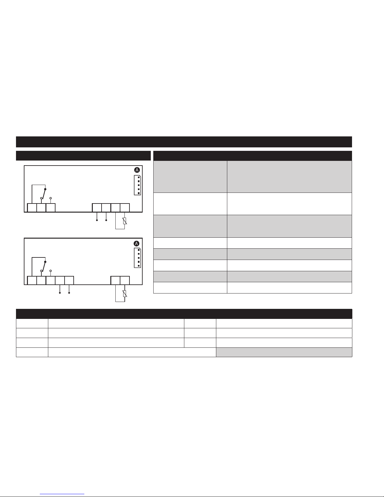
NTC/PTC MODEL
CONNECTIONS
INPUT/OUTPUT CHARACTERISTICS
Display range:
NTC: -50...110°C (-58...230°F)
PTC: -50...140°C (-58...302°F)
on display with 3½ digits + sign
Analogue input
1 NTC or 1 PTC
(selectable by parameter H00)
Serial
TTL for connection to Copy Card or
Televis/Modbus remote control systems
Digital outputs
OUT1: 1 SPDT relay 8(4)A 250 Va
Buzzer output only on models where this is provided
Measurement range -50 ... 140°C (-58 ... 284°F)
Accuracy better than 0.5% of end of scale +1 digit
Resolution 0.1°C (0.1°F up to +199.9°F; 1°F over)
NTC/PTC - 12V, 12-24V
Supply
Pb1
OUT1
1 2 3 8 9 10 11
NTC/PTC - 24V, 115V, 230V
Supply
Pb1
OUT1
1 2 3 4 5 10 11
TERMINALS
1-2 N.C. regulator relay OUT1 *4-5
Power supply 24Va, 115Va and 230Va.
1-3 N.O. regulator relay OUT1 *8-9
Power supply 12V
a/c
and 12-24Va/12-36Vc.
10-11 Probe Pb1 Input
A TTL input for Copy Card and TelevisSystem connection * depends on model
Page 5
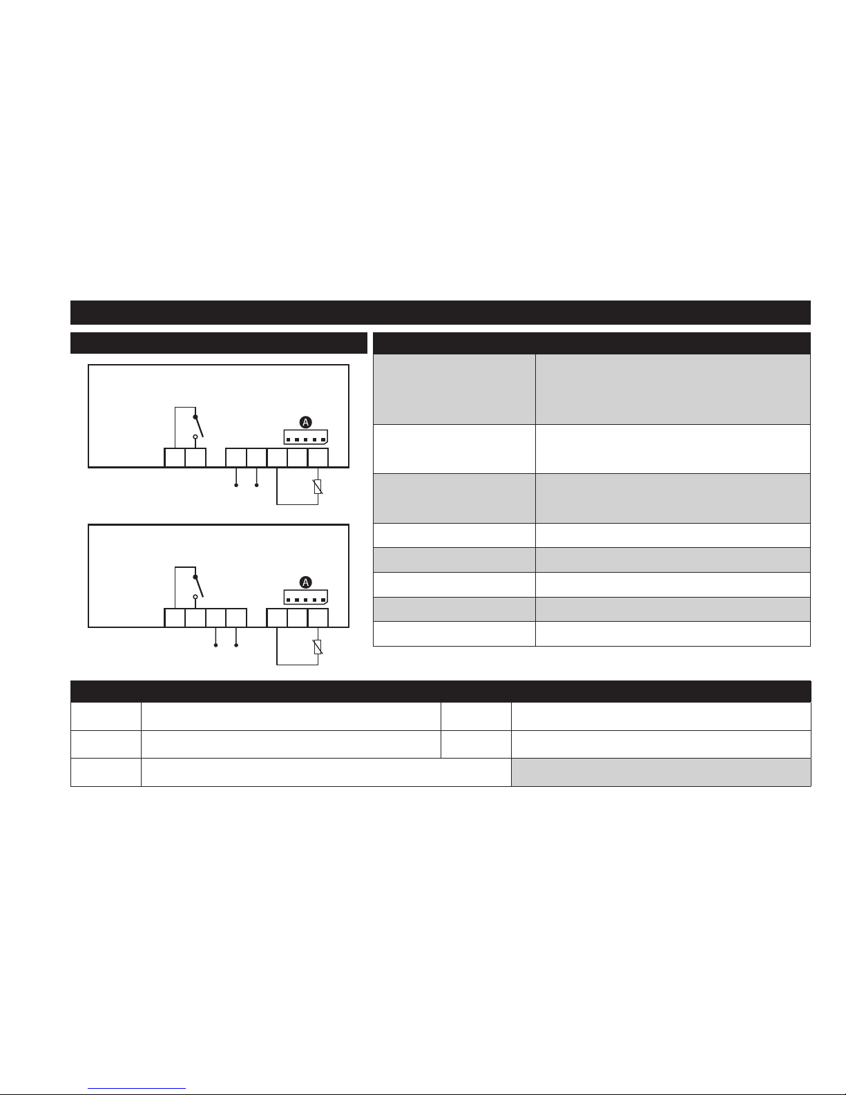
NTC/PTC MODEL (with 2HP relay)
CONNECTIONS
INPUT/OUTPUT CHARACTERISTICS
Display range:
NTC: -50...110°C (-58...230°F)
PTC: -50...140°C (-58...302°F)
on display with 3½ digits + sign
Analogue input
1 NTC or 1 PTC
(selectable by parameter H00)
Serial
TTL for connection to Copy Card or
Televis/Modbus remote control systems
Digital outputs
OUT1: 1 SPST relay 16(8)A 2Hp 250 Va
Buzzer output only on models where this is provided
Measurement range -50 ... 140°C (-58 ... 284°F)
Accuracy better than 0.5% of end of scale +1 digit
Resolution 0.1°C (0.1°F up to +199.9°F; 1°F over)
NTC/PTC - 12V (2 Hp)
Supply
Pb1
OUT1
4 5 7 8 9 10 11
NTC/PTC - 230V (2 Hp)
Supply
Pb1
OUT1
4 5 76 9 10 11
TERMINALS
4-5 N.O. regulator relay OUT1 *6-7
Power supply 24Va, 115Va and 230Va.
9-11 Probe Pb1 Input *7-8
Power supply 12V
a/c
and 12-24Va/12-36Vc.
A TTL input for Copy Card and TelevisSystem connection * depends on model
Page 6
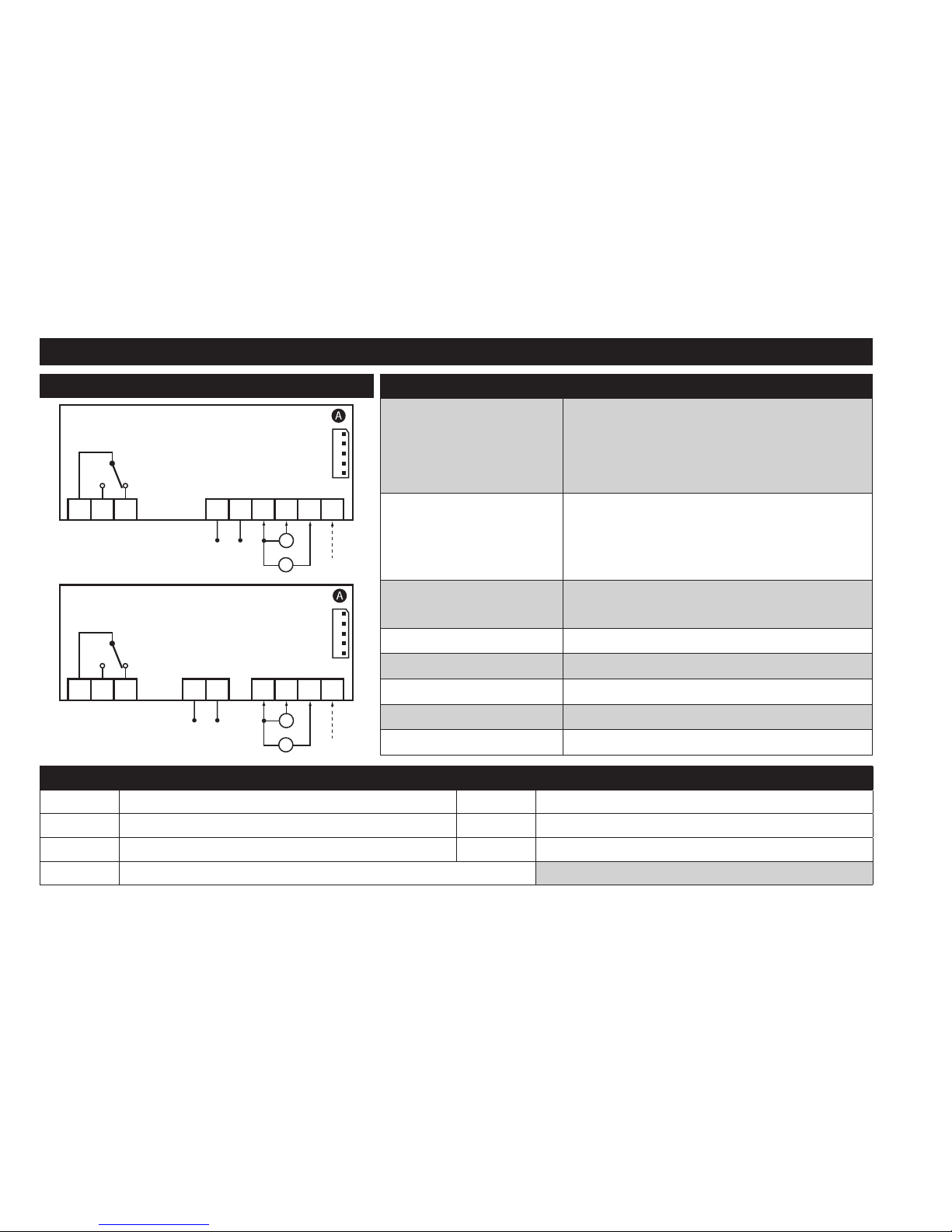
V/I MODEL
CONNECTIONS
INPUT/OUTPUT CHARACTERISTICS
Display range:
-199...199 (ndt = n)
-199.9...199.9 (ndt = y)
-1999...1999 (ndt = int)
on display with 3½ digits + sign
Analogue input
1 V/I (0-1V, 0-5V, 0-10V, 0...20mA, 4...20mA)
(selectable by parameter H00)
Maximum load: - current = 100 Ω
- voltage = 20 kΩ
Serial
TTL for connection to Copy Card or
Televis/Modbus remote control systems
Digital outputs
OUT1: 1 SPDT relay 8(4)A 250 Va
Buzzer output only on models where this is provided
Measurement range -1999 ... 1999
Accuracy better than 0.5% of end of scale +1 digit
Resolution 1 or 0.1 digit according to settings
V/I - 12V, 12-24V
+12V
I
V
+ +−
Supply
OUT1
1 2 3 7 8 9 10 11 12
V/I - 24V, 115V, 230V
+12V
I
V
+ +−
Supply
OUT1
1 2 3 76 9 10 11 12
TERMINALS
1-2 N.O. regulator relay OUT1 *7-8
Power supply 12V
a/c
and 12-24Va/12-36Vc.
1-3 N.C. regulator relay OUT1 *9-10-12 Voltage input (9=GND; 10=”+”; 12=12V)
*6-7
Power supply 24Va, 115Va and 230Va.
*9-11-12 Current input (9=GND; 11=”+”; 12=12V)
A TTL input for Copy Card and TelevisSystem connection * depends on model
Page 7
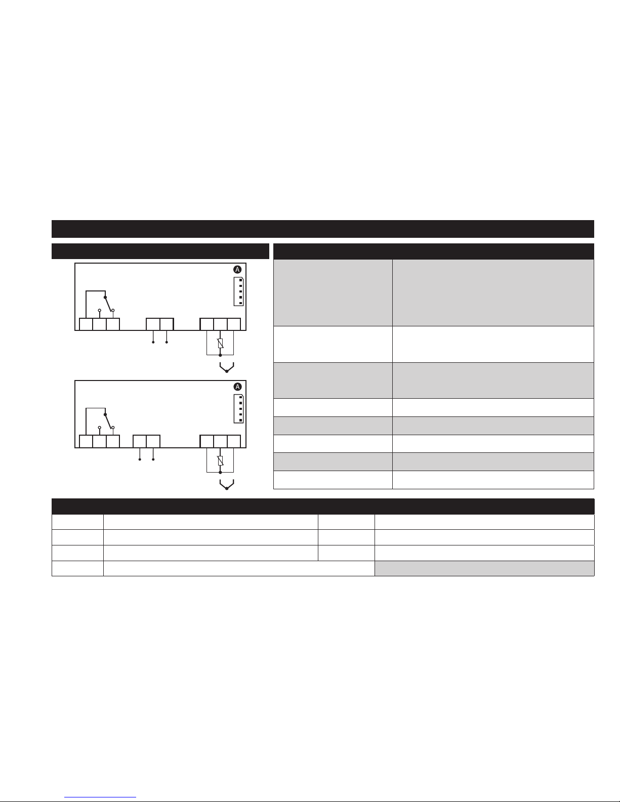
PT100/Tcj-Tck MODEL
CONNECTIONS
INPUT/OUTPUT CHARACTERISTICS
Display range:
PT100: -150...650°C
TcJ: -40...750°C
TcK: -40...1350°C
on display with 3½ digits + sign
Analogue input
1 PT100 or 1 TcJ / Tck
(selectable by parameter H00)
Serial
TTL for connection to Copy Card or
Televis/Modbus remote control systems
Digital outputs
OUT1: 1 SPDT relay 8(4)A 250 Va
Buzzer output only on models where this is provided
Measurement range -150 ... 1350°C (-238 ... 2462°F)
Accuracy see ‘Pt100/TcJ/TcK models’ table
Resolution see ‘Pt100/TcJ/TcK models’ table
PT100/Tcj-Tck - 12V, 12-24V
Supply
Pb1
+
−
1 2 3 6 7 10 11 12
OUT1
PT100/Tcj-Tck - 24V, 115V, 230V
Supply
Pb1
+
−
1 2 3 65 10 11 12
OUT1
TERMINALS
1-2 N.O. regulator relay OUT1 *6-7
Power supply 12V
a/c
and 12-24Va/12-36Vc.
1-3 N.C. regulator relay OUT1 *10-11-12 Probe PT100 input - 3 wires (Pb1)
*5-6
Power supply 24Va, 115Va and 230Va.
*11-12 TcJ/TcK input
A TTL input for Copy Card and TelevisSystem connection * depends on model
Page 8

PT100/Tcj-Tck MODELs
PT100:
ACCURACY:
0.5% for whole scale + 1 digit
0.2% from -150 to 300°C
RESOLUTION: 0.1°C (0.1°F) from -199.9°C up to 199.9°C; 1°C (1°F) beyond
TcJ:
ACCURACY: 0.4% for whole scale + 1 digit
RESOLUTION: 0.1°C (0.1°F) from -199.9°C up to 199.9°C; 1°C (1°F) beyond
Tck:
ACCURACY:
0.5% for whole scale + 1 digit
0.3% from -40 to 800°C
RESOLUTION: 0.1°C (0,1°F) from -199.9°C up to 199.9°C; 1°C (1°F) beyond
MOUNTING - DIMENSIONS
The device is designed for panel mounting. Drill a 29x71 mm hole and insert the instrument; secure it with the special brackets provided. Do not
install the instrument in damp and/or dirty places; in fact, it is suitable for use in places with ordinary or normal levels of pollution.
Keep the area around the instrument cooling slots adequately ventilated.
74 mm
32 mm
29 mm
71 mm
70 mm
59 mm
Page 9

EWPA-EWHS PROBE CONFIGURATION
EWPA 007/030 2 wires / Transducer
Transducer
brown
white
9101112
EWHS 304/314 3 wires
Probe
GND (only EWHS314)
V+
RH/T
9101112
EWHS 284 2 wires
Probe
brown
blue
9101112
EWHS 314 4 wires (V-I model)
Probe
GND
V+
RH
T
GND
ICPlus
1I
CPlus 2
9101112
9101112
Page 10

USING THE COPY CARD
The Copy Card is connected to the serial port (TTL) and allows rapid programming of the instrument parameters. Access Installer parameters by
entering ‘PA2’, scroll through the folders using and until folder FPr appears. Select it using , scroll through the parameters using
and , then select the function using (eg. UL).
• Upload (UL):
Select UL and press . This function uploads the programming parameters from the instrument to the card. If the
procedure is a success, ‘y’, will appear on the display, otherwise ‘n’ will appear.
• Format (Fr): This command is used to format the copy card (recommended when using the card for the first time).
Important: the Fr parameter deletes all data present. This operation cannot be cancelled.
• Download: Connect the Copy Card when the instrument is switched off. At power-on, data is downloaded from the copy card to the
instrument automatically. At the end of the lamp test, the display will show ‘dLy’ if the operation was successful and ‘dLn’
if not.
UPLOAD
DOWNLOAD
OR
NOTE: After downloading, the instrument works with the settings of the new map just downloaded.
Page 11

ACCESSING AND USING THE MENUs
The resources are organized into 2 menus which are accessed as follows:
• ‘Machine Status’ menu: press and release the key.
• ‘Programming’ menu: hold down the key for 5 seconds.
Either do not press any keys for 15 seconds (timeout) or press the key once, to confirm the last value displayed and return to the previous
screen.
PASSWORD
Password ‘PA1’: used to access User parameters. The password is not enabled by default (PS1=0).
To enable it (PS1≠0): press and hold for longer than 5 seconds, scroll through the parameters using and until you see the label
PS1, press to display the value, modify it using and , then save it by pressing or . If enabled, it will be required in
order to access the User parameters.
Password ‘PA2’: used to access Installer parameters. The password is enabled by default (PS2=15).
To modify it (PS2≠15): press and hold for longer than 5 seconds, scroll through the parameters using and until you see the
label PA2, press , set the value to ‘15’ using and , then confirm using . Scroll through the folders until you find the label
diS and press to enter. Scroll through the parameters using and until you see the label PS2, press to display the value,
modify it using and , then save it by pressing or .
The visibility of ‘PA2’ is as follows:
1) PA1 and PA2 ≠ 0: Press and hold for longer than 5 seconds to display PA1 and PA2. It will then be possible to decide whether to
access the User parameters (PA1) or the Installer parameters (PA2).
2) Otherwise: The password PA2 is amongst the level1 parameters. If enabled, it will be required when accessing the Installer
parameters; to enter it, proceed as instructed for password PA1.
If the value entered is incorrect, the label PA1/PA2 will be displayed again and the procedure will need to be repeated.
Page 12

MACHINE STATUS MENU
Access the Machine Status menu by pressing and releasing the key. If no alarms are active, the ‘SEt’ label appears.
Use the keys and to scroll through all the folders in the menu:
- AL: alarms folder (only visible if an alarm is active);
- SP1: Setpoint 1 setting folder;
- Pb1: probe 1 - Pb1 folder;
Setting the Setpoint:
To display the Setpoint value press the key when the ‘SEt’ label is displayed.
The Setpoint value appears on the display. To change the Setpoint value, press the and keys within 15
seconds. Press to confirm the modification.
Displaying probes:
When label Pb1 is present, press the key to view the value measured by the corresponding probe (NOTE:
the value cannot be modified).
PROGRAMMING MENU
To access the ‘Programming’ menu, press the key for more than 5 seconds. If specified, an access PASSWORD
will be requested: ‘PA1’ for User parameters and ‘PA2’ for Installer parameters (see ‘PASSWORD’ paragraph).
User Parameter: When accessed, the display will show the first parameter (e.g. ‘diF’). Press and to scroll through all the parameters on
the current level. Select the desired parameter by pressing . Press and to modify it and to save the changes.
Installer Parameter: When accessed, the display will show the first folder (e.g. ‘CP’). Press and to scroll through the folders on the
current level. Select the desired folder using . Press and to scroll through the parameters in the current folder and select the
parameter using . Press and to modify it and to save the changes.
NOTE: Make sure you switch the instrument off and on again each time the parameter configuration is changed, in order to prevent mal-
functioning in the configuration and/or timing in progress.
Page 13

DIAGNOSTICS
Alarms are always indicated by the alarm icon and the buzzer.
To switch off the buzzer, press and release any key; the corresponding icon will continue to flash.
N.B.: If alarm exclusion times have been set (see ‘AL’ folder in the parameters table) the alarm will not be signalled.
ALARMS
Label Fault Cause Effects Remedy
E1
Probe1 faulty
(ambient)
• measured values are outside
operating range
• Probe faulty/short-circuited/open
• Display label E1
• Alarm icon permanently on
• Disable max/min alarm controller
• Compressor operation based on
parameters On1 and OF1
• check probe type (H00)
• check probe wiring
• replace probe
AH1
Alarm for HIGH
value (Probe1)
value read by Pb1 > HA1 after
time of tAO.
• Recording of label AH1 in folder AL
• No effect on regulation
Wait until value read by Pb1
returns below HA1.
AL1
Alarm for LOW
value (Probe1)
value read by Pb1 < LA1 after
time of tAO.
• Recording of label AL1 in folder AL
• No effect on regulation
Wait until value read by Pb1
returns above LA1.
Page 14

TELEVIS SYSTEM
The Televis remote control systems can be connected using the
TTL serial port (TTL-RS485 BusAdapter 130 or 150 interface
module must be used).
To configure the instrument to do this, you need to access the
Add folder and use the dEA and FAA parameters.
RS485
BusAdapter
ICPlus
TTL
IMPORTANT! CHECK THE AVAILABILITY OF MODELS
COMPATIBLE WITH REMOTE SUPERVISION SYSTEMS.
DUTY CYCLE DIAGRAM
The device uses parameters On1 e OF1 set for Duty Cycle.
An error condition in probe1 (regulation) causes one of the following actions:
• Code ‘E1’ is shown on the display
• The regulator is activated as indicated by parameters On1 and OF1 if set for Duty Cycle
On1 OF1 Regulator output
0 0 OFF
0 >0 OFF
>0 0 ON
>0 >0 Duty Cycle
OF1
OFFON
OUT
On1 On1
ON
Page 15

TECHNICAL DATA (EN 60730-2-9)
Classification: operation (not safety) device for incorporation
Mounting: panel mounting with 71x29 mm (+0.2/-0.1 mm) drilling template
Type of action: 1.B
Pollution class: 2
Material class: IIIa
Overvoltage category: II
Rated impulse voltage: 2500V
Temperature: Operating: –5 … +55 °C - Storage: –30 … +85 °C
Power supply:
• 12Va/c (±10%)
• 24 Va ±10%
• 12-24Va/12-36Vc ±10%
• 115Va ±10% 50/60 Hz
• 230 Va ±10% 50/60 Hz
Consumption:
• 1.5 VA max (model 12Va/c)
• 3 W max (models: 24Va, 12-24Va/12-36Vc, 115Va and 230Va)
Digital outputs (relay): refer to the label on the device
Fire resistance category: D
Software class: A
NOTE: check the power supply specified on the instrument label.
Page 16

FURTHER INFORMATION
Input/Output Characteristics
See ‘Connections’ section
Mechanical Characteristics
Casing: PC+ABS UL94 V-0 resin casing, polycarbonate window, thermoplastic resin keys
Dimensions: front panel 74x32 mm, depth 59 mm (without terminals)
Terminals: screw/disconnectable terminals for cables with a diameter of 2,5mm
2
Connectors: TTL for connection of Unicard/Copy Card
Humidity: Operating / Storage: 10…90 % RH (non-condensing)
Regulations
Electromagnetic compatibility: The device conforms to Directive 2004/108/EC
Safety: The device conforms to Directive 2006/95/EC
Food Safety: The device complies with standard EN13485 as follows:
• suitable for storage
• application: air
• climate range A
• measurement class 1 in the range from -25°C to 15°C (*)
(* exclusively using Eliwell probes)
NOTE: The technical specifications given in this document regarding measurement (range, accuracy, resolution, etc.) refer
to the instrument and not to any accessories provided, such as the probes. This means, for example, that the error introduced
by the probe must be added to the typical error of the instrument.
Page 17

PARAMETERS TABLE
PAR. DESCRIPTION MODEL RANGE VALUE M.U. LEVEL
SP1
Temperature control setpoint SP1. The SEtpoint is visible from the
machine status menu and not from the programming menu.
NTC/PTC
LS1...HS1
0.0 °C/°F
PT100-Tc 0.0 °C/°F
V/I 0 num
CONTROLLER 1 (folder ‘rE1’)
HC1
This sets the controller 1 operating mode.
H (0) = Hot; C (1) = Cold.
ALL H/C H flag Inst
OS1 Temperature value to be added to SP1 if reduced set enabled
NTC/PTC -30.0...30.0 0.0 °C/°F
InstPT100-Tc -30.0...30.0 0.0 °C/°F
V/I -30...30 0 num
dF1
OUT1 activation differential.
The utility stops on reaching the SP1 value (as indicated by control probe) and
restarts at a temperature value equal to T=SP1+dF1 relative to HC1.
NTC/PTC 0.0...30.0 1.0 °C/°F
User/InstPT100-Tc 0.0...30.0 1.0 °C/°F
V/I 0...30 1 num
HS1 Maximum value assignable to setpoint SP1.
NTC/PTC
LS1...HdL
140.0 °C/°F
User/InstPT100-Tc 1350 °C/°F
V/I 199 num
LS1 Minimum value assignable to setpoint SP1.
NTC/PTC
LdL...HS1
-50.0 °C/°F
User/InstPT100-Tc -199.9 °C/°F
V/I -199 num
HA1
Maximum temperature alarm on OUT1.
(See ‘Max/Min temperature alarms’)
NTC/PTC LA1...150.0 140.0 °C/°F
InstPT100-Tc LA1...1999 1350 °C/°F
V/I LA1...150 150 num
LA1
Minimum temperature alarm on OUT1.
(See ‘Max/Min temperature alarms’)
NTC/PTC -150.0...HA1 -50.0 °C/°F
InstPT100-Tc -328...HA1 -199.9 °C/°F
V/I -150...HA1 -150 num
dn1
Switch-on delay. The indicated time must elapse between the request for
activation of the controller 1 relay and switch-on. 0 = not active.
ALL 0...250 0 min Inst
Page 18

PAR. DESCRIPTION MODEL RANGE VALUE M.U. LEVEL
dO1
Delay time after switching off. The indicated time must elapse between
deactivation of the controller 1 relay and the next switch-on. 0 = not active.
ALL 0...250 0 min Inst
di1
Delay between switch-ons. The indicated time must elapse between two
consecutive switch-ons of regulator 1. 0 = not active.
ALL 0...250 0 min Inst
dE1
Switch-off delay. The indicated time must elapse between the request for
deactivation of the controller 1 relay and switch-off. 0 = not active.
ALL 0...250 0 min Inst
On1
Controller 1 switch-on time in the event of faulty probe.
if On1=1 and OF1=0, the controller remains on;
if On1=1 and OF1>0, the controller operates in Duty Cycle mode.
ALL 0...250 0 min Inst
OF1
Controller 1 switch-off time in the event of faulty probe.
if OF1=1 and On1=0, the controller remains off;
if OF1=1 and On1>0, the controller operates in Duty Cycle mode.
ALL 0...250 1 min Inst
ALARMs (folder ‘AL’)
AFd Alarm differential.
NTC/PTC 1.0...50.0 2.0 °C/°F
InstPT100-Tc 1.0...50.0 2.0 °C/°F
V/I 1...50 2 num
tP Enable all keys to acknowledge an alarm. n (0) = no; y (1) = yes. ALL n/y y flag Inst
COMMUNICATION (folder ‘Add’)
PtS Selection of communication protocol. t = Televis; d = Modbus. ALL t/d t flag Inst
dEA Index of the device within the family (valid values from 0 to 14). ALL 0...14 0 num Inst
FAA Device family (valid values from 0 to 14). ALL 0...14 0 num Inst
Adr Modbus protocol controller address. ALL 1...255 1 num Inst
bAU
Baudrate selection.
48 (0) = 4800; 96 (1) = 9600; 192 (2) = 19200; 384 (3) = 38400.
ALL
48/96/
192/384
96 num Inst
Pty Modbus parity bit. n (0) = none; E (1) = even; o (2) = odd. ALL n/E/o E num Inst
StP Modbus stop bit. 1b (0) = 1 bit; 2b (1) = 2 bit. ALL 1b/2b 1b flag Inst
Page 19

PAR. DESCRIPTION MODEL RANGE VALUE M.U. LEVEL
DISPLAY (folder ‘diS’)
LOC
LOCk. Setpoint edit lock. The parameter programming menu can still be
accessed, and the settings changed, which means also that the status of this
parameter can be changed so as to unlock the keypad. n (0)= no; y (1) = yes.
ALL n/y n flag User/Inst
PS1
Password 1. When enabled (PS1 ≠ 0) it is the password to the ‘User’
parameters (User).
ALL 0...250 0 num User/Inst
PS2
Password 2. When enabled (PS2 ≠ 0) it is the password to the ‘Installer’
parameters (Inst).
ALL 0...250 15 num Inst
ndt
Display values with decimal point. n (0) = no (integers only);
y (1) = yes (displayed with decimal point); int (2) = integer.
ALL n/y/int n num User/Inst
CA1
Calibration 1. Positive or negative temperature value added to the value read by
Pb1, according to the setting of parameter CAI.
NTC/PTC -30.0...30.0 0.0 °C/°F
User/InstPT100-Tc -30.0...30.0 0.0 °C/°F
V/I -30...30 0 num
CAI
Intervention of the offset on display, temperature control or both.
0 = only the temperature shown is modified;
1 = sum with only the temperature used by the controllers and not for the
display, which remains unchanged;
2 = sum with the displayed temperature, which is also used by the regulators.
ALL 0/1/2 2 num Inst
LdL Minimum value that can be displayed by the device.
NTC/PTC -199.9...HdL -50.0 °C/°F
Inst
PT100-Tc -328...HdL -199.9 °C/°F
V/I -199...HdL -199 num
HdL Maximum value that can be displayed by the device.
NTC/PTC LdL...199.9 140.0 °C/°F
InstPT100-Tc LdL...1350 1350 °C/°F
V/I LdL...199 199 num
dro
Select the unit of measurement of probe 1.
• NTC/PTC and PT100-Tc: C (0) = °C, F (1) = °F
• V/I: n (0) = no unit of measure selected,
t (1) = temperature, P (2) = pressure, H (3) = humidity
NTC/PTC C/F C flag
InstPT100-Tc C/F C flag
V/I n/t/P/H n num
Page 20

PAR. DESCRIPTION MODEL RANGE VALUE M.U. LEVEL
CONFIGURATION (folder ‘CnF’) If one or more parameters are changed, the controller MUST be switched off and switched on again.
H00
Probe type selection.
• NTC/PTC: Ptc (0) = PTC, ntC (1) = NTC
• PT100-Tc: Jtc (0) = TcJ, Htc (1) = Tck, Pt1 (2) = PT100.
• V/I: 420 (0) = 4...20mA, 020 (1) = 0...20mA, t10 (2) = 0...10V,
t05 (3) = 0...5V, t01 (4) = 0...1V.
NTC/PTC Ptc/ntC ntc flag
User/Inst
PT100-Tc Jtc/Htc/Pt1 Jtc num
V/I
420/020
t10/t05/t01
420 num
H02
Press the ESC, UP and DOWN keys (if configured for a second function) for the
time H02 to activate the function itself.
N.B.: The AUX function has a fixed activation time of 1 second.
ALL 0...15 5 secs Inst
H03
Lower input current/voltage limit.
(only present on model V/I)
NTC/PTC
User/Inst
PT100-Tc
V/I -1999...1999 0 num
H04
Upper current/voltage limit for input.
(only present on model V/I)
NTC/PTC
User/InstPT100-Tc
V/I -1999...1999 1000 num
H05
Window filter:
-2 = very fast; -1 = fast; 0 = normal; 1 = slow; 2 = very slow.
ALL -2/-1/0/1/2 0 num Inst
H06
Key or Digital Input with aux/light or door switch active with the device OFF (but
powered). n (0) = not active; y (1) = active.
ALL n/y y flag Inst
H08
Stand-by operating mode.
0 = only display switches off; 1 = display on and controllers locked;
2 = display off and controllers locked.
ALL 0/1/2 2 num Inst
H10
Delay for output activation after Power On. If H10 = 0 the delay is NOT active; if
H10 ≠ 0 the output will not be activated before this time has expired.
ALL 0...250 0 min Inst
H31
Configuration of UP key.
0 = disabled; 1 = SOFT START; 2 = Offset setpoint; 3 = Outputs stopped;
4 = Periodic cycle; 5 = AUX output; 6 = Stand-by; 7 = not used.
ALL 0...7 0 num Inst
H32 Configuration of DOWN key. Same as H31. ALL 0...7 0 num Inst
Page 21

PAR. DESCRIPTION MODEL RANGE VALUE M.U. LEVEL
H33 Configuration of ESC key. Same as H31. ALL 0...7 6 num Inst
rEL firmware version. Device software release: read-only parameter. ALL / / / User/Inst
tAb Parameters table. Reserved: read-only parameter. ALL / / / User
COPY CARD (folder ‘FPr’)
UL Upload. Transfer of programming parameters from instrument to Copy Card. ALL / / / Inst
dL Download. Transfer of programming parameters from Copy Card to instrument. ALL / / / Inst
Fr
Format. Cancels all data entered in the Copy Card.
IMPORTANT: If parameter Fr (Copy Card formatting) is used, the data entered
in the card will be permanently lost. This operation cannot be reversed.
ALL / / / Inst
FUNCTIONS (folder ‘FnC’)
Function Function label ACTIVE Function label NOT ACTIVE D.I. KEY Alarm signaling
Reduced setpoint OSP SP 2 2 ON Icon
Stand-by On OF 6 6 ON Icon
Alarm acknowledgement tAL tAL 7 7 ON Icon
NOTES: - to modify the status of a given function, press the ‘set’ key
- If the instrument is switched off, the function labels will return to the default status
Page 22

ELECTRICAL CONNECTIONs
Attention! Make sure the machine is switched off before working on the electrical connections.
The instrument is equipped with screw or disconnectable terminal blocks for connecting electrical cables with a max.
diameter of 2.5 mm2 (one wire per terminal for power connections): for the terminal ratings, see the label on the instrument.
Do not exceed the maximum permissible current; in case of higher loads, use a suitably rated contactor.
Make sure the power supply voltage complies with that required by the instrument. Probes have no connection polarity and
can be extended using a normal bipolar cable (Note that extending the probes burdens the behaviour of the instrument in
terms of EMC electromagnetic compatibility: specifically, if Pt100 probes with cable longer than 3 mt are used, an extreme
care must be taken during wiring operations).
Probe cables, power supply cables and the TTL serial cable should be routed separately from power cables.
CONDITIONS OF USE
Permitted use
For safety reasons, the instrument must be installed and used according to the instructions supplied and, in particular, parts
under dangerous voltages must not be accessible in normal conditions.
The device must be adequately protected from water and dust with regard to its application, and must only be accessible
using tools (except for the front panel). The device is suitable for use in household refrigeration appliances and/or similar
equipment and has been tested for safety aspects in accordance with the harmonised European reference standards.
Improper use
Any use other than that expressly permitted is prohibited. The relay contacts provided are of a functional type and subject
to failure: any protection devices required by product standards, or suggested by common sense for obvious safety
requirements, must be installed externally to the instrument.
Page 23

LIABILITY AND RESIDUAL RISKS
ELIWELL CONTROLS SRL declines any liability for damage due to:
• installation/uses different from those specified and, in particular, not complying with the safety regulations and/or
instructions given in this document;
• use on panels that do not provide adequate protection against electric shocks, water or dust when assembled;
• use on panels allowing access to dangerous parts without the use of tools;
• tampering with and/or modifying the product;
• installation/use on panels not complying with current standards and regulations.
DISCLAIMER
This document is the exclusive property of ELIWELL CONTROLS SRL and may not be reproduced or circulated unless expressly
authorised by ELIWELL CONTROLS SRL itself.
Every care has been taken in preparing this document; nevertheless ELIWELL CONTROLS SRL cannot accept liability for
any damage resulting from its use. The same applies to any person or company involved in preparing and editing this
document. ELIWELL CONTROLS SRL reserves the right to make aesthetic or functional changes at any time without notice.
DISPOSAL
The appliance (or the product) must be disposed of separately in compliance with the local standards in
force on waste disposal.
Page 24

Eliwell Controls s.r.l.
Via dell’Industria, 15 - Z.I. Paludi
32010 Pieve d’Alpago (BL) ITALY
Telephone: +39 0437 986 111
Facsimile: +39 0437 989 066
www.eliwell.com
Technical Customer Support:
Technical helpline: +39 0437 986 300
E-mail: techsuppeliwell@invensys.com
Sales
Telephone: +39 0437 986 100 (Italy)
+39 0437 986 200 (other countries)
E-mail: saleseliwell@invensys.com
cod. 9IS44315-1 • ICPlus 902 • EN • rel. 09/13
© Eliwell Controls s.r.l. 2013 • Tutti i diritti riservati.
 Loading...