

Page 1
BUTTONS AND MENUS ACCESSING
AND USING MENUS
The resources are arranged in a menu that
can be accessed by pressing and quickly
releasing the “set” button (Machine Status
menu) or holding down the “set” button
for more than 5 seconds (Programming
menu).
To access the contents of each folder indicated by the relevant label, just press the
“set” button once.
You can now scroll through the contents
of each folder, modify it or use its functions. If you do not use the keyboard for
over 15 seconds (time-out) or if you press
the “fnc” button once, the last value
shown on the display is confirmed and you
are taken back to the previous screen
mask.
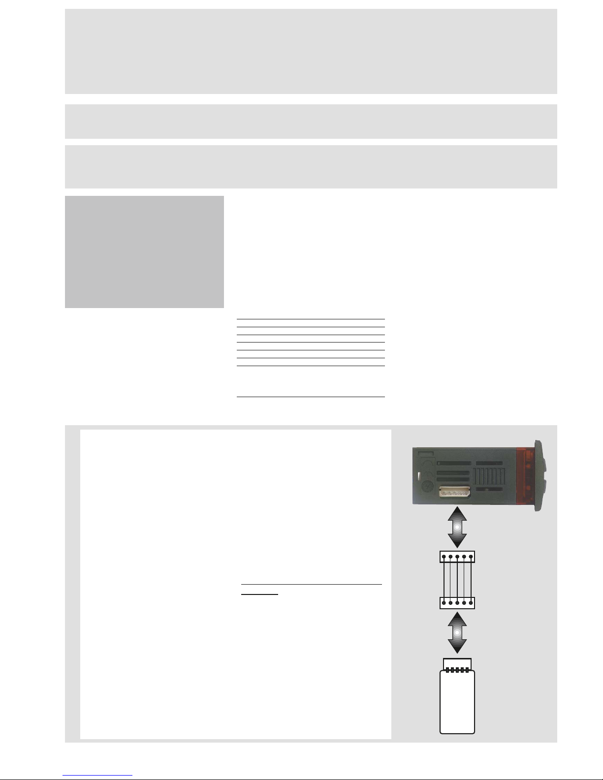
MACHINE STATUS MENU
(See Machine Status Menu Diagram)
To access the Machine Status menu, press
the “set” button and quickly release it.
The “SP1” label appears.
(If alarms are active, with the exception of
faulty probes/probe errors, the “AL” label
appears).
By using the “UP” and “DOWN” buttons
you can scroll through the other folders in
the menu: the folders are indicated below
in the order they appear:
-SP1: Set point 1 setting folder or
-AL: alarm folder (if alarms present, with
exception of faulty probes/probe errors);
-SP2: Set point 2 setting folder.
-Pb1: probe 1 value folder;
-Pb2: probe 2 value folder;
The folders are present according to
the presence and configuration of the
associated resource.
Alarm on
If an alarm condition exists when the
Machine Status menu is accessed, the “AL”
folder label appears (see “Diagnostics”
section).
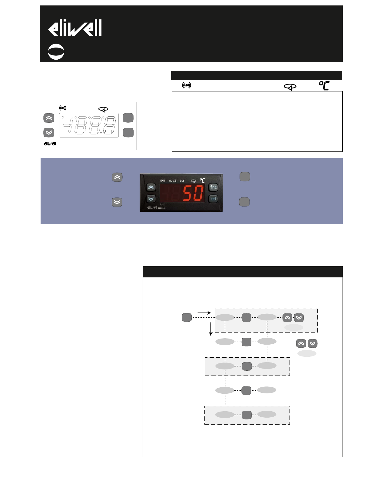
USER INTERFACE
The user has a display and four buttons
for controlling instrument status and programming.
IC 915 (LX)
electronic controller with 2 set points and differential set point
adjustment
cod. 9IS23071
rel. 12/04
GB
Alarm
•ON for active
alarm;
•blinking when
a silenced alarm
is still present
out2
Relay 2 (OUT2)
ON for relay on
(energized);blin
king for protec-
tion delay or
enabling
blocked
out1
Relay 1 (OUT1)
ON for relay on
(energized);blin
king for protec-
tion delay or
enabling
blocked
Soft Start
ON when Set
point is being
set
(and Set point
setting)
blinking when
Soft Start func-
tion is on
Set-point/
Reduced set
point
•ON to modify
Set-Point;
•blinking when
reduced set
point is entered
set
f nc
IC915LX
out 2
out 1
AL
SP1
SP2
set
alarms
value SP1
value SP2
set
set
set
change
SP1(2) value
show alarms
is present
press and release
(quickly/single press)
if alarm(s)
present
Pb1
Pb2
value Pb1
value Pb2
set
set
is present
MACHINE STATUS MENU DIAGRAM
LEDs
out2 out1
Scrolls through the menu items UP button
Increases the values
Parameter programmable
(par. H31)
DOWN button
Scrolls through the menu items
Decreases the values
Parameter programmable
(par. H32)
fnc button ESC function (quit)
Parameter programmable
(par. H33)
Set point button 1-Accesses Machine Status Menu
(SET POINTS, ACTIVE ALARMS,
PROBE READING) and labels/values;
1-Accesses Programming Menu
(PARAMETERS, COPY C ARD) and
relative labels/values;
3-Confirms commands
fnc
set
Page 2
*FNC FUNCTION FOLDER
The FnC folder (last folder visible from
the Programming Menu, level 1) contains the following functions. They are
activated using the “set” button
If the unit is switched off, the function
labels go back to their default status.
ADVANCED FUNCTIONS
DIFFERENTIAL AND SET POINT OFF
DIFFERENTIAL AND SET POINT OFF--
SET ADJUSTMENT (see relevant para
SET ADJUSTMENT (see relevant para--
graph)
graph)
SOFT START
Note: The SOFT START function is button, D.I. or function selectable.
The Soft Start controller can be used to
set the temperature gradient required to
reach a specific set point in a specific period of time.
This function automatically gives you a
progressive increase of the control set
point from the Ta value (ambient temperature at start-up) to the value actually displayed. This means that a rise in temperature can be immediately stopped and the
risk of overshooting reduced. (continued
on pg. 4)
IC 915 LX 2/10
Function
Soft Start
Reduced set point
Controls blocked
Periodic Cycle
Aux
Stand-by
Maintenance
request
NOTE: In this case the UnP label is displayed
(flashing)
**default
Function label
INACTIVE
SoF**
SP**
boF
coF
AoF
oF
AtF**
Function label
ACTIVE
Son
OSP
bon**
con
Aon
on**
Atn
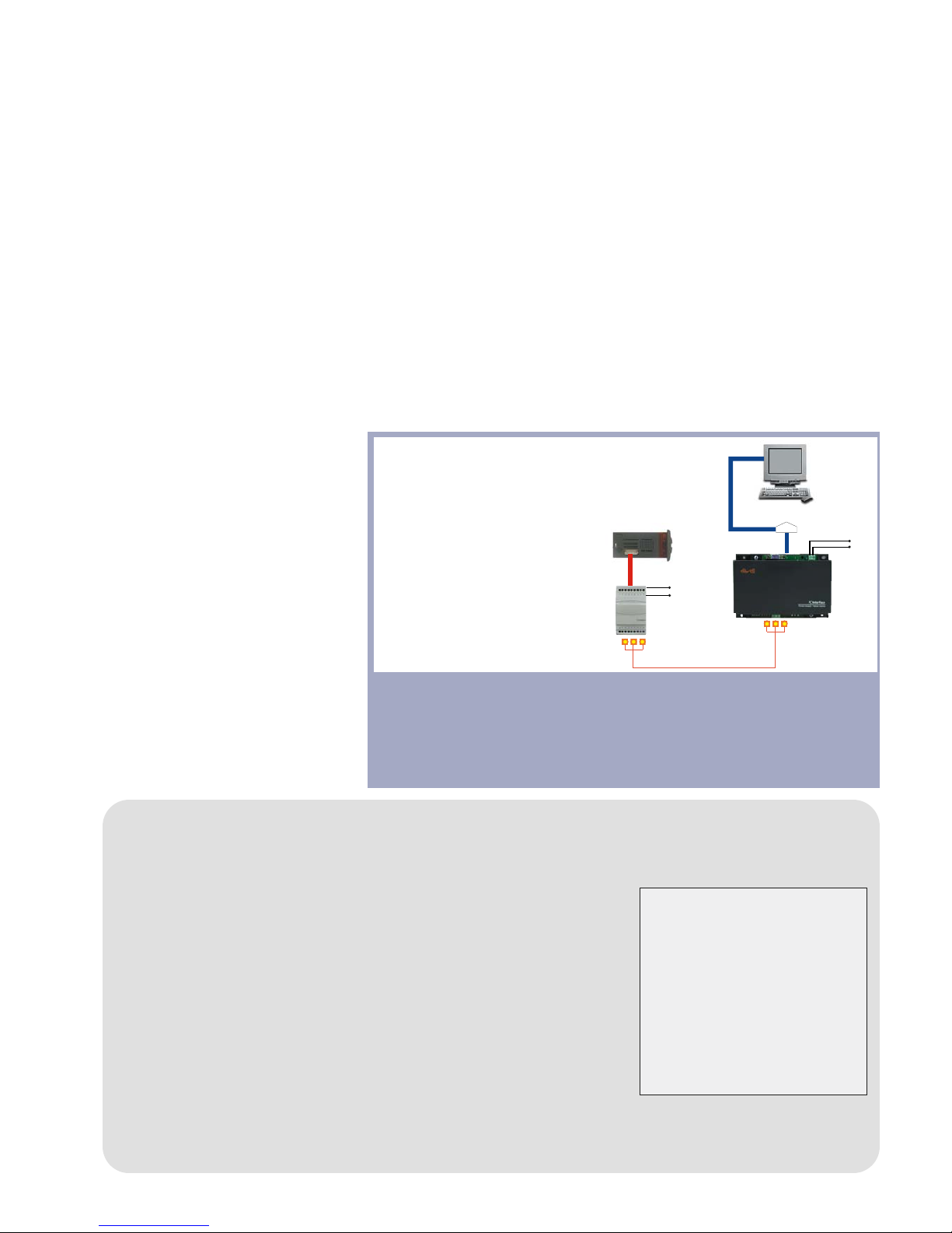
USING COPY CARD
The Copy Card is an accessory connected to the TTL serial port used for quick
programming of the unit parameters
(upload and download parameter map
to one or more units of the same type).
Operations are described below:
Fr-Format
This command is used to format the
copy card. This is necessary if:
•it is used for the first time,
•it is used with models that are incompatible,
•after use with a specific model if
another model needs to be connected.
Warning: when the copy card has been
programmed using the “Fr” parameter
all the data entered is cancelled. This
operation cannot be undone.
UL-Upload
This operation uploads the programming
parameters from the instrument.
dL-Download
This operation downloads the programming parameters to the instrument.
NOTE:
• UPLOAD: instrument —> Copy Card
• DOWNLOAD: Copy Card —> instrument.
The operations are performed by accessing the folder identified by the “FPr”
label and selecting the “UL”, “dL” or “Fr”
commands. The operation is confirmed
by pressing the “set” button. If the operation is successful, a “y” is displayed
whereas if it is unsuccessful an “n” will
be displayed.
Download “from reset”
Connect the copy card with the instru
ment OFF. When the instrument is
switched on the programming parameters will be downloaded into the copy
card; when the lamp test has been completed, the following appear on the display for about 5 seconds:
• label dLY if copy operation is successful
• label DLn if operation fails
PLEASE NOTE:
• after downloading the instrument will
work with the parameter map settings
that have just been downloaded.
HOW TO LOCK THE KEYBOARD
Keyboard operating can be locked by programming the “LOC” parameter (see folder
with “diS” table).
If the keyboard is locked you can only
access the Programming MENU (see)
Functions CANNOT be activated with buttons (to silence alarms, for example) .
HOW TO SET THE SET POINTS
Setting Setpoint 1 (Setpoint 2)
Go to the “Machine Status” menu, press the “set” button and quickly release it. The “SP1” folder label appears.
(To set Set point 2 press the “UP“ and “DOWN“ buttons until “SP2” appears). To display the Set point 1 (2) value, press the “set” button again.
The Set point value appears on the display. To change the Set point 1 (2) value, press the “UP” and “DOWN” buttons within 15 seconds.
If parameter LOC = y the Set points cannot be changed.
HOW TO DISPLAY THE TEMPERATURE READ BY PROBE(S)
If you press the “set” button when the corresponding label appears, the value of the probe associated with it is displayed.
ALARM PRESENT?
If an alarm condition exists when the Machine Status menu is accessed, the “AL” folder label appears. which will include the alarm
codes. (see section on “Diagnostics”).
Page 3

IC 915 LX 3/10
PROGRAMMING MENU
(See Programming Menu Diagram)
1) Displaying level 1 parameters
To access the Programming menu, hold
the “set” button for more than 5 seconds.
Level 1 parameters can be protected by a
PASSWORD* (defined by parameter
DIS/PA1) If the PASSWORD is enabled,
the label “PA1” will appear when you
access the Programming Menu; press
the “set” button and the value “0” will
appear; enter the password using the
“UP”/”DOWN” buttons and press the
“set” button again. This allows you to
access the level 1 parameters.
The first folder that appears is “CP”.
Use the “UP” and “DOWN” buttons to
scroll through the other folders; the
folders will only display level 1 parameters.
NOTE: at this point level 2 parameters
are NOT visible even if NOT passwordprotected.
2) Displaying level 2 parameters
Go to the “CnF” folder in the
Programming Menu and scroll down the
parameters until you reach the PA2 label.
By pressing and releasing the “set” button you will enter the level 2 parameters
and the “CP” label of the first folder in
the programming menu will appear.
The level 2 parameters can be protected
by a second PASSWORD* (defined by
parameter DIS/PA2)
(NOTE: not to be confused with the PA2
label in the “CnF” folder).
If the PASSWORD is enabled, the label
“PA2” will appear in CnF/PA2 when you
access the Programming Menu; press
the “set” button and the value “0” will
appear; enter the password using the
“UP”/”DOWN” buttons and press the
“set” button again. This allows you to
access the level 2 parameters. The first
folder that appears is “CP”.
NOTE: At this level the folders will
only display all the level 2 parameters.Therefore level 1 parameters will
only be visible if you quit the
Programming Menu and repeat procedure 1).
NOTE: It is strongly recommended that
the unit is switched off and on again
each time parameter configuration is
changed in order to prevent malfunctioning of the configuration and/or
ongoing timings (compulsory for selec-
tion of probe type and count parameters).
*PASSWORD
Passwords “PA1” and “PA2” allow level 1
and level 2 parameters to be accessed.
There are no passwords in the standard
configuration. To enable them (value ≠0)
and assign them the desired value, access
the Programming menu in the “diS” folder. If passwords are enabled, they will be
requested:
- PA1 when entering the Programming
menu (see the “Programming Menu“ section);
- PA2 in the “Cnf” folder containing the
level 1 parameters.
AL
level 1 par
set
set
PA1≠0
set
set PA1 value
Add
diS
CnF
Fpr
set
level 1 par
level 1 par
level 1 par
level 1 par
set
set
set
PA2
level 2 par
level 2 par
level 2 par
level 2 par
level 2 par
level 2 par
level 2 par
rE1/2
SFt
cLc
AL
set
set
set
set
diS
CnF
Fpr
set
set
set
set
set
PA2≠0
set
set PA2 value
level 2
level 1
change
par value
scroll
parameters
FnC
functions
set
scroll
functions
activate/disactivate
function
set
press for 5 sec
rE1
rE2
set
level 1 par
level 1 par
set
if folder
present
PROGRAMMING MENU DIAGRAM
Page 4
TECHNICAL DATA
Front protection: IP65.
Casing: PC+ABS UL94 V-0 resin plastic
body, polycarbonate front, thermoplastic
resin buttons.
Dimensions: front panel 74x32 mm, depth
59 mm (terminals excluded).
Mounting: on panel, with drilling template
71x29 mm (+0.2/-0.1 mm).
Operating temperature: -5…55 °C.
Storage temperature: -30…85 °C.
Usage ambient humidity: 10…90 % RH
(non-condensing).
Storage ambient humidity: 10…90% RH
(non-condensing).
Display range:
• NTC probe: –50…110°C (–58…230°F);
• PTC probe: –55…150°C (–67…150.00°C)
on display 3 1/2 digits + sign.
Analogue inputs: two PTC or NTC inputs
(H00 parameter-selectable).
Digital input: 1 voltage-free parameterconfigurable digital input.
Serial: TTL for connection to Copy Card
and Televis System.
Digital outputs: 1 output on SPDT relay
8(3)A 1/2 hp 250Va, 1 output on SPST
relay 8(3)A 1/2 hp 250Va configurable
(for relay capacity, see instrument label).
Buzzer output: only in certain models.
Measurement range: from -55 a 150 °C.
Accuracy: better than 0.5% of bottom scale
+ 1 digit.
Resolution: 1°C or 0.1°C (displayed with
decimal point).
Consumption:
• 230V model: 3 VA max.;
• 12/24V model: 1.5 VA max.
Power supply: 12/24 Va/c ±10% or
230Va ±10% 50/60 Hz.
Warning: check the power supply specified on the instrument label; for information on relay capacity and power supplies
contact the Sales Office.
(continued from pg 2)
The Soft Start parameters are displayed in
the “SOFT START” folder (with label “SFt”)
PERIODIC CYCLE
Note: The PERIODIC CYCLE function is
button, D.I. or function selectable.
This function can be associated with relay
outputs (by setting parameters H21, H22
=4) and can be used for Duty Cycle adjustment with the ranges defined by the parameters Con and CoF (see Periodic Cycle
Diagram on page 9).
AUX (Auxiliary Controller)
The digital input can be configured as auxiliary (parameter H11=5): if this is the case,
the controller 1(2) command must be set
as aux (auxiliary) using parameters
H21(22).
This function can be used to activate the
relay if it was de-energized or energize it if
this was not the case. The status is stored
so that the unit operates correctly in the
event of a black-out unless parameter
H11=5 (aux); if this is the case, the relay
reflects the status of the digital input.
Parameter H13 can be used to establish
the priority/polarity between keyboard,
relay and Digital Input activation.
NOTE: The meaning of the Digital Input
(D.I.) must not change: for example, by
activating the relay from the D.I. and
deactivating using the keyboard, the
relay does not change status if the D.I.
is repositioned since it has been deactivated by the keyboard
MECHANICAL
ASSEMBLY
The unit has been designed to be panelmounted: Drill a 29x71 mm hole, insert
the keyboard and fix it in place with the
special brackets provided. Do not install
the keyboard in excessively humid and/or
dirty locations. It is suitable for use in
locations with normal pollution levels.
Always make sure that the area near the
cooling slits of the device is adequately
ventilated.
ELECTRICAL
WIRING
Warning! Always switch off machine
before working on electrical connections.
The instrument has screw terminals for
connecting electrical cables with a diameter of 2,5 mm
2
max. (only one conductor
per terminal for power connections). for
terminal capacity, see the label on the
instrument.
The relay contacts are voltage free. Do not
exceed the maximum current allowed.
For higher loads, use a suitable contactor.
Make sure that the power voltage complies with the device voltage.
The sensor has no connection polarity and
can be extended using an ordinary bipolar
cable (note that extending the probe may
affect the electromagnetic compatibility
(EMC) of the instrument: special care must
be used when wiring).
Probe cables, power supply cables and the
TTL serial cable should be kept separate
from power cables.
IC 915 LX 4/10
NOTE: The technical characteristics
in this document concerning measurements (range, accuracy, resolution, etc.) refer to the instrument
in the strictest sense and not to any
accessories provided such as
probes, for example.
This means that an error introduced by the probe is added to any
error that is in the instrument.
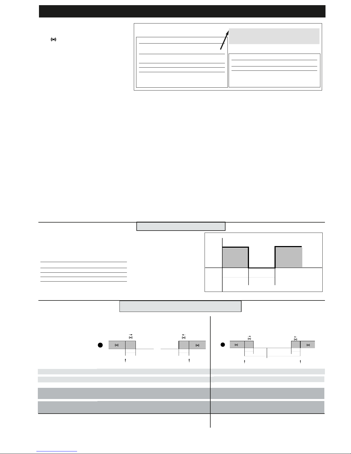
RS232 (to PC)
RS485
BusAdapter
PCInterface
TTL
PC with
Televis package
230V
N
L
230V
N
L
The Televis remote control systems can be connected using the TTL serial port
(the TTL- RS 485 BUS ADAPTER 130 or 150 interface module must be used).
To configure the instrument to do this, you need to access the folder with the
“Add” label and use the “dEA” and “FAA” parameters.
TELEVIS SYSTEM
BUSAdapter130/150
TTL - RS-485 serial interface on DIN rail
for connecting device and a RS-485
network designed for connection to
Televis monitoring system.
PCInterface1100
RS-232/RS-485 serial interface for connecting a PC and a series of instruments in an RS-485 network. The
device needs the BlueCard activation
module supplied with the Eliwell software package licence to be plugged in.
Page 5

DIFFERENTIAL ADJUSTMENT
DIFFERENTIAL ADJUSTMENT
For this type of adjustment, set:
•folder CnF, parameter H42=y indicating
the presence of probe Pb2;
•folder CnF, parameter H03=1 indicating
the type of adjustment (=1, adjustment
according to Pb1-Pb2 difference compared
with set point;
On the basis of these settings, the new
adjustment value is calculated according
to the difference between the values read
by the two probes “diff”=Pb1-Pb2.
If the difference is positive (Pb1> Pb2) or
negative (Pb2>Pb1) but lower or equal to
the value of the set point (SP1>”diff”, or
SP1=”diff”) the output set “for heating”
will be activated.
If the difference is positive (Pb1> Pb2) but
higher than the value of the set point
(SP1>”diff”) the output set “for cooling”
will be activated.
-->Adjustment varies according to parameter H01 that determines the link between
the outputs. See diagram on right.
SETPOINT=OFFSET ADJUSTMENT
SETPOINT=OFFSET ADJUSTMENT
compared with Pb2.
compared with Pb2.
For this type of adjustment, set:
•folder CnF, parameter H42=y indicating
the presence of probe Pb2;
•folder CnF, parameter H03=2 indicating
the type of adjustment (H03=2, adjustment of set point calculated as offset from
probe Pb2;
On the basis of these settings, the new
adjustment value “SE= effective set point”
is calculated according to the sum of the
set point offset (see parameter SP1) and
the value read by probe Pb2 within the
new setting limits defined by parameters LLS and HLS.
The control input is always determined by
Pb1.
-->Adjustment varies according to parameter H01 that determines the link between
the outputs. See diagram on right.
IC 915 LX 5/10
DIFFERENTIAL and SET POINT OFFSET ADJUSTMENT
HC1
H*
H*
-
H* maximum set point controller with differential
dF1 negative
C** minimum set point controller with differential
dF2 positive
NOTE:
•for 1 and 2 examples with HC1=H e HC2=C;
•for 3 HC1 and HC2 settings are ignored
HC2
C**
C**
-
H01
0
1
2
type of regulation
independent set points
dependent set points
Neutral Area (or window)
SP1
SP1-dF1
dF1
Off
On
SP2+dF2
SP2
dF2
Off
On
HC1=H
H01=in
HC2=C
differential adjustment
diagrams
SP1
SP1-dF1
dF1
Off
On
SP1+SP2+dF2
SP1+SP2
dF2
Off
On
HC1=H
H01=di
HC2=C
SP1-db2+dF2
SP1-db2
dF2
Off
On
SP1+db1
SP1+db1-dF1
dF1
On
OUTPUT 2
OUTPUT 1
SP1
db2
db1
independent outputs. The two
outputs regulate as though
they are completely independent
dependent outputs. The set
point 2 SP2 regulates according to SP1
outputs with Neutral Zone
adjustment
(or window).
NOTE: if dF1 and dF2 are both
=0 the outputs are deactivated when SP1 is reached
1
2
3
SP1
+pb2
SP1
+pb2
-dF1
dF1
Off
On
SP2
+pb2
+dF2
SP2
+pb2
dF2
Off
On
HC1=H
HC2=C
Setpoint=offset adjustment
compared with Pb2 diagrams.
SP1
+pb2
SP1+pb2
-dF1
dF1
Off
On
SP1
+pb2
+SP2
+dF2
SP1
+pb2
+SP2
dF2
Off
On
HC1=H
HC2=C
SP1
+pb2
-db2+dF2
SP1
+pb2
-db2
dF2
Off
On
SP1+pb2
+db1
SP1+pb2
+db1-dF1
dF1
On
OUTPUT 2
OUTPUT 1
SP1
+pb2
db2
db1
independent outputs. The two
outputs are adjusted as if they
were completely independentexcept for the
Pb2 analogue
input for both
dependent outputs. The set
point 2 SP2 is adjusted
according to SP1 and Pb2
outputs with Neutral Zone
adjustment
(or window).
NOTE: if dF1 and dF2 are both
=0 the outputs are deactivated when SP1 is reached
1
2
3
H01=0
H01=1
H01=2
H01=0
H01=1
H01=2
Page 6
IC 915 LX 6/10
The alarm condition is always signalled
by a buzzer (if present) and the alarm
icon
LED. The alarm signals from the
• control probe that measures values outside the nominal reading range
• control probe faulty/shorted/open
probe appears directly on the instrument
display as E1.
Note: to prevent false alarms, the error
condition must persist for more than 10
seconds.
An error condition in probe 1 (regulation)
leads to:
• E1 code appears on display
• the controller being activated as indicated by the “On1(On2)” and “OF1(OF2)”
parameters if programmed for the duty
cycle or... (see DUTY CYCLE diagram)
MAXIMUM AND MINIMUM TEMPERATURE ALARM (SEE PAR. H04)
If an alarm condition occurs and alarm
exclusion times are not in progress (see
alarm exclusion parameters), the alarm
icon lights up permanently and the relay
that is configured as an alarm is activated.
This type of alarm does not affect the
regulating in progress.
Alarms are considered as absolute
(default) values or as values related to the
Set point (the distance from the Set point
itself) and based on the Att parameter. If
the alarms are relative (Att=1), the parameter HA1(2) is set to positive values and
LA1(2) to negative values.
This alarm condition can be viewed in the
folder “AL” with labels “AH1-AL1”.
EXTERNAL ALARM
The device can also control an external
alarm, i.e. from a digital input. If the digital input is enabled, the alarm control is
activated by programming and remains
enabled until the next time the digital
input is deactivated. The alarm is signalled
by turning on the fixed alarm icon, activating the relay configured as alarm and
deactivating compressor, defrost and fan
controls (if specified by the “H11=5” parameter). This alarm condition can be displayed in the “AL” folder using the “EA”
label. The relay can be silenced; even if
the alarm icon starts blinking, the controllers remain locked until the next time
the digital input is deactivated.
OPEN DOOR ALARM
If a door is open, the Open Door alarm is
signalled in response to a delay defined
by the tdO parameter.
The alarm is signalled by the flashing
alarm icon. This alarm condition can be
viewed in the “AL” folder with the label
“Opd”.
DIAGNOSTICS
DISPLAY
E1
E2
If simultaneous, they will be shown on the display
alternately every 2 seconds
FAULT
Faulty probe 1 (thermostat control)
Faulty probe 2 (evaporator)
Table of faulty probes
DISPLAY
AH1**
AL1**
EA
Opd
Press any button to silence the alarm. The LED will
start to blink.
ALARM
High temperature alarm (referring to
probe Pb1/Pb2 based on par. H04)
Low temperature alarm (referring to
probe Pb1/Pb2 based on par. H04)
External alarm
Door Open Alarm
Alarm table
Minimum temperature alarm
Maximum temperature alarm
LAL
AFd
HAL
AFd
1
set+ LAL
AFd
Off
set+HAL
AFd
set
2
Temperature lower than or equal to LA1(2) (LA1(2) with sign)
Temperature lower than or equal to set point +LA1(2) positive only)
Temperature greater than or equal to set point +HA1(2) (HA1(2) positive only)
Temperature greater than or equal to HA1(2) (HA1(2) with sign)
Maximum temperature alarm
back swing
Minimum temperature alarm
back swing
Temperature greater than or equal to LA1(2)+AFd Temperature greater than or equal to set point + LA1(2) + AFd
set point -|LA1(2)|+AFd
Temperature lower than or equal to set point+HAL-AFd
Temperature lower than or equal to HA1(2)-AFd
Temperature expressed as an absolute value (par “Att0)
Abs(olute)
Temperature expressed in relation to set point
(par “Att”=0) reL(ative)
if Att=reL(ative) LA1(2) must be negative: therefore
set point+LAL<set point because set point+(-|LA1(2)|)=set-|LA1(2)|
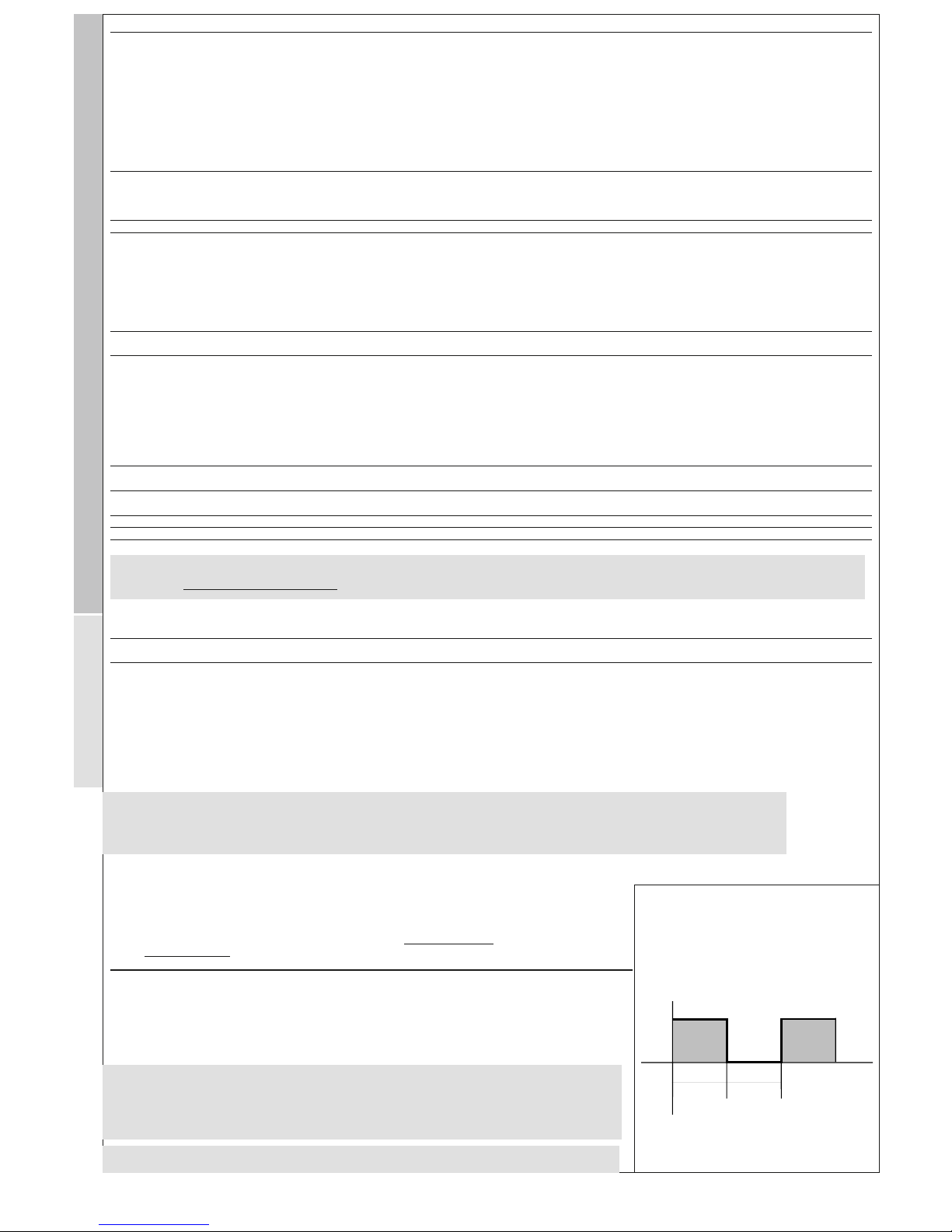
ALARM DIAGRAM HIGH AND LOW TEMPERATURE
OF1(2)
Off
On
OUT
On1(2) On1(2)
An error condition in probe 1
(regulation) leads to:
• E1 code appears on display
• activation of controller as
indicated by the “On1(On2)”
and “OF1(OF2)” parameters if
programmed for the duty cycle
Ont
0
0
>0
>0
OFt
0
>0
0
>0
Compressor output
OFF
OFF
ON
dc
DUTY CYCLE DIAGRAM
On1(2) OF1(2) parameters programmed
for Duty Cycle
**VALUE H04
= 0 —> Pb1-Pb2;
= 1 —> Pb1;
= 2 —> Pb2;
= 3 —> Pb1 and Pb2.
Page 7

PAR.
HC1
OS1
db1
dF1
HS1
LS1
HA1
LA1
dn1
do1
di1
dE1
On1
OF1
HC2
OS2
db2
dF2
HS2
LS2
HA2
LA2
dn2
do2
di2
dE2
On2
OF2
dSi
dSt
Unt
SEn
Sdi
Con
CoF
7/10
DESCRIPTION
CONTROLLER 1 (folder with “rE1” label)
Regulating mode. If set to H, the controller operates in heating mode.
If set to C, the controller operates in cooling mode.
Offset Set point 1
Regulation band 1 See ON-OFF regulation diagram
Relay 1 intervention differential. The load will stop when Set point 1 is
reached (as indicated by the control probe) and will restart at a temperature equal to Set point 1 plus (or minus depending on HC1) the
value of the differential. See ON-OFF reg. diagram
Maximum value for set point 1. By default, it will be set to the maximum value that the probe can reach.
Minimum value for set point 1. By default, it will be set to the minimum value that the probe can reach.
Maximum alarm OUT 1 See Max/Min. Alarm diagram.
Minimum alarm OUT 1 See Max/Min. Alarm diagram.
CONTROLLER 1 PROTECTIONS (folder with “rE1” label)
Start-up delay. The specified time must elapse between the controller
relay start-up request and actual start-up.
Delay after shut-down. The specified time must elapse between shutdown of controller relay and a subsequent start-up.
Delay between start-ups. The specified time must elapse between two
subsequent start-ups of the controller.
Shut-down delay. The specified time must elapse between the controller relay shut-down request and actual shut-down.
NOTE: for parameters dn1, do1, di1, dE1 0= not active
Controller start-up time if probe is faulty. If set to “1” with Oft at “0”
the controller is always on whereas if Oft >0 it operates in duty cycle
mode.
See Duty Cycle diagram
Controller shut-down time if probe is faulty. If set to “1” with Oft at
“0” the controller is always off whereas if Oft
>0 it operates in duty cycle mode.
See Duty Cycle diagram
CONTROLLER 2 (folder with “rE2” label)
Regulating mode. If set to H, the controller operates in heating mode.
If set to C, the controller operates in cooling mode.
Offset Set point 2
Regulation band 2 See ON-OFF regulation diagram
Relay 2 intervention differential. The load will stop when the Set point
is reached (as indicated by the control probe) and will restart at a
temperature equal to Set point 2 plus (or minus depending on HC2)
the value of the differential. See ON-OFF reg. diagram
Maximum value for set point 2. By default, it will be set to the maximum value that the probe can reach.
Minimum value for set point 2. By default, it will be set to the minimum value that the probe can reach.
Maximum alarm OUT 2 SEE ALARM DIAGRAM HIGH AND LOW T.
minimum alarm OUT 2 SEE ALARM DIAGRAM HIGH AND LOW T.
CONTROLLER 2 PROTECTIONS (folder with “rE2” label)
Delay in start-up of controller 2. See dn1
Delay after shut-down. The specified time must elapse between shutdown of controller 2 relay and a subsequent start-up.
Delay between start-ups. The specified time must elapse between two
subsequent start-ups of controller 2.
Delay in shut-down of controller 2. The specified time must elapse
between the controller relay shut-down request and actual shut-down.
NOTE: for parameters dn2, do2, di2, dE2 0= not active
Controller start-up time if probe is faulty. If set to “1” with Oft at “0”
the controller is always on whereas if Oft >0 it operates in duty cycle
mode.
See Duty Cycle diagram
Controller shut-down time if probe is faulty. If set to “1” with Oft at
“0” the controller is always off whereas if Oft >0 it operates in duty
cycle mode. See Duty Cycle diagram
SOFT START (folder with “SFt” label)
dynamic Step increment (Step Value). Value (in degrees)of each of
subsequent increases (dynamic) of adjustment point. 0=disables SOFT
START function.
dynamic Step time (Step Duration). Time between two subsequent
increases (dynamic) of set point
Unit of measurement (hours, minutes, seconds)
Enabled outputs. Establishes which outputs the function must be
enabled on: 0 = disabled; 1 = OUT 1; 2 = OUT 2; 3 = OUT 1 & 2;
Function reinsertion threshold. Establishes the threshold beyond which
the SOFT START function is automatically re-inserted
PERIODIC CYCLE (folder with “cLc” label)
Output ON time.
Output OFF time.
Tab. 1 Table of parameters
DEFAULT*
C
0
1
1
140
-50
140
-50
1
0
0
0
0
1
C
0
1
1
140
-50
140
-50
1
0
0
0
0
1
0
0
1
1
0
0
0
RANGE
H/C
-30.0...30.0
0...30.0
0.0...30.0
LS1..HdL
LdL..HS1
LA1…350.0
-99.9…HA1
0...250
0...250
0...250
0...250
0...250
0...250
H/C
-30.0...30.0
0...30.0
0.0...30.0
LS2..HdL
LdL..HS2
LA2…350.0
-99.9…HA2
0...250
0...250
0...250
0...250
0...250
0...250
0…25.0
(0...twenty-five.0)
0…250
0/1/2
0/1/2/3
0…30.0
0…250
0…250
VALUE**
U.M.
flag
°C/°F
°C/°F
°C/°F
°C/°F
°C/°F
°C/°F
°C/°F
°C/°F
sec
min
min
sec
min
min
flag
°C/°F
°C/°F
°C/°F
°C/°F
°C/°F
°C/°F
sec
min
min
sec
min
min
°C/°F
H/m/sec
H/m/sec
num
°C/°F
min
min
LEVEL***
1
2
1
1
1
1
1
1
1
1
1
1
1
1
1
2
1
1
1
1
1
1
1
1
1
1
1
1
2
2
2
2
2
2
2
IC 915 LX
SP1: Control SetPoint 1, range LS1...HS1
SP2: Control SetPoint 2, range LS2...HS2
***NOTE: At level 1 the folders will only display all the level 1 parameters. At level 2 the folders will only
display all the level 2 parameters.
rE1
re2
SFt
CLc
Page 8

PAR.
Att
AFd
PAO (!)
(2)
SAO
tAO (2)
AOP
dEA (!)
FAA (!)
LOC
PA1
PA2****
ndt
CA1
CA2
CAI
LdL
HdL
LLS
HLS
dro
ddd
H00(1)(!)
H01
H02
H03
H04
H05
H06
H08
H10
IC 915 LX 8/10
DESCRIPTION
ALARMS (folder with “AL” label)
Alarm type. Parameter “HAL” and “LAL” modes, as absolute temperature values or as differential compared to the Set point. 0 = absolute
value; 1 = relative value.
Alarm Fan differential. Alarm differential. Power-on Alarm Override.
Alarm exclusion time after instrument start-up following a power failure.
Set point Alarm Override. Alarm exclusion time after reaching set
point. 0 = disabled. If >0, an alarm will be generated if the set point
is not reached after the time (in hours) set by this parameter.
temperature Alarm Override. Temperature alarm signal delay time.
Alarm Output Polarity. Polarity of alarm output.
0 = alarm active and output disabled; 1 = alarm active and output
enabled.
COMMUNICATION (folder with “Add” label)
dEvice Address. dEA = device address in family (valid values from 0 to
14)
FAmily Address. FAA = device family (valid values from 0 to 14)
The pair of values FAA and dEA represents the device network
address and is indicated as “FF.DD” (where FF=FAA and DD=dEA).
DISPLAY (folder with “diS” label)
Keyboard locked (set point and buttons). However, you can still
access the parameter programming menu and modify parameters
including the status of this parameter to allow keyboard unlocking.
y = yes; n = no.
Password 1. When enabled (value is not 0) it represents the access
button to level 1 parameters.
Password 2. When enabled (value is not 0) it represents the access
button to level 2 parameters.
number display type. Display with decimal point.
y = yes; n = no.
Calibration 1. Positive or negative temperature value that is added to
the value read by control probe (probe 1) before being displayed or
used for control.
Calibration 1. Positive or negative temperature value that is added to
the value read by control probe (probe 2) before being displayed or
used for control.
CAlibration Intervention. Intervention of offset on display, thermostat
control or both.
0 = only modifies the temperature displayed;
1 = adds to the temperature used by controllers, not the temperature displayed that remains unchanged;
2 = adds to temperature displayed that is also used by controllers.
Low display Label. Minimum value the instrument is able to display.
High display Label. Maximum value the instrument is able to display.
Low Limit Setpoint. Minimum value the instrument is able to display.
High Limit Setpoint. Maximum value the instrument is able to display.
Select °C or °F to display temperature read by probe.
N. B.: switching from °C to °F DOES NOT modify set points, differentials, etc. (for example set point=10°C becomes 10°F).
Selection of the value type to be displayed.
0 = Set point;
1 = probe 1 (Pb1);
2 = probe 2 (Pb2);
CONFIGURATION (folder with “CnF” label)
For selection of probe type, PTC or NTC.
Output link. 0 = independent; 1 = dependent; 2 = Neutral Zone (or
window)
Button activation time if buttons are configured for a second function.
For the ESC, Up and DOWN buttons configured for a second function (defrost, aux, etc) the time for rapid enabling is set. Aux is an
exception and has a set time of 1 second
Adjustment type SEE
DIFFERENTIAL AND SETPOINT OFFSET
ADJUSTMENT
0 = standard adjustment;
1 = adjustment according to difference between Pb1-Pb2 and set point;
2 = set point adjustment calculated as offset from probe Pb2 Setting
value on basis of which temperature alarms will be signalled SEE
ALARM DIAGRAM HIGH AND LOW TEMP.:
0 = Pb1-Pb2;
1 = Pb1;
2 = Pb2;
3 = Pb1 e Pb2.
Window filter. -2=very fast; -1=fast; 0=normal; 1=slow; 2=very slow
button/aux input/door switch light active when instrument is off (but
powered)
Stand-by operating mode.. 0= only display switched off; 1= display
on and controllers locked; 2= display off and controllers locked;
Output delay from power-on. Attention! If = 0 is not active; if ≠ 0
the output will not be activated before this time has expired
DEFAULT*
Abs
2
0
0
0
nc/no
0
0
n
0
0
n
0
0
2
-50
140
-50
140
°C
1
PtC/ntC*
0
5
0
1
0
y
2
0
RANGE
Abs/reL
1.0…50.0
0…10
0…10
0…250
nc/no
0…14
0…14
n/y
0...250
0...250
n/y
-30.0...30.0
-30.0...30.0
0/1/2
-67.0…HdL
LdL…302
LdL…HLS
LLS…HdL
°C/°F
0/1/2
PtC/ntC
0/1/2
0...15
0/1/2
0/1/2/3
-2/+1/0/1/2
n/y
0/1/2
0...250
VALUE**
U.M.
flag
°C/°F
hours
hours
min
flag
num
num
flag
num
num
flag
°C/°F
°C/°F
num
°C/°F
°C/°F
°C/°F
°C/°F
flag
num
flag
num
sec
°C/°F
num
num
flag
num
min
LEVEL***
1
2
1
1
1
2
1
1
1
1
2
1
1
1
2
2
2
1
1
1
2
1
1
2
1
1
2
2
2
1
***NOTE: At level 1 the folders will only display all the level 1 parameters. At level 2 the folders will only
display all the level 2 parameters.
AL
Add
diS
CnF
Page 9
IC 915 LX 9/10
PAR.
H11
H13
H14
H21 (!)
H22 (!)
H31 (!)
H32 (!)
H33 (!)
H42
rEL
tAb
UL
dL
Fr
N.B.: if “Fr” parameter (copy card formatting) is used, the data entered in the card will be permanently lost. This operation cannot be undone. After the
operation with the Copy Card the controller must be switched off and then switched back on
(1) Check the NTC/PTC default probe type installed (see label)
(2) Refers exclusively to high and low temperature alarms
* DEFAULT column: for parameters HC1, HS1, LS1, DF1, H00 the default value depends on the model.
** VALUE column: to be compiled manually with any custom settings (if different from default value).
*** LEVEL column: indicates the visibility level of parameters accessed using a PASSWORD (see relevant paragraph)
**** PA2 is visible (or will be requested, if specified) at level 1 in the CnF folder
and can be set (modified) at
level 2 in the diS folder
(!) WARNING!
• If one or more parameters marked with (!) are modified, the controller must be switched off after the modification and then switched back on
•NOTE: We strongly recommend that you switch the instrument off and on again each time parameter configuration
is changed in order to prevent malfunctioning of the configuration and/or ongoing timings.
DESCRIPTION
Configuration of digital inputs
0 = disabled;
1 = SOFT START;
2 = Set point Offset;
3 = outputs shut down;
4 = periodic cycle;
5 = auxiliary output;
6 = stand-by
7 = maintenance request
8 = external alarm
9 = external alarm to lock controllers
Polarity and priority Digital Input no= normally open/ nc= normally
closed / noP= normally open with polarity / ncP= normally closed with
polarity
Enabling delay Digital Input
Configurability digital output 1 (OUT1)
0 = disabled;
1 = on-off
2 = not used;
3 = alarm;
4 = cyclic
5 = aux/light
6 = stand-by
Configurability digital output 2. (OUT2)
Same as H21.
UP button configurability.
0 = disabled;
1 = SOFT START;
2 = Set point Offset;
3 = outputs shut down;
4 = periodic cycle;
5 = auxiliary output (aux);
6 = stand-by;
7 = maintenance request
DOWN button configurability.
Same as H31.
ESC button configurability.
Same as H31.
Presence of probe 2. n= not present; y= present.
Device version. Read only parameter.
Reserved. Read only parameter.
COPY CARD (folder with “Fpr” label)
UpLoad: transfer of programming parameters from instrument to Copy
Card.
downLoad: transfer of programming parameters from Copy Card to
instrument.
Format. Cancels all data entered in the copy card.
DEFAULT*
0
no
0
1
1
0
0
0
y
/
/
/
/
/
RANGE
0…9
no/nc/noP/ncP
0…250
0…6
0…6
0…7
0…7
0…7
n/y
/
/
/
/
/
VALUE* LEVEL***
2
2
2
2
2
2
2
2
2
1
1
1
1
1
U.M.
num
num
min
num
num
num
num
num
flag
/
/
/
/
/
FUNCTIONS (folder with “FnC” label)The FnC folder (last folder visible from the Programming Menu) contains several functions that are activated using the “set” button
SEE FUNCTIONS paragraph
label PA2
In the CnF folder you can access all level 2 parameters from label PA2 by pressing the “set” button
SEE paragraph 2) Displaying level 2 parameters
(°) The mathematical conversion for temperature is °F=(9/5)* °C+32. For example: 32°F=0°C; 50°F=10°C.
dro parameter: when changing from °C to °F or vice versa the mathematical conversion is NOT performed
and the values are NOT modified.
All the temperature values set will therefore need reviewing. e.g. with a set point set at 10°C, the set point
will become 10°F and not 50°F when changing the value to °F (according to conversion table)
***NOTE: At level 1 the folders will only display all the level 1 parameters. At level 2 the folders will only
display all the level 2 parameters.
Cof
Off
On
OUT
Con Con
Periodic Cycle Diagram
CnF
Fpr
Page 10

IC 915 LX 10/10
Wiring Diagram
TERMINALS (12V and 230V versions)
1 - 2 N.O. controller relay 1 (OUT1)
1 - 3 N.C. controller relay 1 (OUT1)
4 - 5 N.O. controller relay 2 (OUT2)
6 - 7 Power supply 1.5 VA max. (12V version)
Power supply 3 VA max. (230V version)
8 - 10 Probe input 1 (control*) Pb1
8 - 9 Probe input 2 (control**) Pb2
8 - 11 Digital Input (D.I.)
A TTL input for Copy Card and connection to
TelevisSystem
NOTE:
* used for differential adjustment
** used for offset and set point differential adjustment
• Default load settings
• for relay capacity, see instrument label.
The diagram only shows 12 and 230V power supplies
and 8(3)A 250V capacity relays
IC 915 LX - 12 V
A
6 7
1 2 3 4 5
D.I.
OUT1 OUT2
10
8 9
11
Supply
Pb2
Pb1
IC 915 LX - 230 V
A
6 7
1 2 3 4 5
D.I.
OUT1 OUT2
10
8 9
11
Supply
Pb2
Pb1
Eliwell & Controlli s.r.l.
Via dell'Industria, 15 Zona Industriale Paludi
32010 Pieve d'Alpago (BL) ITALY
Telephone +39 0437 986111
Facsimile +39 0437 989066
Internet http://www.eliwell.it
Technical Customer Support:
Email: techsuppeliwell@invensys.com
Telephone +39 0437 986300
Climate Controls Europe
An Invensys Company
12/2004 eng
cod. 9IS23071
CONDITIONS OF USE
PERMITTED USE
For safety reasons the instrument must be installed
and used in accordance with the instructions supplied.
Users must not be able to access parts with dangerous voltage levels under normal operating conditions.
The device must be suitably protected from water
and dust according to the specific application and
only be accessible using special tools (except for the
front keypad).
The device is ideally suited for household use and/or
similar use in the refrigeration sector and has been
tested with regard to safety in accordance with the
European harmonized reference standards. It is classified as follows:
• as an automatic electronic control device to be
independently mounted as regards its construction;
• as a 1 B type operated control device as regards its
automatic operating features;
• as a Class A device as regards the category and
structure of the software.
UNPERMITTED USE
The use of the unit for applications other than those
described above is forbidden.
It should be noted that the relay contacts supplied
with the device are functional and therefore exposed
to potential faults. Any protection devices required to
comply with product requirements or dictated by
common sense due to obvious safety reasons should
be installed externally.
RESPONSIBILITY AND RESIDUAL RISKS
Eliwell & Controlli s.r.l. shall not be liable for any dam-
ages deriving from:
- installation/use other than that prescribed and, in
particular, which does not comply with the safety standards specified in the regulations and/or those given
herein;
- use on equipment that does not guarantee adequate
protection against electric shock, water or dust when
assembled.
- use on equipment that allows dangerous parts to be
accessed without the use of tools;
- tampering with and/or alteration of the product;
- use on equipment that does not comply with the
standards and regulations in force.
DISCLAIMER
This document is the exclusive property of Eliwell &
Controlli s.r.l. and cannot be reproduced and circulated unless expressly authorized by Eliwell &
Controlli s.r.l..
Although Eliwell & Controlli s.r.l. has taken all possible measures to guarantee the accuracy of this document, it declines any responsibility for any damage
arising out of its use.
The same applies to any person or company involved
in preparing and writing this manual. Eliwell &
Controlli s.r.l. reserves the right to make any changes
or improvements without prior notice and at any
time.
CONDITIONS OF USE
Permitted Use
For safety reasons the instrument must be installed and
used in accordance with the instructions supplied.
Users must not be able to access parts with dangerous
voltage levels under normal operating conditions.
The device must be suitably protected from water and
dust according to the specific application and only be
accessible using special tools (except for the front keypad).
The device is ideally suited for household use and/or similar use in the refrigeration sector and has been tested
with regard to safety in accordance with the European
harmonized reference standards. It is classified as follows:
• as an automatic electronic control device to be independently mounted as regards its construction;
• as a 1 B type operated control device as regards its
automatic operating features;
• as a Class A device as regards the category and structure of the software. Unpermitted use
The use of the unit for applications other than those
described is forbidden.
It should be noted that the relay contacts supplied with
the device are functional and therefore exposed to
potential faults.
Any protection devices required to comply with product
requirements or dictated by common sense due to obvious safety reasons should be installed externally.
 Loading...