

Page 1
THE USER INTERFACE
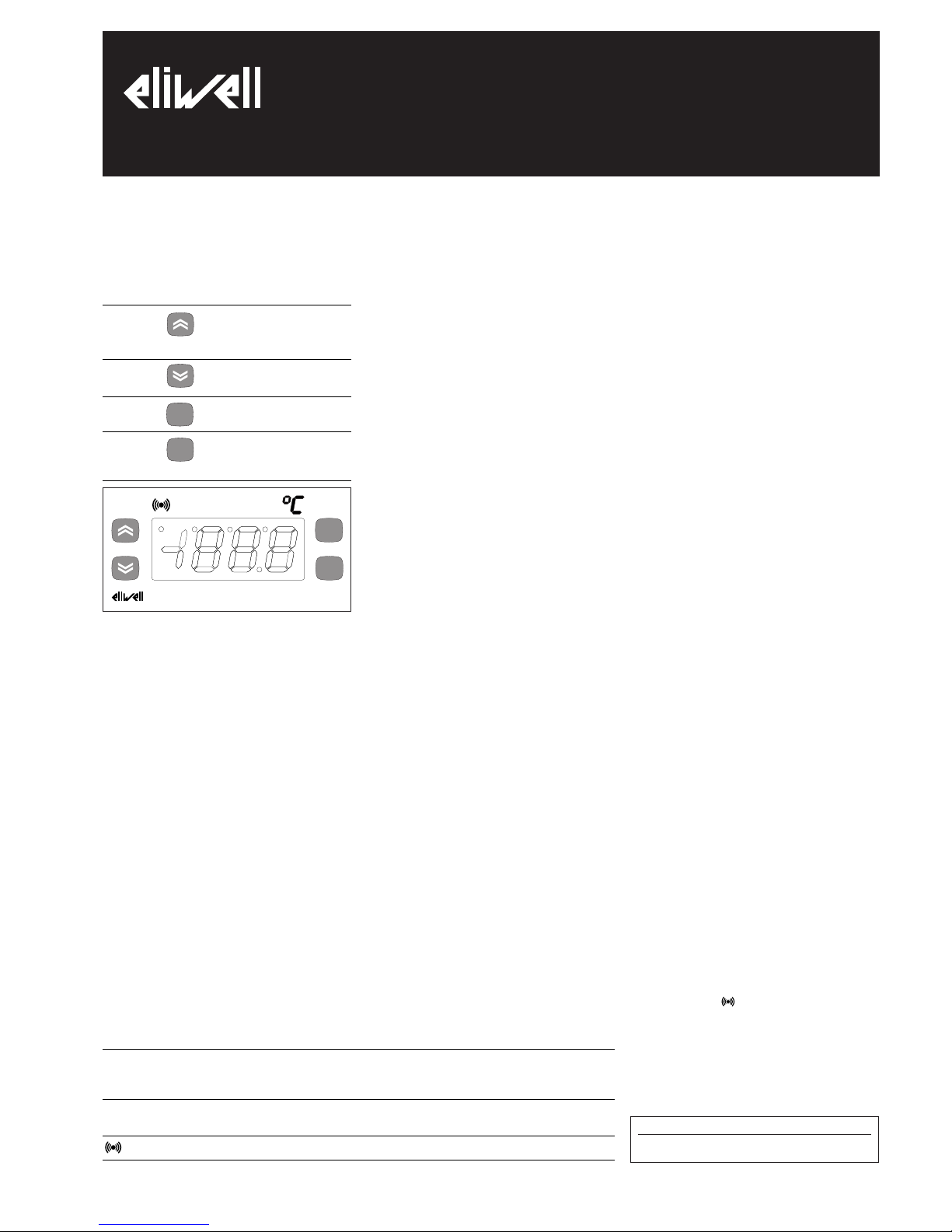
The user has a display and four keys for
controlling status and programming of the
instrument.
KEYS AND MENUS
UP key Scrolls through the menu items
Increases the values
DOWN key Scrolls through the menu items
Decreases the values
fnc key ESC function (exit)
set key Accesses the setpoint
Accesses the menus
Confirms the commands
At start-up the instrument performs a
Lamp Test; for few seconds the display and
the leds blink, in order to verify their
integrity and correct operation. The instrument has two main menus: the “Machine
Status” and “Programming” menu.
ACCESSING AND USING MENUS
Resources are arranged in a menu, which
can be accessed by pressing and quickly
releasing the “set” key (“Machine Status”
menu) or by holding down the “set” key
for more than 5 seconds (“Programming”
menu).
To access the contents of each folder, indicated by the relevant label, just press the
“set” key once.
You can now scroll through the contents
of each folder, modify it or use its functions.
If you do not use the keyboard for over 15
seconds (time-out) or if you press the
“fnc” key once, the last value shown on
the display is confirmed and you return to
the previous screen mask.
MACHINE STATUS MENU
(See Machine Status Menu)
To access the “Machine Status” menu Press
and quickly release the “set” key.
If alarms are not present, the label “SEt”
appears. By using the “UP” and “DOWN”
keys you can scroll through the other folders in the menu:
-Pb1: probe 1 value folder;
-SEt: Setpoint setting folder.
Set Setting
Access the “Machine Status” menu by
pressing and quickly releasing the “set”
key. The label of the “SEt” folder appears.
To display the Setpoint value press the
“set” key again.
The value appears on the display.
To change the Setpoint value, use the “UP”
and “DOWN” keys within 15 seconds.
If the parameter is LOC = y the Setpoint
cannot be changed.
Displaying Probes
By pressing the “set” key when the appropriate label appears, the value of the
probe associated to it is displayed.
PROGRAMMING MENU
(See Programming Menu)
To enter the “Programming” menu, press
the “set” key for more than 5 seconds.
If specified, the access PASSWORD will be
requested, (parameter “PA1”), and (if the
password is correct) the label of the first
folder will follow.
To scroll through the other folders, use
the “UP” and “DOWN” keys; the folders
contain the level 1 parameters.
If the password is wrong, the display will
show the PA1 label again.
To enter the folder, press “set”. The label
of the first visible parameter appears. To
scroll through the other parameters, use
the “UP” and “DOWN” keys; to change the
parameter, press and release “set”, then
set the desired value using the “UP” and
“DOWN” keys, and confirm with the “set”
key to move to the next parameter.
PLEASE NOTE: It is suggested to switch-off
and switch-on again the instrument everytime it is changed the configuration of the
parameters: this prevents malfunctioning
on regulation and delay time occuring.
PASSWORD
The password “PA1”allow access to level 1
parameters. In the standard configuration
passwords are not present.
To enable them (value≠0) and assign them
the desired value, access the
“Programming” menu, within the folder
with the “diS” label.
If password is enabled, it will be requested at the entrance of the “Programming”
menu (see the “Programming Menu“ section);
COPY CARD
The Copy Card is an accessory connected
to the TTL serial port which allows programming quickly the instrument parameters. The operation is performed as follows:
Upload
This operation loads the programming
parameters from the instrument.
Download
This operation downloads to the instrument the programming parameters.
The operations are performed accessing
the folder identified by the “FPr” label and
selecting, according to the case, “UL” or
“dL” commands; the operation is confirmed by pressing the “set” key. If the
operation is successful an “y” is displayed,
on the contrary, if it fails a “n” will be displayed.
NOTE:
• UPLOAD: instrument --> Copy Card
• DOWNLOAD: Copy Card --> instrument.
KEYBOARD LOCKING
The instrument includes a facility for disabling the keyboard, by programming the
“Loc” parameter (see folder with “Dis”
label). If the keyboard is locked, you can
still access the programming menu by
pressing the “set” key.
The Setpoint can also be viewed.
DIAGNOSTICS
The alarm condition is always signalled by
the buzzer (if present) and by the led of
the alarm icon
The alarm signal produced by a faulty
thermostat probe (probe 1) is shown as E1
on the instrument display.
IC 902
electronic thermostat with single output
fnc
set
LED
Position Associated function Status
out Relay 1 ON for relay ON, flashing for delay, disabled protection
or activation
Alarm ON for an active alarm
°C Setpoint ON when setting the Setpoint
set
f nc
IC902
out
DISPLAY
E1
ERROR
Thermostat probe fault
Error table
Page 2

When the sensor detects an error condition:
• the code E1 is displayed
• the regulator is activated as indicated by
the "On" and "Off" parameters if programmed for the duty cycle or:
INSTALLATION
The instrument is designed for flush panel
mounting. Insert the unit through a
71x29 mm panel cut-out and affix with the
U-bracket supplied.
Select a location which will not be subject
to high humidity or condensation and
allow some ventilation to provide cooling
to the instrument.
ELECTRICAL
CONNECTIONS
Attention! Never work on electrical connections when the machine is switched on.
The instrument is equipped with screw terminal boards for connection of electrical
cables with a diameter of 2.5 mm
2
(one
conductor only per terminal for power
connections). For the capacity of the terminals, see the label on the instrument.
Relay outputs are voltage free. Do not
exceed the maximum permissible current
– in case of higher loads, use a contactor
of adequate power. Make sure that the
supplied voltage matches the values specified for the instrument.
In the versions supplied on 12V, the power
supply must be provided via a safety transformer protected by a 250 mA delayed
fuse. The probes do not have any insertion
polarity and can be lengthened by using a
normal bipolar cable (note that if the
probes are lengthened, this will affect the
behaviour of the instrument in terms of
EMC electro-magnetic compatibility –
wiring must be done with great care).
We advise you to keep the probe and supply cables well away from the power
cables.
CONDITIONS OF USE
PERMITTED USE
For safety reasons the instrument must be
installed and used according to the
instruction provided and in particular,
under normal conditions, parts bearing
dangerous voltage levels must not be
accessible.
The device must be adequately protected
from water and dust as per the application
and must also only be accessible via the
use of tools (with the exception of the
frontlet).
The device is ideally suited for use on
household appliances and/or similar refrigeration equipment and has been tested
with regard to the aspects concerning
European reference standards on safety. It
is classified as follows:
• according to its manufacture: as an automatic electronic control device to be
incorporated by independent mounting;
• according to its automatic operating features: as a 1 B-type operated control type;
• as a Class A device in relation to the category and structure of the software
UNPERMITTED USE
Any other use other than that permitted is
de facto prohibited. It should be noted
that the relay contacts provided are of a
practical type and therefore subject to
fault. Any protection devices required by
product standards or dictated by common
sense due to obvious safety reasons should
be applied externally.
LIABILITY AND RESIDUAL
RISKS
Invensys Controls Italy S.r.L. shall not be
liable for any damages deriving from:
- installation/use other than that prescribed and, in particular, that which does
not comply with safety standards anticipated by regulations and/or those given herein;
- use on boards which do not guarantee
adequate protection against electric shock,
water or dust under the conditions of
assembly applied;
- use on boards which allow access to dangerous parts without the use of tools;
- tampering with and/or alteration of the
products;
DISCLAIMER
This manual and its contents remain the
sole property of Invensys Controls Italy
s.r.l., and shall not be reproduced or distributed without authorization. Although
great care has been exercised in the
preparation of this document, Invensys
Controls Italy s.r.l., its employees or its
vendors, cannot accept any liability whatsoever connected with its use. Invensys
Controls Italy s.r.l. reserves the right to
make any changes or improvements without prior notice.
TECHNICAL DATA
Frontal panel protection: IP65.
Casing: plastic body in resin type
PC+ABS UL94 V-0, inspection window in
polycarbonate, buttons in thermoplastic
resin.
Dimensions: frontal panel 74x32 mm,
depth 60 mm.
Installation: on panel, with drilling template 71x29 mm (+0.2/–0.1 mm).
Use temperature: –5…55 °C.
Storage temperature.: –30…85 °C.
Use environment humidity: 10…90 % RH
(not condensing).
Storage environment humidity: 10…90% RH
(not condensing).
Viewing range: –50…140 °C on 3 digit (and
a half) + mark display.
Analogue inputs: one PTC or NTC input
(selectable through parameter).
Serial: TTL for connection to Copy Card.
Digital outputs: one relay output, SPDT
8(3)A 250Va relay
Measuring range: from –50 to 140 °C.
Accuracy: 0.5% better than end scale + 1
digit.
Resolution: 0,1°C or 1°C.
Consumption:
• model 230V: 3 VA max.
• model 12V: 1,5 VA max.
Power supply: 12 Va/c ±10% or 230Va
±10% 50/60 Hz.
Warning: check the power supply specified
on the instrument label; for relay and
power supply capacities, contact the Sales
Office).
IC 902 2/4
Ont
0
0
>0
>0
Oft
0
>0
0
>0
Regulator output
OFF
OFF
ON
dc
PLEASE NOTE: The technical data
included in this document, related to
measurement (range, accuracy, resolution, etc.) refer to the instrument
itself, and not to its equipment such as,
for example, sensors.
This means, for example, that sensor(s)
error(s) shall be added to the instrument’s one.
Page 3

PARAMETER
diF
HSE
LSE
HC
Ont (1)
OFt (1)
dOn
dOF
dbi
OdO (!)
LOC
PA1
ndt
CA1
dro
H00 (!)
rEL
tAb
UL
dL
(1) see Duty Cycle Diagram
* DEFAULT column: for HC, H00 parameters default is depending on model; the decimal point is visible when ndt=1
** VALUE column: to be filled manually, with customized settings (if different from the default value).
*** LEVEL column: indicates the level of visibility of parameters accessible by PASSWORD (see the related paragraph)
(!) WARNING!
• If one or more of these parameters highlighted with (!) are modified, teh controlller must be switched off and switched on again to ensure correct operation.
• It is strongly recommended, anyway to switch off and switch on again the controller anytime parameters have been changed to prevent malfunctioning on configuration
and/or ongoing timings
DESCRIPTION
REGULATOR (folder with “CP”)
Relay regulator tripping differential. The regulator stops on reaching the Setpoint value (as indicated by the adjustment probe), and
restarts at temperature value equal to the Setpoint plus the value
of the differential.
Note: the value 0 cannot be assumed.
Maximum possible setpoint value.
Minimum possible setpoint value.
Heat/Cool Mode. If set to H the generic regulator actuates for hot
operation. If set to C the generic regulator actuates for cold operation
REGULATOR PROTECTIVE DEVICES (folder with “CP” label)
Regulator activation time in the event of faulty probe. If set to “1”
with Oft at “0”, the regulator is always on, while for Oft >0,
it functions always in duty cycle mode.
Regulator in disabled state time in the event of a faulty probe. If
set to “1” with Ont at “0”, the regulator is always off, while at Ont
>0, it functions always in duty cycle mode.
Delay time in activating the regulator relay after switch-on of
instrument.
Delay after switch off. The indicated time must elapse between
switch-off of the regulator relay and the successive switch-on.
Delay between switch-ons. The indicated time must elapse between
two successive switch-ons of the regulator.
delay time in activating the outputs after switch-on of the instrument or after a power failure. 0= not active.
DISPLAY (folder with label “diS”)
Keyboard locking. However, you can enter parameter programming,
modify them and change the status of this parameter to unlock the
keyboard.
y = yes (keyboard locked); n = no.
Password 1. When enabled (value other than 0) it constitutes the
access key for level 1 parameters.
number display type. View with decimal point. y = yes; n = no
Calibration 1. Positive or negative temperature value added to the
value read on the adjustment room probe (probe 1) before being
displayed and used for adjustment.
Selection of °C or °F to view the temperature read by the probe.
0 = °C, 1 = °F.
PLEASE NOTE: the switch between °C and °F DO NOT modify
setpoint, differential, etc. (for example set=10°C become
10°F).
CONFIGURATION (folder with label “CnF”)
Probe type selection, PTC or NTC. 0 = PTC; 1 = NTC.
Device version. Read only parameter.
Reserved. Read only parameter.
COPY CARD (folder with label “Fpr”)
UpLoad: transferring parameters from instrument to Copy Card.
downLoad: transferring parameters from Copy Card to instrument.
Tab. 1 Parameter table
DEFAULT*
2.0
140.0
-55.0
H/C*
0
1
0
0
0
0
n
0
n
0
0
0/1*
/
/
/
/
RANGE
0.1...30.0
LSE..302
-55...HSE
H/C
0...250
0...250
0...250
0...250
0...250
0...250
n/y
0...250
n/y
-12.0...12.0
0/1
0/1
/
/
/
/
VALUE**
U.M.
°C/°F
°C/°F
°C/°F
flag
min
min
sec
min
min
min
flag
num
flag
°C/°F
flag
flag
/
/
/
/
IC 902 3/4
LEVEL***
1
1
1
1
1
1
1
1
1
1
1
1
1
1
1
1
1
1
1
1
Pb1
SEt
Pb1 value
SEt value
set
set
set
change
SEt value
press and release
(single press)
Machine Status Menu Diagram
Page 4

IC 902 4/4
WIRING (12 and 230V)
1 - 2 N.C. regulator relay output OUT
1 - 3 N.O. regulator relay output OUT
6 - 7 Power supply • model 230V: 3 VA max.
• model 12V: 1,5 VA max.
8 - 9 Sensor input (thermostat) Pb1
A TTL input for Copy Card
PLEASE NOTE:
•User Default Settings
• for relay capacities check on the instrument label
In the diagram it is shown relays with 8(3) 1/2 hp 250V
capability and 12/230V supply
1 2 3
6 7 8 9
IC 902 - 12 V
A
Supply
Pb1
OUT
1 2 3 6 7
8 9
IC 902 - 230 V
A
Supply
Pb1
OUT
Wiring diagram
Invensys Controls Italy s.r.l
via dell'Industria, 15 Zona Industriale Paludi
32010 Pieve d'Alpago (BL) ITALY
Telephone +39 0437 986111
Facsimile +39 0437 989066
Internet http:/www.climate-eu.invensys.com
4/2003 eng
cod. 9IS42074
OFt
Off
On
OUT
Ont Ont
When the sensor detects an
error condition:
• the code E1 is displayed
• the regulator is activated as
indicated by the "On" and "Off"
parameters if programmed for
the duty cycle or:
Ont
0
0
>0
>0
OFt
0
>0
0
>0
Regulator output
OFF
OFF
ON
dc
Duty Cycle Diagram
CP
set
level 1 par
set
diS
CnF
Fpr
level 1 par
level 1 par
level 1 par
set
set
set
level 1
change
par value
scroll
parameters
set
PA1≠0
set
set PA1 value
press for 5 sec
Programming Menu Diagram
PARAMETERS
folders level 1
CP
diS
CnF
FPr
 Loading...