

Page 1

Panel
Panel Mount Programmable Controller
Installation Manual
EN
Page 2

CONTENTS
1 Introduction ............................................................................................................................................................. 3
1.1 General description ......................................................................................................................................................................... 3
1.1.1 Specifications: ..................................................................................................................................................................................................................................... 4
1.2 Models and Features....................................................................................................................................................................... 4
2 Mechanical Installation ......................................................................................................................................... 5
3 Electrical connections ........................................................................................................................................... 6
3.1 General warnings.............................................................................................................................................................................. 6
3.1.1 Power supply ....................................................................................................................................................................................................................................... 6
3.1.2 Analogue Inputs-Probes ................................................................................................................................................................................................................... 6
3.1.3 Serial connections.............................................................................................................................................................................................................................. 6
3.2 Wiring diagrams................................................................................................................................................................................ 8
3.3 Analogue inputs................................................................................................................................................................................ 9
3.4 Connections..................................................................................................................................................................................... 10
3.4.1 Example: RS485 connection (Field)............................................................................................................................................................................................. 10
3.4.2 CAN connection example (Field) ................................................................................................................................................................................................10
3.4.3 Example: RS485 connection with FREE Smart network......................................................................................................................................................... 11
3.4.4 CANopen network connection example ................................................................................................................................................................................... 12
4 Technical Data....................................................................................................................................................... 14
4.1 General Technical Data................................................................................................................................................................. 14
4.2 I/O features...................................................................................................................................................................................... 14
4.3 Display............................................................................................................................................................................................... 15
4.4 Serials ................................................................................................................................................................................................ 15
4.5 Transformer..................................................................................................................................................................................... 15
4.6 Mechanical dimensions ................................................................................................................................................................ 15
4.7 Permitted use.................................................................................................................................................................................. 15
4.8 Improper Use .................................................................................................................................................................................. 15
4.9 Disclaimer......................................................................................................................................................................................... 15
5 User Interface ........................................................................................................................................................16
5.1 Keys and LEDs ................................................................................................................................................................................. 16
5.2 First power on................................................................................................................................................................................. 17
5.3 DIAGNOSTICS menu...................................................................................................................................................................... 17
5.3.1 BIOS parameters............................................................................................................................................................................................................................... 17
5.3.2 HMI Management ............................................................................................................................................................................................................................18
5.3.3 Probe values ......................................................................................................................................................................................................................................18
Note: for offset programming see the section on Analogue Inputs in the Connections chapter....................................................................................... 18
5.3.3.1 Date and time ........................................................................................................................................................................................................................ 18
5.4 Remote interface............................................................................................................................................................................ 18
5.4.1 Language............................................................................................................................................................................................................................................. 18
5.4.2 ........................................................................................................................................................................................................................................................ 18
5.4.3 HMI sel ................................................................................................................................................................................................................................................ 18
5.4.3.1 COM Setting ........................................................................................................................................................................................................................... 19
5.4.3.2 HMI Management ................................................................................................................................................................................................................. 19
6 Parameters.............................................................................................................................................................. 20
6.1 Table of parameters ......................................................................................................................................................................20
6.1.1 Table of parameters ........................................................................................................................................................................................................................ 20
7 Models and Accessories...................................................................................................................................... 34
7.1 Models .............................................................................................................................................................................................. 34
7.2 Accessories....................................................................................................................................................................................... 35
EN
Invensys Controls
An Invensys Company
Page 3

References
Cross references
Highlighting icons:
1 INTRODUCTION
To allow quick, easy reference, the guide has been designed with the following features:
References column
A column to the left of the text contains references
need quickly and easily.
Cross references:
words in italics are listed in the analytical index along with the page number where they are dealt with in more detail.
All
In the "on-line" (computer) manual, the words in italics are "hyperlinks" (i.e. mouse-clickable links), connecting up the
different parts of the manual and making it "navigable".
Some text passages are marked by icons in the references c
Important! : highlights information of which an incorrect understanding can i
Note / highlight: indicates further information on the subject concerned that the user should take into account.
Tip: a suggestion that could help the user to understand and make better use of the information
:
to subjects discussed in the text to help you locate the information you
olumn, which have the following meanings:
mpact negatively on the
system or result in risk to persons, instruments, data, etc.; users must read and take note of
these sections.
provided.
1.1 General description
The FREE Panel (EVP) is a fully programmable panel mounting solution with LCD display made by Eliwell,
suitable for managing a wide range of H
The EVP can be
FREE Smart or third-party controllers it guarantees high performance in terms of memory, connectivity and user interface
as well as
The EVP is designed for panel mounting, and can al
Programming of the EVP is managed via the FREE Studio development tool, which makes it possible to quickly and
reliably create and customise new programs for all types of application.
The use of several different programming languages in accordance with IEC61131-3 standard (industrial control
programming ), makes it possible to develop new algorithms or entire programmes totally unassisted, which can th
uploaded to FREE Evolution modules via PC, guaranteeing maximum confidentiality with appropriate security.
The EVP can be
manage a local menu created with the FREE Studio User Interface
mana
share network variables (binding)
WEB functionalities
The FREE Panel (EVP) also features WEB functionalities (the FREE Panel product is also designated FREE WEB) offeri
makers of machinery and systems integrators full remote access. Having a web-based connection in machines significantly
reduces support and maintenance costs by minimizing call-out charges. End users also benefit, as they can mo
own systems both locally and from distance, using the easy-to-understand graphics interface of any common browser via
smartphone, tablet or PC.
Main WEB functionalities
Web-based access.
Remote reading and support.
Local and remote system control, including alarms management.
Preventive and predictive maintenance.
Email alarm alerts.
Next generation system interface on PC, tablet and smartphone.
used as a system controller, with gateway functions; used in combination with the FREE Evolution and
straightforward programming, maintenance and servicing.
used to:
ge up to 10 remote menus, created with the FREE Studio User Interface a
respective FREE Evolution devices connected to the network
VAC/R and many other applications, from the simplest to the most complex.
so be wall-mounted using a special backplate, available as an accessory.
en be
nd uploaded from the
ng
nitor their
FREE Panel
3/38
Page 4

1.1.1 Specifications:
FREE Panel EVP 3300/C is equipped with serial CAN, RS485 and
ETHERNET, 3 inputs (1 on-board NTC + 1 remote
configurable NTC/DI +1 remote current/voltage configurable).
FREE Panel EVP 3500/C/R is equipped with serial CAN, RS485 and ETHERNET, 3 i
nputs (1 on-board humidity module + 1
on-board NTC + 1 remote configurable NTC/DI) .
The EVP comes with a built-in 128x64px graphical user terminal.
- - 24V~/c or 48Vc power supply.
1.2 Models and Features
<IMG INFO>
56,65
29,75
1
2
51
- -> See Appendix A - Models and Accessories, and Technical Data section.
FREE Panel
4/38
Page 5
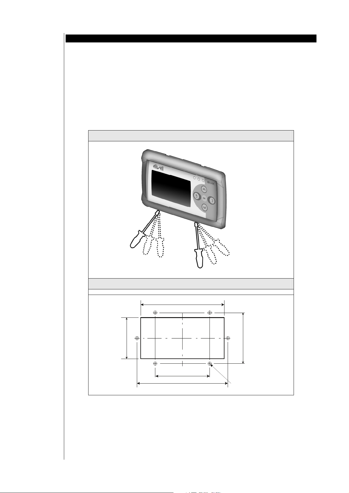
2 MECHANICAL INSTALLATION
IMPORTANT! Always make sure the device is switched OFF before touching connections.
operations must be carried out by qualified personnel.
All
Do not mount devices in extremely damp and/or dirt-laden areas; they are designed for use in places with ordinary or
normal levels of contamination.
Make sure the area near the cooling slots is ventilated.
Mounting the FREE Panel (EVP)
Designed for panel mounting.
Make a 138x68mm hole.
Remove the front panel (figure 1) and make 4 holes in the panel that the controller is to be mounted on (Figure 2, points
A/B/C/D) or two holes (Figure 2, points E/F) of dia. 2.7 mm at the specified spacing (Figure 2).
Insert the device, fixing it with the screws. Press the front of the remote terminal to close.
Figure 1
Cut out EVP
A
E
68
Figure 2
Cut out EVP
138
B
F
84
DC
90
150
(x 6)
2.7
FREE Panel
5/38
Page 6

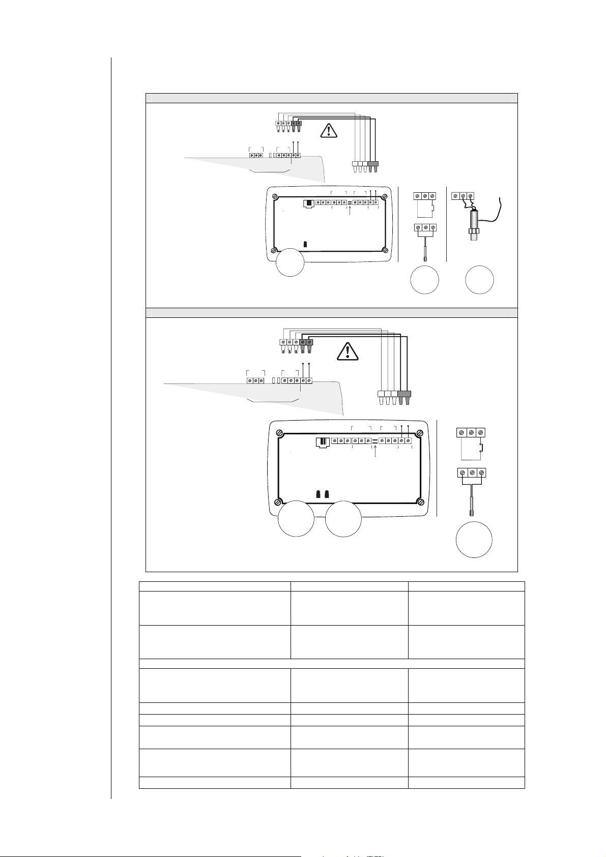
3 ELECTRICAL CONNECTIONS
<IMG INFO>
30,7
43,9
1
2
51
-28,35
-1
<IMG INFO>
30,7
43,9
1
2
51
-28,35
-1
Temperature
obes
pr
Pressure probes
3.1 General warnings
Before proceeding with any operation, make sure the device is connected to a suitable external transformer. T
following rules must be followed when connecting cards to each other and to the application:
Loads that exceed the maximum limits stated in this manual must not be applied to outputs.
When connecting loads, follow the circuit diagrams carefully.
To avoid unwanted couplings, wire all SELV (safety extra voltage) users separately from high voltage
IMPORTANT!
Make sure the appliance is switched off before working on electrical connections.
by skilled personnel. To ensure proper connections,
3.1.1 Power supply
Important!
Make sure that the power supply is
3.1.2 Analogue Inputs-Probes
Probes have no connection polarity and can be exten
probes influences the electromagnetic compatibility (EMC) of the instrument: take great care with the wiring).
Important!
Pressure probes
Signal leads (temperature/pressure probes, digita
routed separately from power cables.
Use probes supplied by Eliwell. Contact Eliwell sales department for parts availability.
users.
Operations must be carried out
comply with the following:
Power supplies other than those specified can seri
ously damage the system.
Select cables of suitable section for the terminals used
Separate the cables of probes and digital inputs from inductive loads and high voltage connections to prevent
y electromagnetic interference. Do not place probe signal leads near other electrical equipment (switches,
an
meters, etc.)
Make connections as s
hort as possible and do not wind them around electrically connected parts.
To avoid electrostatic discharges, do not touch the electronic components on printed circuit boards.
The device must be connected to a suitable transformer th
Technical Data ch
apter.
at complies with the specifications indicated in the
of the correct voltage for the instrument.
ded using a normal two core cable (note that the extension of the
have a specific connection polarity, which must be observed.
l inputs, RS-485/CAN-BUS serials and the electronic supply) must be
he
3.1.3 Serial connections
On-board CAN as
On-board RS485 as
On-board ETHERNET seria
standard
standard
l as standard
Pay special attention when connecting serial lines: Do not connect instruments that communicate using RS485 seria
minals, or CAN instruments to RS485 terminals.
CAN ter
CAN
CAN
TE 1
NO
Use a shielded and "twisted pair" cable with two 0.5mm
2
conductors, plus braiding (ideally Belden cable model
3105A (characteristic impedance 120 Ohms) with PVC sleeve, 2 conductors plus braid, 22 AWG, nominal capacity
between conductors 36pF/m, nominal capacity between conductor and shielding 68pF/m).
Always follow regulations applicable to the routing and connection of cables. Make certain that data transmission
circuits are properly separated from power lines.
For connections
TERM jumpers (available on the terminal strip beside the CAN seria
over longer distances, it is better to end the line with resistors on both ends, inserting the two R
l as the default factory configuration).
NOTE 2
The maximum distance depends on the baud setting.
Kb/s (Kbaud) On-board
CAN
50 Kbaud 1000m
125 Kbaud 500m
250 Kbaud 250m
500 Kbaud 60m
NOTE 3
5-way terminal strip:
3-way ( “GS“, “H and “L”) serial CAN
2-way POWER supply
l to
Page 7

RS485
T
ETHERNE
RS485
INSTALLING THE
NOTE 1
Use a shielded and "twisted pair" cable with two 0.5mm
PVC sleeve, 2 conductors plus braid, 20 AWG, nominal capacity between conductors 89pF/m, nominal capacity between
conductor and shielding 161pF/m).
See EN 50174 standard on IT cabling for indications on how cables should be routed.
Make certain that data transmission circuits are properly separated from power lines.
An RS-485 network up to 1200m in length with a maximum of 256* devices can be
*Note: example of Evolution Modbus Slave with single Master supervisor.
This length can b
NOTE 2
Single terminal strip with 3 conductors: use all 3 conductors (“+”, “-“ for the signal and “GS” for the braid).
NOTE 3
Attach the 120 (Ohm) 1/4W resistors between the "+" and "-" terminals of the interface and the last controller in each
branch of the network.
NOTE 4
Maximum settable speed 57600 baud. Higher speeds are envisaged for local connection to FREE Studio Device and tests.
ETH
The Ethernet c
The connection allows:
connection of different controllers and/or applications exchanging variables and/or parameters (netw
connection of a supervision system using Modbus TCP/IP protocol
connection of an IEC 61131-3 Free Studio development system
NOTE: The Ethernet
of the input and output channels.
RS-485 NETWORK
e extended and the number of devices for each channel increased using appropriate repeater modules.
onnection allows the FREE PANEL to communicate on an Ethernet network using TCP/IP protocol.
connector shield is internally connected to the earth of the instrument and therefore to the reference
2
conductors, plus braiding (ideally Belden cable model 8762 with
connected straight to the controller.
ork).
FREE Panel
7/38
Page 8
3.2 Wiring diagrams
FREE EVOLUTION
EVD ● EVC
CAN: max distance depending on baud rate
R TERM
R TERM
POWER
CAN
GS H L POWER
CAN
AI1
NTC Sensor Built-in
OUT
Ethernet
RS485
GS - +
RS485
AI1
EVP3300/C
WARNING
WHILE CABLING
Remote
RS485
Probes
+-GS
AI2 AI3 G
RS485 CAN
EVP3300/C
RTERM
CAN
GS H L
24 Va/c
48 Vc
POWER
10m
POWER : max distance
Remote Probes
AI3 G
+12V External
Power Supply
example of
Transducer
Digital
input
NTC
AI2 G
AI2 G
Built-in Probe
RS485
R TERM
GS - +
RS485
FREE EVOLUTION
EVD ● EVC
EVP3500/C/RH
CAN: max distance depending on baud rate
CAN
R TERM
GS H L POWER
CAN
POWER
OUT
WARNING
WHILE CABLING
Remote
Probes
AI2 AI3 G
Ethernet
RS485
+-GS
RS485 CAN
RTERM
GS H L
EVP3500/C/RH
AI1
NTC Sensor Built-in
AI1
AI4
RH Sensor Built-in
AI4
Built-in Probes
Label Description
POWER
CAN
GS H L
24Va/c - 48Vc
suppl y
Isolated CAN seri
GS ground serial isolated
from G
e
pow r
al
cross – cabling: incorrect cabling irreversibly damages EVP and FREE Evolution
RS485
GS - +
Isolated RS485 se
GS ground serial isolated
from G
rial
Ethernet ETHERNET serial
Built-in AI1 NTC Sensor On-board NTC sensor
AI2 Remote Probes
G
AI3 Remote Probes
G
NTC, D.I. remote
Ground GND
4...20mA/0-10V/0-5V
Ground GND
Built-in AI4 RH Sensor On-board RH% sensor
CAN
AI2 AI3
10m
POWER : max distance
24 Va/c
48 Vc
POWER
Remote Probe
AI2 G
Digital
input
AI2 G
NTC
AI2
Notes
Pin POWER Vout on EVD/EVC
Max. distance 10m EVPEVD/EVC
R TERM termination resistors
for CAN
Apply 120 Ohm terminal
resistors
Probe not included
EVP3300/C
Probe not included
12V External power supply
EVP3500/C/RH
FREE Panel
8/38
Page 9

3.3 Analogue inputs
Inputs can be configured as specified in the table below.
Parameter Description
Cfg_AI1
Cfg_AI2
Cfg_AI3
The temperature and humidity measurement, as well as the corresponding precisions and tolerances, refer to the
application point of the probes inside the instruments.
If these same measurements are to be referred to air conditions outside of the instrument, e.g. ambient measurements,
account must be taken of offset (differential) parameters th
instrument itself.
The differentials e.g. Calibration parameters th
for on-board (built-in) sensors, 'compensation' parameters are
Factory values
for these
offsets assume
a typical
installation with wall mounted backplate in a non-ventilated environment and with the display
these conditions the following calibration values are obtained:
Compensation_AI1 = -12.0 °C
Compensation_AI4 = -10.5 °C
If the usage conditions require the backlight to be mainly ON, the values must be modified as follows:
Compensation_AI1 = -15.0 °C
Compensation_AI4 = -13.0 °C
For other mounting conditions, it is advisable to carry out calibration during installation, checking the temperature and
relative humidity differences between the external air and the internal probes and if necessary correcting the parameters
Com
In any case it is possible to achieve a precision of +- 1°C on the temperature measurement and +- 3%RH on the relative
humidity measurement.
Parameter Description
Calibration_AI1 Analogue input AI1 differential °C/10 or °F/10 -180 ... 180
Calibration_AI2 Analogue input AI2 differential °C/10 or °F/10 -180 ... 180
Calibration_AI3 Analogue input AI3 differential -1000 ... 1000
Calibration_AI4 Analogue input AI4 differential
Parameter Description
Compensation_AI1
Compensation_AI4
pensation_AI1/ Compensation_AI4
Type of input
analogue
AI1
Type of input
analogue
AI2
Type of input
analogue
AI3
Parameter Range Description
FullScaleMin_AI3 -9999…+9999 Analogue input AI3 start of scale value
FullScaleMax_AI3 -9999…+9999 Analogue input AI3 full scale value
Internal compensation AI1
difference between external air
temperature and measurement
Internal compensation AI4
difference between external
temperature and T measurement
read by RH sensor AI4 (this
temperature is used to calculate
the relative humidity based on
0 1 2 3 4 5
NTC
probe
(NK103)
NTC
probe
(NK103)
- - -
at can be set are
read by NTC sensor AI1
psychrometric charts)
Probe
configured
as voltagefree digital
input
Probe
configured
as voltagefree digital
input
at depend on the installation and usage conditions of the
also available
Values
NTC
probe
(103AT-2)
NTC
probe
(103AT-2)
Unit of Measure range
Unit of Measure range
°C/10 or °F/10 -1000 ... 1000
°C/10 or °F/10 -1000 ... 1000
- - -
- - -
4-20
mA
0-10
V
backlighting mainly OFF. In
0-5 V
-1000 ... 1000
FREE Panel
9/38
Page 10
3.4 Connections
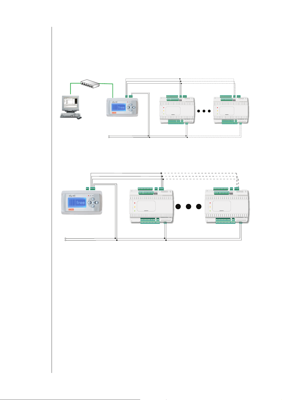
3.4.1 Example: RS485 connection (Field)
1 FREE Panel EVP
Max 127 FREE Evolution EVE expansion modules connected in RS485
o E
VP is in Modbus RTU Master mode
o EVEs are in Modbus RTU Slave mode
485 GS
485 -
485 +
Switch/Router
Ethernet
FREE Studio / Supervisor
POWER IN
EVP
24Va/c
CAN GS
CAN H
CAN L
48Va
POWER IN
<IMG INFO>
3.4.2 CAN connection example (Field)
1 FREE Panel EVP
Max 12 FREE Evolution EVE expansion modules connected in CAN
EVE
1
485 GS
485 -
485 +
max 127
EVE
127
max 12
24Va/c
48Va
EVP
EVE
EVE
FREE Panel
10/38
Page 11
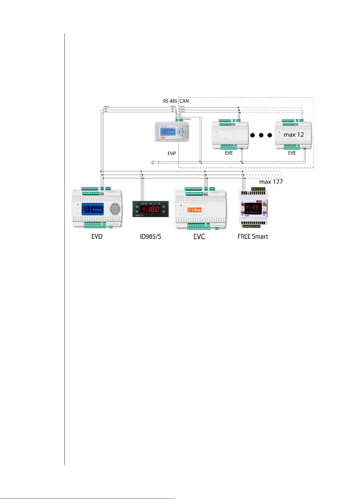
3.4.3 Example: RS485 connection with FREE Smart network
1 FREE Panel EVP
Max 127 FREE Evolution EVD/EVC or FREE Smart or Eliwell and/or third-party instruments equipped with
RS485 serial
CAN n
VP is in Modbus RTU Master mode
o E
o All devices equipped with RS485 are in
modules)
etwork – see CAN connection example
Modbus RTU Slave mode (including the FREE Evolution
FREE Panel
11/38
Page 12
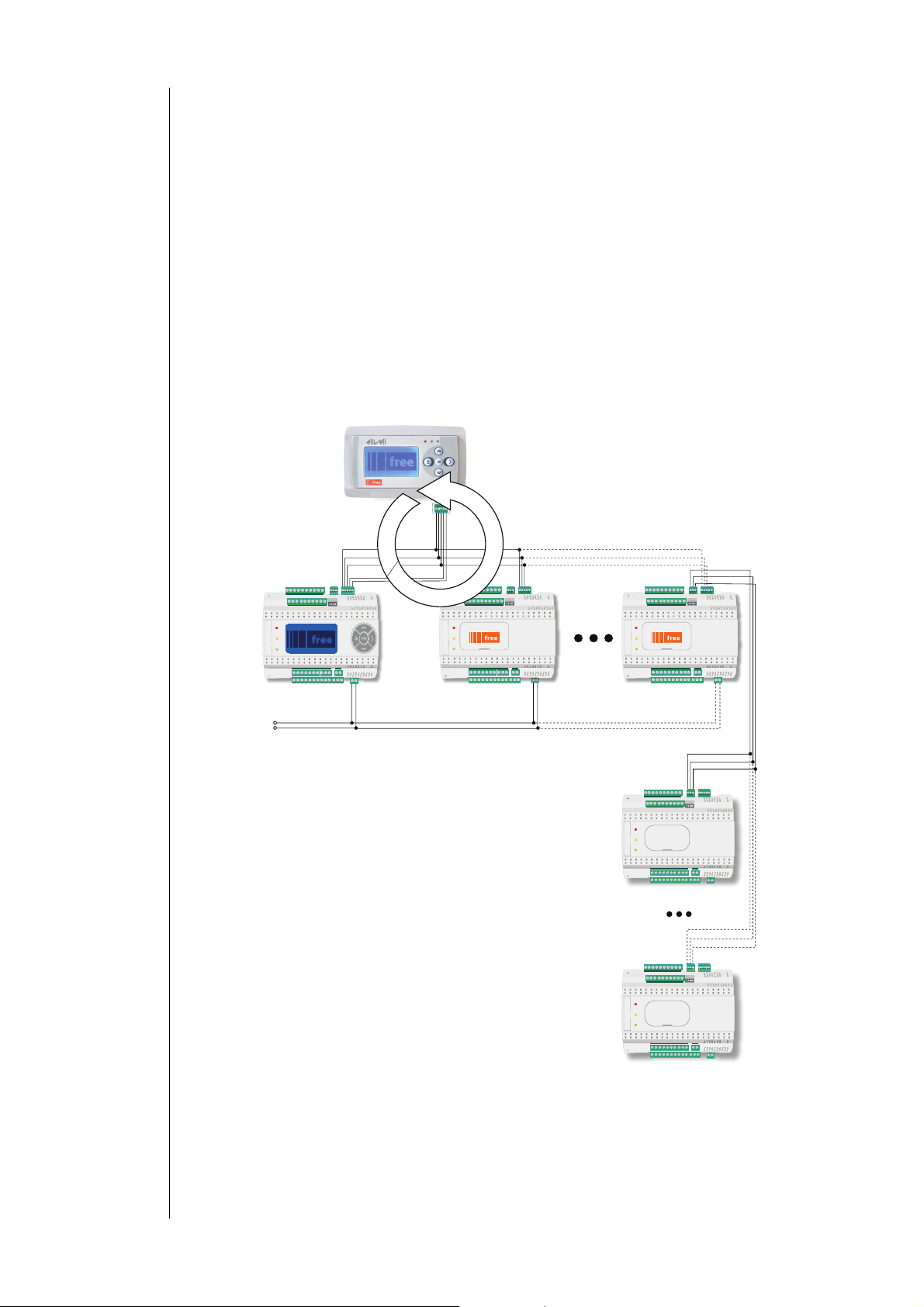
3.4.4 CANopen network connection example
1 FREE Panel EVP
Max 10 FREE Evolution EVD/EVC
CAN n
etwork – see CAN connection example (Field)
HMI menu
EVP can be e
In this case EVP is programmed with the network menu, which can re
quipped with its own menu (named Network menu)
ad variables present in the Evolution controller
network
EVP can o
perate from the terminal of the individual controllers and download up to 10 remote menus from the respective
Evolution controllers
In this case the remote menu allows 'local' navigation of the individual Evolution controller
PLC
The variables of the various controllers are shared (bound together)
A PLC present on EVP can
use variables present in the network and share its own variables with other PLCs present on the
respective Evolution controllers
EVP
24Va/c
48Va
EVD
1
CAN GS
CAN H
CAN L
POWER OUT
POWER
CAN
POWER
Binding
CAN GS
CAN H
CAN L
485 GS
485 -
485 +
max 10
EVC
2
EVC
10
485 GS
485 -
485 +
EVE 1
485 GS
485 -
485 +
EVE 127
FREE Panel
12/38
Page 13

FREE WEB
E
P
BRIDG
The FREE Panel product is also designated FREE WEB
The Ethernet c
Evolution.
FREE WEB
REE Studio allows the creation and management of web pages internally of FREE WEB, i.e. a veritab
F
WEB functionalities allow complete local or remote access by way of an ordinary browser. Thanks to the web connection,
the system provides remote reading and support and remote diagnostics services, as well as e-mail alarm alerts.
Note. Connection to FREE WEB re
NOTE: refer to the section on Parameters / ETHERNET PASSIVE
BRIDGE
REE Studio allows monitoring of FREE Smart tools or third party tools, typically Modbus/RTU slaves, where FREE WEB (or
F
FREE Evolution with Plug-In ETH) is the Master Modbus/RTU.
In a FREE Studio project, more exactly, FREE WEB is u
for Modbus 0x03 and 0x10 commands.
E.g. from FREE Studio, set the connection with FREE Smart as Modbus/TCP, inserting the FREE WEB IP address and the
Modbus/RTU add
onnection also allows communication using HTTP protocol, i.e. access to a Web Server contained in FREE
le website in miniature.
mains possible by way of FREE Studio.
PLUG-IN folder
sed as a Modbus/TCP to Modbus/RTU protocol conversion element
ress of the Smart slave.
Trivial File Transfer Protocol)
TFTP (
TFT
Note. TFTP (Tr
network.
ivial File Transfer Protocol) can also be enabled for file transfer between PC and controller on an Ethernet
FREE Panel
13/38
Page 14

4 TECHNICAL DATA
4.1 General Technical Data
Standard Min. Max.
Supply voltage* 24V~/c ±20%
Power supply frequency 50Hz/60Hz --- ---
Power consumption 5W
Insulation class 2 --- --Ambient operating temperature 25°C -10°C +55°C
Ambient operating temperature of EVK1000 terminal 25°C -5°C +55°C
Ambient operating humidity (non-condensing) 30% 10% 90%
Storage temperature 25°C -20°C +85°C
Ambient storage humidity (non-condensing) 30% 10% 90%
* powered via FREE Evolution EVD/EVC or directly via a transformer
Note: power cable must not be longer than 10m
Classification
The product meets the requirements of the following
Type of disconnection or suspension for each circuit Microswitch disconnection
European Community Directives
and complies with the following harmonized
regulations
Use
Mounting on DIN Omega bar support
Type of action 1.B
Pollution class 2 (normal)
Over voltage category II
Nominal pulse voltage 2500V
Digital outputs refer to the label on the device
Fire resistance category D
Software class and structure A
PTI of materials used for insulation PTI 250V
Period of electrical stress on the insulating parts Long period
EN 60730-2-6 / EN 60730-2-9 / EN 60730-1
in terms of construction, as an independently mounted
temperature-sensitive automatic electronic controller
or
48Vc ±20%
Directive 2006/95/EC
Directive 89/108/EC
21V 60V
4.2 I/O features
Type and
Label
Analogue
inputs
AI1
AI2
configurable
AI3
configurable
AI4
*50mA maximum current @5V; **Clean contact.
Note: Also see Electrical Connections ch
probe Description Resolution Accuracy
On-
board
Remote
NOT
included
Remote
NOT
included
On-
board
NTC 0.1°C/°F
NTC 103AT 0.1°C/°F
NTC NK103 0.1°C/°F
D.I.** 20KΩ
4...20mA 1 digit
0-5V* 1 digit
0..10V 1 digit
On-board
%RH input
apter / Analogue Inputs paragraph for instructions on offsets and calibrations
0.01%RH
(0%=0pt,
100% =
1000pt)
0.5% f.s + 1
digit
0.5% f.s + 1
digit
0.5% f.s + 1
digit
1% f.s +1
digit
1% f.s +1
digit
1% f.s +1
digit
±3%
[20...80%]
±5% …] […
elsewhere
Measurement
range
10KΩ x x
–50…+110 °C
(-58...230°F)
-40…+150 °C
(-40...302°F)
0…1000 100Ω
0…1000 21KΩ
0…1000 21KΩ
0-100 %RH
Impedance
10KΩ
10KΩ
3500
3300
/C
/C
/RH
x x
x
x
Page 15

4.3 Display
backlit with LEDs +
3 LEDs
Note: LED and backlighting can b
Protection rating: The single-mould plastic front cover allows for water resistant panel mounting that is
Display:
Container: backplate + frame in PC+ABS UL94 V-0 plastic resin, front cover in transparent
Monochromatic LCD graphic display 128x64px backlit with LEDs
e controlled from IEC application
comparable to IP65 protection.
polycarbonate, polyester membrane keys
4.4 Serials
Serial Description Notes
CAN Open opto-isolated serial CAN
RS-485 Opto-isolated RS-485 Modbus RTU serial
ETHERNET Modbus TCP/IP ETHERNET port
max50m@500kpbs
200m@125kpbs
Note: 2 jumpers available for
CAN ter
Pay special attention when
connecting serial lines: do not
cable RS485 in
Pack includes MACADDRESS, in
12-digit alphanumeric format
minal resistance
CAN port or
vice versa
barcode and
4.5 Transformer
The instrument must be connected to a suitable current transformer with the following features:
Primary voltage: Depending on requirements of device and/or country of installation
Secondary voltage: 24V~/c - 48Vc ±20%
Power supply fre
Power: 5W min.
quency V~: 50/60Hz
4.6 Mechanical dimensions
Length (L) mm Depth (d)
Space required 160
Hole for panel mounting 68 / 138 (+0.2 mm /
mm
10 96
Height (H) mm Notes
-0.1 mm)
4.7 Permitted use
For safety reasons, the device must be installed and used according to the instructions provided. In particular, parts
carrying dangerous voltages must not be accessible in normal conditions.
The device must be adequately protected from water and dust with regard to the application, and must only be accessible
using tools (with the exception of the front panel).
The device is suitable for use in household and/or similar air conditioning appliances or installations and has been tested
for safety aspects in accordance with harmonized European reference standards.
4.8 Improper Use
Any use other than that expressly permitted is prohibited.
The relay contacts supplied are of the functional type and subject to fault (since they are electronically controlled they are
prone to short-circuiting or remaining open). Any protection devices specified in product standards or suggested by
common sense for obvious safety requirements must be installed externally to the device.
Eliwell is not liable for damage caused by:
Unspecified installation/use and, in particular, in contravention of the safety requirements of established legislation or
specified in this document;
Use on equipment which does not provide adequate protection against electrocution, water and dust in the actual
installation conditions;
Use on equipment in which dangerous components can be
Installation/use on equipment which does not comply with established legislation and standards.
accessed without the use of specific tools;
4.9 Disclaimer
This document is the exclusive property of Eliwell Controls srl and may not be reproduced or circulated unless expressly
authorized by Eliwell Controls srl itself.
Every care has been taken in preparing this document; however, Eliwell Controls srl cannot accept liability for any
damage resulting from its use.
FREE Panel
15/38
Page 16

5 USER INTERFACE
The interface, comprising the front cover of the controller, allows you to perform all operations needed to use the device.
EVP
DIA Menu
5.1 Keys and LEDs
The LEDs can be programmed from the IEC application.
The keys can be
following default settings.
EVP is factory configured with a default DIA
After uploading of an IEC application and/or a HMI menu from FREE Studio, the main display c
menu created with FREE Studio Interface.
In which case, to open the DIAGNOSTICS menu pr
To return to the IEC application menu open the ‘HMI Management’ p
See Remote Interface paragraph
programmed from the IEC application. By default, the device displays a short menu containing the
Key Key
Scroll up
1 UP
2 OK
3 > Moves cursor to right in Edit Mode
4 DOWN
5
Exit
Key combination
4+5
Return to previous page (e.g. 2/10 3/10)
Increase / modify a value
Go to the next label
Scroll down
Move to next level/menu (open folder,
value)
Enter/exit edit mode
Confirm operation
Scroll down
Move to the next page (e.g. 1/102/10)
Decrease / modify a value
Go to previous label
Exit menu page / go back to previous menu
Move cursor to left in Edit Mode
(press and hold) Exit Edit Mode without saving any changes
GNOSTICS (DIA) menu that appears when the instrument is powered on.
oceed as follows:
DOWN
Exit
Press once
(press and release)
subfolder, parameter,
Prolonged press (press and hold for
about 3 seconds)
Open DIAGNOSTICS menu
age, select and press the OK key
onsists of the application
Page 17

5.2 First power on
When the instrument is powered up for the first time, a few summary pages are displayed showing system status (SYSTEM
INFO)
The system will also search for the PLC application and the local menu…
If present, the menu will appear on the display
SYSTEM INFO
HW
BIOS
DATE
BOOT
EEPROM
NOR FLASH OK
NAND FLASH OK
SDRAM OK
BATRAM OK
RTC OK
searching …
PLC
HMI searching …
CON loaded
5.3 DIAGNOSTICS menu
The DIAGONISTICS menu, native to EVP, is used to manage system parameters (BIOS parameters), remote interfaces (HMI)
and to display I/
The DIA menu can be
To change the default language, o
O values and clock
displayed in 5 languages: English, Italian, German, Spanish and French.
pen BIOS Parameters > Display
EVP
BIOS parameters
HMI Management
Probe values
Date and time
5.3.1 BIOS parameters
Parameter configuration menu. See Parameters ch
Note: This menu is depopulated with respect to the parameters tab
FREE Studio device
Language c
BIOS parameters <
select language <
See parameter Display/Hmi_Language
hange example
OK key > Display 1/3 < OK key > Edit Mode < UP/DOWN key >
OK key > < key >
apter.
BIOS parameters
Display
Buzzer
CAN
Display
1/3
Language
Italiano
Display
1/3
Language
English
le contained in the corresponding chapter and in the
FREE Panel
17/38
Page 18

5.3.2 HMI Management
See Remote Interface paragraph
5.3.3 Probe values
Shows input values (read only)
EVP has 3 inputs. Example EVP3500/C/RH
Note: for offset programming see the section on Analogue Inputs in the Connections chapter
5.3.3.1 Date and time
Shows time (HH : MM : SS) and date (DD / MM / YY) of the internal clock
To edit the value press OK. Select the value that you want to modify
Press the OK key to enter Edit Mode. Use the UP and DOWN keys to modify value. Confirm with the OK key
Select ‘Update’ and press OK to update the clock
Probes values
1/3
Internal NTC External NTC Humidity sensor
27.3 - - - - - - - - - - - - - - 43.38
°C, °F °C, °F RH%
Probes values
2/3
Date and time
14 : 45 : 45
20 / 07 / 11
Update
Date and time
16 : 50 : 56
20 / 07 / 11
Update
Probes values
3/3
5.4 Remote interface
Language: 0
5.4.1 Language
This section is for setting the language
The number of languages and the order are established by the corresponding application/menu
See parameter HMI Management/Hmi_Language
5.4.2
o return to the menu of the IEC application, move the cursor onto this symbol and press the OK key
T
See HMI sel
5.4.3 HMI sel
This
section is for setting the menu to be shown on the display
default H
By
Network: this is the EVP ‘local’ menu (local HMI)
rem1…rem10: menus located on max 10 Evolution devices connected to the network that can be
MI menus are NOT present (only the DIA menu is available)
EVP EVP EVP
HMI sel: Network HMI sel: rem1 … HMI sel: rem10
of the remote menu, defined from the FREE Studio User Interface
EVP
HMI sel: Network
COM setting
HMI Management
‘uploaded’ to EVP
FREE Panel
18/38
Page 19

To move from one page to the next press the UP and DOWN keys
After selecting the desired menu move the cursor onto to view the menu
If OK the display
If the menu is not present, the following screen appears
5.4.3.1 COM Setting
This read-only page shows the configuration of the EVP serial ports
5.4.3.2 HMI Management
This page shows the configuration of the 10 remote pages
From these pages it is possible to ‘launch’ (run) the corresponding menu – if present
Move the cursor onto and press the OK key
Note: it will not be possible to launch the local (network) menu from this section
Note: in the example only one remote page is present
To ‘upload’ a remote page use
After selecting the desired menu move the cursor onto to view the menu
Press OK to upload or any other key to cancel
Note: the upload may take up to a minute
If there are no data to upload, the following screen displays
will show the selected menu (IEC application)
EVP
1/10
File: HMIREM.KBD
Id: 0 Id: 0 … Id: 0
Com: CAN Com: CAN Com: CAN
Addr: 125 Addr: 000 Addr: 000
Launch remote page
Please Wait
Warning
Upload failed
Press OK
EVP
CAN : 1 . 500000
485s : 1 . 38400.P81
ETH : 010.000.000.100
EVP
1/10
Upload remote page
Upload page?
The process cannot
be interrupted
Cancel OK
Upload remote page
Uploading…
80%
Attenzione
There are no remote
pages on the card
Press OK
EVP 10/10
FREE Panel
19/38
Page 20

FOLDER
x
LABEL
VAL PAR ADDRESS
RESET (Y/N)
R/W
DATA SIZE
CPL
RANGE
DEFAULT
U.M.
6 PARAMETERS
User-parameterization renders the FREE Panel EVP fully configurable.
Parameters can b
Keys on the EVP front panel
PC and FREE Studio software
The following sections provide a detailed analysis of each parameter, divided into categories (folders).
6.1 Table of parameters
The following table contains all the device configuration parameters available in FREE Studio Device and in the
DIAGNOSTICS (DIA) / BIOS Parameters men
Description of columns:
This indicates the label
A group of these parameters i
Refer also to the following table:
(x) if present (loaded to EVP)
The local menu - if present (uploaded to EVP) - is defined with the Network label
ndicates the label use
This i
Indicates the address of the modbus register containing the resource to be accessed.
Indicates whether the device MUST be rebooted after the parameter has been changed.
Y=YES the device MUST be rebooted to save the change.
N=NO the device DOES NOT need to be rebooted after changing the parameter
Indicates if resources are read/write, read-only or write-only:
Indicates the size of the data in bits.
When the field indicates “-1”, the value read by the register requires conversion, because the value represents a number
with a sign. In other cases the value is always positive or null.
To carry out the conversion, proceed as follows:
If the value in the register is between 0 and 32.767, the result is the value itself (zero and positive values)
If the value in the register is between 32.768 and 65.535, the result is the value of the register – 65.536 (negative
Describes the interval of values that can be
parameters (in
Indicates the factory setting for the standard model of the instrument.
Unit of measure for values converted according to the rules indicated in the CPL co
The unit of measure shown is an example only, as it may change depending on the application (e.g. parameters wit
in °C/bar could also have %RH)
e changed using:
of the FREE Studio Device folder containing the parameter in question
s available on the LCD display in the DIAGNOSTICS (DIA) menu
FOLDER EVP
ACKNOWLEDGEMENT x -
AI CALIBRATION x -
ANALOGUE INPUTS x -
All Parameters
HMI management
d to display the parameters
R The resource is read-only
W The resource is write-only
RW The resource can be bot
values)
dicated in the parameter label).
ON-BOARD RS485 x -
ON-BOARD CAN x x
ETHERNET x x
HMI management x x
HMI remote 1 (rem1) x (x)
HMI remote 10 (rem10)
u
EVP
DIA
(x)
lumn
Display x x
Buzzer:
… x (x)
h read and written to
assigned to the parameter. It can be correlated with other instrument
x x
h a U.M.
6.1.1 Table of parameters
(See next page)
FREE Panel
20/38
Page 21

EVP parameters
FOLDER
ACKNOWLEDGEMENT Par_TAB 15716 WORD Y RW
ACKNOWLEDGEMENT Par_POLI 15717 WORD Y RW
ACKNOWLEDGEMENT Par_PARMOD 15719 BOOL RW
AI CALIBRATION Gain_Ntc_AI1 15616 WORD RW Ai1 NTC calibration gain 0 … 65535 32768 num.
AI CALIBRATION Gain_Ntc_AI2 15617 WORD RW Ai2 NTC calibration gain 0 … 65535 32768 num.
AI CALIBRATION Gain_5V_AI3 15620 WORD RW Ai3 0-5V calibration gain 0 … 65535 32768 num.
AI CALIBRATION Gain_10V_AI3 15621 WORD RW Ai3 0-10V calibration gain 0 … 65535 32768 num.
AI CALIBRATION Gain_mA_AI3 15622 WORD RW Ai3 4-20mA calibration gain 0 … 65535 32768 num.
AI CALIBRATION Offs_Ntc_AI1 15650 WORD -1 RW Ai1 NTC calibration offset -32768 … 32767 0 num.
AI CALIBRATION Offs_Ntc_AI2 15651 WORD -1 RW Ai2 NTC calibration offset -32768 … 32767 0 num.
AI CALIBRATION Offs_5V_AI3 15654 WORD -1 RW Ai3 0-5V calibration offset -32768 … 32767 0 num.
AI CALIBRATION Offs_10V_AI3 15655 WORD -1 RW Ai3 0-10V calibration offset -32768 … 32767 0 num.
AI CALIBRATION Offs_mA_AI3 15656 WORD -1 RW Ai3 4-20mA calibration offset -32768 … 32767 0 num.
LABEL
ADDRESS
PAR. VALUE
DATA SIZE
CPL
R/W
RESET (Y/N)
Map code
Note: read/write parameter
Model Code
Note: read/write parameter
Parameter changed
Flag indicating change to default s
0= map not modified.
1= at least one parameter has been changed from the
original configuration.
DESCRIPTION
ettings.
RANGE
0 … 65535 0 num.
0 … 65535 1025 num.
0 … 1 0 num.
DEFAULT
U.M.
FREE Panel
21/38
Page 22

FOLDER
ANALOGUE
INPUTS
ANALOGUE
INPUTS
ANALOGUE
INPUTS
ANALOGUE
INPUTS
ANALOGUE
INPUTS
ANALOGUE
INPUTS
ANALOGUE
INPUTS
ANALOGUE
INPUTS
ANALOGUE
INPUTS
ANALOGUE
INPUTS Calibration_Ai3
ANALOGUE
INPUTS Calibration_Ai4
ANALOGUE
INPUTS
ANALOGUE
INPUTS
LABEL
Temp_UM 15725 WORD Y RW
Cfg_AI1 15726 WORD RW
Cfg_Ai2 15727 WORD RW
Cfg_Ai3 15728 WORD RW
Cfg_Ai4 15729 WORD RW
FullScaleMin_Ai3 15736 WORD -1 RW
FullScaleMAx_Ai3 15737 WORD -1 RW
Calibration_Ai1 15748 WORD -1 RW
Calibration_Ai2 15749 WORD -1 RW
Compensation_AI1
Compensation_AI4
ADDRESS
PAR. VALUE
15750 WORD -1 RW
15751 WORD -1 RW
15752 WORD -1 RW Internal compensation AI1 -1000 ... 1000 0 °C/10
15753 WORD -1 RW Internal compensation AI4 -1000 ... 1000 0 °C/10
DATA SIZE
CPL
RESET (Y/N)
R/W
DESCRIPTION
Temperature unit of measure
0 = °C;
1 = °F
Type of analogue input Ai1
0= NTC (NK103)
1= DI
2= NTC (103AT)
Type of analogue input Ai2
See Cfg_Ai1
Type of analogue input Ai3
3 = 4…20mA
4=0-10V
5=0-5V
Type of analogue input Ai4
See Cfg_Ai3
Analogue input Ai3 start of scale value
N.B.: Minimum full scale: for current probes, value at 4mA,
for 0-10V voltage probes, value at 0V, 10% for ( 0-5V) probes,
value at 10% (corresponding to 0.5V).
Analogue input Ai3 full scale value
N.B.: Maximum full scale for current probes, value at 20mA,
for 0-10V voltage probes, value at 10V, for (0-5V) probes,
value at 90% (corresponding to 4.5V).
Analogue input Ai1 differential -180 ... 180 0
Analogue input Ai2 differential -180 ... 180 0
Analogue input Ai3 differential -1000 ... 1000 0
Analogue input Ai4 differential -1000 ... 1000 0
RANGE
0 ... 1 0 num.
0 ... 2 2 num.
0 ... 2 2 num.
3 ... 5 3 num.
3 ... 5 3 num.
-9999…+9999 0
-9999…+9999 1000
DEFAULT
U.M.
°C/10
or
°F/10
°C/10
or
°F/10
FREE Panel
22/38
Page 23

FOLDER
RS485
ON BOARD
RS485
ON BOARD
RS485
ON BOARD
RS485
ON BOARD
RS485
ON BOARD
RS485
ON BOARD
ON-BOARD
CAN
ON-BOARD
CAN
LABEL
VAL PAR AdDRESS
Addr_RS485_OB 15774 WORD
Proto_RS485_OB 15775 WORD
Databit_RS485_O
Stopbit_RS485_O
Parity_RS485_OB 15778 WORD
Baud_RS485_OB 15779 WORD
Addr_CAN_
ud_CAN_
Ba
B 15776 WORD Y RW
B 15777 WORD Y RW
OB 15780 WORD Y RW
OB 15781 WORD Y RW
DATA SIZE
CPL
RESET (Y/N)
Y RW
Y RW
Y RW
Y RW
R/W
DESCRIPTION
On-board RS485 serial address
The actual address is determined by the sum of this value +
the value of the dip switch.
On-board RS485 protocol selection
2 = uNET
3 = Modbus/RTU
On-board RS485 data bit number
Fixed setting 8
On-board RS485 stop bit number
1= 1 stop bit
2= 2 stop bit
On-board RS485 protocol parity
0= NULL
1= ODD
2= EVEN
On-board RS485 protocol baudrate
0=9600 baud
1=19200 baud
2=38400 baud
3=57600 baud
4=76800 baud
5=115200 baud
On-board CAN serial address
The actual address is determined by the sum of this value +
the value of the dip switch.
On-board CAN protocol baudrate
2=500 Kbaud
3=250 Kbaud
4=125 Kbaud
5=125 Kbaud
6=50 Kbaud
RANGE
0 ... 255 1 num.
2 ... 3 2 num.
8 ... 8 8 num.
1... 2 1 num.
0 ... 2 2 num.
0 ... 5 2 num.
1 ... 127 1 num.
2 ... 6 2 num.
DEFAULT
U.M.
FREE Panel
23/38
Page 24

ON BOARD ETHERNET
WEB SERVER FUNCTI
The parameters
HTTP and
FREE WEB
HTTP HyperText Transfer Protocol.
An HTTP server generally listens on port 80 using TCP protocol.
TFTP Trivial File
Protocol using basic FTP functionalities. Typical use: transfer of small files between hosts on a network. TFTP USES
The parameters f
DHCP protocol
TFTP ports
allows the use of HTTP and TFTP servers
ONALITY: For more details refer to document 9IS24252_Web_ApplicationNotes
necessary for the configuration of ports and protocols are these:
value
Port_HTTP
Transfer Protocol.
or configuring the PORTS are:
value
Port_TFTP
value
EnableDHCP_ETH
HTTP port
HTTP communication Port number
Default
TFTP port
mmunication Port number
TFTP co
0 corresponds to port 69
Default
Enable DHCP
0 … 1 (False, True)
0 corresponds to port 80
PORT 69
0
False
0
FREE Panel
24/38
Page 25

DNS system
System for the conversion of host names, or network nodes, to IP addresses
Used by FREE Studio to send text e-mails (strings)
value value
PriDNS_1_ETH
PriDNS_2_ETH
PriDNS_3_ETH
PriDNS_4_ETH
Primary DNS server
(part 1)
Primary DNS server
(part 2)
Primary DNS server
(part 3)
Primary DNS server
(part 4)
194 SecDNS_1_ETH Secondary DNS server (part 1) 194
25 SecDNS_2_ETH Secondary DNS server (part 2) 25
2 SecDNS_3_ETH Secondary DNS server (part 3) 2
129 SecDNS_4_ETH Secondary DNS server (part 4) 130
FOLDER
ETHERNET
ON BOARD
ETHERNET
ON BOARD
ETHERNET
ON BOARD
ETHERNET
ON BOARD
ETHERNET
ON BOARD
ETHERNET
ON BOARD
ETHERNET
ON BOARD
LABEL
Port_TFTP 15772 WORD
Port_HTTP 15796 WORD Y RW
Port_ETH 15797 WORD Y RW
Ip_1_ETH 15798 WORD Y RW
Ip_2ETH 15799 WORD Y RW
Ip_3ETH 15800 WORD Y RW
Ip_4ETH 15801 WORD Y RW
ADDRESS
PAR. VALUE
DATA SIZE
CPL
RESET (Y/N)
Y RW
R/W
DESCRIPTION
TFTP port
mmunication Port number Default 0 corresponds to
TFTP co
port 69
HTTP port
HTTP communication Port number Default 0
port 80
Port
TCP/IP Modbus communication port. Port 502 for example
On-board Ethernet passive IP address (part 1) 0 … 255 10 num.
On-board Ethernet passive IP address (part 2) 0 … 255 0 num.
On-board Ethernet passive IP address (part 3) 0 … 255 0 num.
On-board Ethernet passive IP address (part 4) 0 … 255 100 num.
corresponds to
RANGE
0 … 65535 0 num.
0 … 65535 0 num.
0 … 65535 502 num.
DEFAULT
U.M.
FREE Panel
25/38
Page 26

FOLDER
ETHERNET
ON BOARD
ETHERNET
ON BOARD
ETHERNET
ON BOARD
ETHERNET
ON BOARD
ETHERNET
ON BOARD
ETHERNET
ON BOARD
ETHERNET
ON BOARD
ETHERNET
ON BOARD
LABEL
DefGtwy_1_ETH 15802 WORD Y RW
DefGtwy_2_ETH 15803 WORD Y RW
DefGtwy_3_ETH 15804 WORD Y RW
DefGtwy_4_ETH 15805 WORD Y RW
NetMsk_1_ETH 15806 WORD Y RW
NetMsk_2_ETH 15807 WORD Y RW
NetMsk_3_ETH 15808 WORD Y RW
NetMsk_4_ETH 15809 WORD Y RW
ADDRESS
PAR. VALUE
DATA SIZE
CPL
RESET (Y/N)
R/W
DESCRIPTION
Default Gateway (part 1) 0 … 255 192 num.
Default Gateway (part 2) 0 … 255 168 num.
Default Gateway (part 3) 0 … 255 0 num.
Default Gateway (part 4) 0 … 255 1 num.
Net mask (part 1) 0 … 255 255 num.
Net mask (part 2) 0 … 255 255 num.
Net mask (part 3) 0 … 255 255 num.
Net mask (part 4) 0 … 255 0 num.
RANGE
DEFAULT
U.M.
FREE Panel
26/38
Page 27

FOLDER
ETHERNET
ON BOARD
ETHERNET
ON BOARD
ETHERNET
ON BOARD
ETHERNET
ON BOARD
ETHERNET
ON BOARD
ETHERNET
ON BOARD
ETHERNET
ON BOARD
ETHERNET
ON BOARD
ETHERNET
ON BOARD
LABEL
PriDNS_1_ETH 15810 WORD Y RW
PriDNS_2_ETH 15811 WORD Y RW
PriDNS_3_ETH 15812 WORD Y RW
PriDNS_4_ETH 15813 WORD Y RW
SecDNS_1_ETH 15814 WORD Y RW
SecDNS_2_ETH 15815 WORD Y RW
SecDNS_3_ETH 15816 WORD Y RW
SecDNS_4_ETH 15817 WORD Y RW
EnableDHCP_ETH 15819 WORD Y RW
ADDRESS
PAR. VALUE
DATA SIZE
CPL
RESET (Y/N)
R/W
DESCRIPTION
Primary DNS server (part 1) 0 … 255 194 num.
Primary DNS server (part 2) 0 … 255 25 num.
Primary DNS server (part 3) 0 … 255 2 num.
Primary DNS server (part 4) 0 … 255 129 num.
Secondary DNS server (part 1) 0 … 255 194 num.
Secondary DNS server (part 2) 0 … 255 25 num.
Secondary DNS server (part 3) 0 … 255 2 num.
Secondary DNS server (part 4) 0 … 255 130 num.
Enable DHCP
RANGE
0 … 1
(False, True)
DEFAULT
False flag
U.M.
FREE Panel
27/38
Page 28

FOLDER
Display Hmi_Language 15819 WORD RW
Display Par_ContrLCD 15723 WORD Y RW
Display Par_BackLightTime 15724 WORD RW
Buzzer Buzzer_Mode 15990 WORD RW
LABEL
ADDRESS
PAR. VALUE
DATA SIZE
CPL
R/W
RESET (Y/N)
Display language
0 = Italian
1 = English
2 = French
3 = German
4 = Spanish
LCD Contrast
Allows adjustment of the LCD display co
Backlight switch-on time
Allows adjustment of LCD display s
Buzzer mode
0= always off
1= beep per key
DESCRIPTION
ntrast.
witch-on time.
RANGE
0 … 65535 0 num.
0 … 64 30 Num.
0 … 3600 10 sec
0 … 1 0 num.
DEFAULT
U.M.
FREE Panel
28/38
Page 29

FOLDER
HMI Management Hmi_Language 15989 WORD RW 0 … 65535 0 num.
HMI Management HmiList_Current 15820 WORD RW
NOTE: if HmiList_Current=11 the following folders/parameters are NOT USED
HMI remote 1 HmiList_ID_1 15821 WORD RW HMI remote 1 navigation ID list 0 ... 254 0 num.
HMI remote 1 HmiList_Res_1 15833 WORD RW
HMI remote 1 HmiList_Addr_1 15845 WORD RW
HMI remote 1 HmiList_Addr_2 15846 WORD RW HMI remote 1 navigation resource address for TCP (IP part 2) 0 ... 255 0 num.
HMI remote 1 HmiList_Addr_3 15847 WORD RW HMI remote 1 navigation resource address for TCP (IP part 3) 0 ... 255 0 num.
HMI remote 1 HmiList_Addr_4 15848 WORD RW HMI remote 1 navigation resource address for TCP (IP part 4) 0 ... 255 0 num.
HMI remote 1 HmiList_File_1 15893 15 byte RW HMI remote 1 navigation file (DOS 8.3 uppercase format) ******** string
HMI remote 2 HmiList_ID_2 15822 WORD RW HMI remote 2 navigation ID list 0 ... 254 0 num.
HMI remote 2 HmiList_Res_2 15834 WORD RW
HMI remote 2 HmiList_Addr_1 15849 WORD RW
HMI remote 2 HmiList_Addr_2 15850 WORD RW HMI remote 2 navigation resource address for TCP (IP part 2) 0 ... 255 0 num.
HMI remote 2 HmiList_Addr_3 15851 WORD RW HMI remote 2 navigation resource address for TCP (IP part 3) 0 ... 255 0 num.
HMI remote 2 HmiList_Addr_4 15852 WORD RW HMI remote 2 navigation resource address for TCP (IP part 4) 0 ... 255 0 num.
HMI remote 2 HmiList_File_2 15901 15 byte RW HMI remote 2 navigation file (DOS 8.3 uppercase format) ******** string
LABEL
ADDRESS
PAR. VALUE
DATA SIZE
CPL
R/W
RESET (Y/N)
Current HMI
0= HMI remote 1
1= HMI remote 2
2= HMI remote 3
3= HMI remote 4
4= HMI remote 5
5= HMI remote 6
6= HMI remote 7
7= HMI remote 8
8= HMI remote 9
9= HMI remote 10
10 = not used
11= Local HMI
HMI remote 1 navigation resource type
1=RTU (RS485 M
2=TCP (Modbus TCP)
3=CAN (C
HMI remote 1 navigation resource address for CAN, RTU and TCP
(IP part 1)
HMI remote 2 navigation resource type
1=RTU (RS485 M
2=TCP (Modbus TCP)
3=CAN (C
HMI remote 2 navigation resource address for CAN, RTU and TCP
(IP part 1)
odbus RTU)
ANopen)
odbus RTU)
ANopen)
DESCRIPTION
RANGE
0 … 11 11 num.
1 … 3 3 num.
0 ... 255 0 num.
1 … 3 3 num.
0 ... 255 0 num.
DEFAULT
U.M.
FREE Panel
29/38
Page 30

FOLDER
HMI remote 3 HmiList_ID_3 15823 WORD RW HMI remote 3 navigation ID list 0 ... 254 0 num.
HMI remote 3 HmiList_Res_3 15835 WORD RW
HMI remote 3 HmiList_Addr_1 15853 WORD RW
HMI remote 3 HmiList_Addr_2 15854 WORD RW HMI remote 3 navigation resource address for TCP (IP part 2) 0 ... 255 0 num.
HMI remote 3 HmiList_Addr_3 15855 WORD RW HMI remote 3 navigation resource address for TCP (IP part 3) 0 ... 255 0 num.
HMI remote 3 HmiList_Addr_4 15856 WORD RW HMI remote 3 navigation resource address for TCP (IP part 4) 0 ... 255 0 num.
HMI remote 3 HmiList_File_3 15909 15 byte RW HMI remote 3 navigation file (DOS 8.3 uppercase format) ******** string
HMI remote 4 HmiList_ID_4 15822 WORD RW HMI remote 4 navigation ID list 0 ... 254 0 num.
HMI remote 4 HmiList_Res_4 15836 WORD RW
HMI remote 4 HmiList_Addr_1 15857 WORD RW
HMI remote 4 HmiList_Addr_2 15859 WORD RW HMI remote 4 navigation resource address for TCP (IP part 2) 0 ... 255 0 num.
HMI remote 4 HmiList_Addr_3 15859 WORD RW HMI remote 4 navigation resource address for TCP (IP part 3) 0 ... 255 0 num.
HMI remote 4 HmiList_Addr_4 15860 WORD RW HMI remote 4 navigation resource address for TCP (IP part 4) 0 ... 255 0 num.
HMI remote 4 HmiList_File_4 15917 15 byte RW HMI remote 4 navigation file (DOS 8.3 uppercase format) ******** string
HMI remote 5 HmiList_ID_5 15825 WORD RW HMI remote 5 navigation ID list 0 ... 254 0 num.
HMI remote 5 HmiList_Res_5 15837 WORD RW
HMI remote 5 HmiList_Addr_1 15861 WORD RW
HMI remote 5 HmiList_Addr_2 15862 WORD RW HMI remote 5 navigation resource address for TCP (IP part 2) 0 ... 255 0 num.
HMI remote 5 HmiList_Addr_3 15863 WORD RW HMI remote 5 navigation resource address for TCP (IP part 3) 0 ... 255 0 num.
HMI remote 5 HmiList_Addr_4 15864 WORD RW
HMI remote 5 HmiList_File_5 15925 15 byte RW HMI remote 5 navigation file (DOS 8.3 uppercase format) ******** string
LABEL
ADDRESS
PAR. VALUE
DATA SIZE
CPL
R/W
RESET (Y/N)
HMI remote 3 navigation resource type
1=RTU (RS485 M
2=TCP (Modbus TCP)
3=CAN (C
HMI remote 3 navigation resource address for CAN, RTU and TCP
(IP part 1)
HMI remote 4 navigation resource type
1=RTU (RS485 M
2=TCP (Modbus TCP)
3=CAN (C
HMI remote 4 navigation resource address for CAN, RTU and TCP
(IP part 1)
HMI remote 5 navigation resource type
1=RTU (RS485 M
2=TCP (Modbus TCP)
3=CAN (C
HMI remote 5 navigation resource address for CAN, RTH and TCP
(IP part 1)
HMI remote 5 navigation resource address for TCP
(IP part 4)
odbus RTU)
ANopen)
odbus RTU)
ANopen)
odbus RTU)
ANopen)
DESCRIPTION
RANGE
1 … 3 3 num.
0 ... 255 0 num.
1 … 3 3 num.
0 ... 255 0 num.
1 … 3 3 num.
0 ... 255 0 num.
0 ... 255 0 num.
DEFAULT
U.M.
FREE Panel
30/38
Page 31

FOLDER
HMI remote 6 HmiList_ID_6 15826 WORD RW HMI remote 6 navigation ID list 0 ... 254 0 num.
HMI remote 6 HmiList_Res_6 15838 WORD RW
HMI remote 6 HmiList_Addr_1 15865 WORD RW
HMI remote 6 HmiList_Addr_2 15866 WORD RW HMI remote 6 navigation resource address for TCP (IP part 2) 0 ... 255 0 num.
HMI remote 6 HmiList_Addr_3 15867 WORD RW HMI remote 6 navigation resource address for TCP (IP part 3) 0 ... 255 0 num.
HMI remote 6 HmiList_Addr_4 15868 WORD RW HMI remote 6 navigation resource address for TCP (IP part 4) 0 ... 255 0 num.
HMI remote 6 HmiList_File_6 15933 15 byte RW HMI remote 6 navigation file (DOS 8.3 uppercase format) ******** string
HMI remote 7 HmiList_ID_7 15827 WORD RW HMI remote 7 navigation ID list 0 ... 254 0 num.
HMI remote 7 HmiList_Res_7 15839 WORD RW
HMI remote 7 HmiList_Addr_1 15869 WORD RW
HMI remote 7 HmiList_Addr_2 15870 WORD RW HMI remote 7 navigation resource address for TCP (IP part 2) 0 ... 255 0 num.
HMI remote 7 HmiList_Addr_3 15871 WORD RW HMI remote 7 navigation resource address for TCP (IP part 3) 0 ... 255 0 num.
HMI remote 7 HmiList_Addr_4 15872 WORD RW HMI remote 7 navigation resource address for TCP (IP part 4) 0 ... 255 0 num.
HMI remote 7 HmiList_File_7 15941 15 byte RW HMI remote 7 navigation file (DOS 8.3 uppercase format) ******** string
HMI remote 8 HmiList_ID_8 15828 WORD RW HMI remote 8 navigation ID list 0 ... 254 0 num.
HMI remote 8 HmiList_Res_8 15840 WORD RW
HMI remote 8 HmiList_Addr_1 15873 WORD RW
HMI remote 8 HmiList_Addr_2 15874 WORD RW HMI remote 8 navigation resource address for TCP (IP part 2) 0 ... 255 0 num.
HMI remote 8 HmiList_Addr_3 15875 WORD RW HMI remote 8 navigation resource address for TCP (IP part 3) 0 ... 255 0 num.
HMI remote 8 HmiList_Addr_4 15876 WORD RW HMI remote 8 navigation resource address for TCP (IP part 4) 0 ... 255 0 num.
HMI remote 8 HmiList_File_8 15949 15 byte RW HMI remote 8 navigation file (DOS 8.3 uppercase format) ******** string
LABEL
ADDRESS
PAR. VALUE
DATA SIZE
CPL
R/W
RESET (Y/N)
HMI remote 6 navigation resource type
1=RTU (RS485 M
2=TCP (Modbus TCP)
3=CAN (C
HMI remote 6 navigation resource address for CAN, RTH and TCP
(IP part 1)
HMI remote 7 navigation resource type
1=RTU (RS485 M
2=TCP (Modbus TCP)
3=CAN (C
HMI remote 7 navigation resource address for CAN, RTU and TCP
(IP part 1)
HMI remote 8 navigation resource type
1=RTU (RS485 M
2=TCP (Modbus TCP)
3=CAN (C
HMI remote 8 navigation resource address for CAN, RTU and TCP
(IP part 1)
odbus RTU)
ANopen)
odbus RTU)
ANopen)
odbus RTU)
ANopen)
DESCRIPTION
RANGE
1 … 3 3 num.
0 ... 255 0 num.
1 … 3 3 num.
0 ... 255 0 num.
1 … 3 3 num.
0 ... 255 0 num.
DEFAULT
U.M.
FREE Panel
31/38
Page 32

FOLDER
HMI remote 9 HmiList_ID_9 15829 WORD RW HMI remote 9 navigation ID list 0 ... 254 0 num.
HMI remote 9 HmiList_Res_9 15841 WORD RW
HMI remote 9 HmiList_Addr_1 15877 WORD RW
HMI remote 9 HmiList_Addr_2 15878 WORD RW HMI remote 9 navigation resource address for TCP (IP part 2) 0 ... 255 0 num.
HMI remote 9 HmiList_Addr_3 15879 WORD RW HMI remote 9 navigation resource address for TCP (IP part 3) 0 ... 255 0 num.
HMI remote 9 HmiList_Addr_4 15880 WORD RW HMI remote 9 navigation resource address for TCP (IP part 4) 0 ... 255 0 num.
HMI remote 9 HmiList_File_9 15957 15 byte RW HMI remote 9 navigation file (DOS 8.3 uppercase format) ******** string
HMI remote 10 HmiList_ID_10 15830 WORD RW HMI remote 10 navigation ID list 0 ... 254 0 num.
HMI remote 10 HmiList_Res_10 15842 WORD RW
HMI remote 10 HmiList_Addr_1 15881 WORD RW
HMI remote 10 HmiList_Addr_2 15882 WORD RW HMI remote 10 navigation resource address for TCP (IP part 2) 0 ... 255 0 num.
HMI remote 10 HmiList_Addr_3 15883 WORD RW HMI remote 10 navigation resource address for TCP (IP part 3) 0 ... 255 0 num.
HMI remote 10 HmiList_Addr_4 15884 WORD RW HMI remote 10 navigation resource address for TCP (IP part 4) 0 ... 255 0 num.
HMI remote 10 HmiList_File_10 15965 15 byte RW HMI remote 10 navigation file (DOS 8.3 uppercase format) ******** string
LABEL
ADDRESS
PAR. VALUE
DATA SIZE
CPL
R/W
RESET (Y/N)
HMI remote 9 navigation resource type
1=RTU (RS485 M
2=TCP (Modbus TCP)
3=CAN (C
HMI remote 9 navigation resource address for CAN, RTU and TCP
(IP part 1)
HMI remote 10 navigation resource type
1=RTU (RS485 M
2=TCP (Modbus TCP)
3=CAN (C
HMI remote 10 navigation resource address for CAN, RTU and
TCP (IP part 1)
odbus RTU)
ANopen)
odbus RTU)
ANopen)
DESCRIPTION
RANGE
1 … 3 3 num.
0 ... 255 0 num.
1 … 3 3 num.
0 ... 255 0 num.
DEFAULT
U.M.
FREE Panel
32/38
Page 33

Page 34

7 MODELS AND ACCESSORIES
7.1 Models
Model Mounting Dimensions Display
EVP3300/C Panel* 160x96x10mm
EVP3300/C/RH Panel* 160x96x10mm
--------------- (*) low voltage SELV: SAFETY EXTRA LOW VOLTAGE
(**) NOT INCLUDED - low voltage SELV: SAFETY EXTRA LOW VOLTAGE
/C indicates presence of RTC (Real Time Clock)
Accessories
Contact the Eliwell Sales Department for wall-mounting accessories.
Mak
slots, one at the bottom and one at the top, under the corresponding break-open removable doors, preventing the
opening of holes in walls with recessed-wall wiring.
Make all the necessary connections,
following the instructions for panel mounting (see Mounting chapter).
for Wall Mounting
e 4 holes of diameter 4.2mm in the wall at the specified spacing, to fix the backplate. Alternatively use the two side
then insert the EVP terminal (without front) in the backplate, which serves as a panel,
LCD
backlit
LCD
backlit
Accessories
On-board
Analogue
Inputs (*)
1x NTC
1 xNTC
1 x%RH
for Wall Mounting
Remote
Analogue
Inputs
(**)
1xNTC/DI
1x4…20mA/
0-5V/
0..10V
1xNTC/DI
Power supply Serials
CANopen
24V~/c - 48Vc
24V~/c - 48Vc
RS485
ETHERNET
TCP/IP
CANopen
RS485
ETHERNET
TCP/IP
Code EVA00WMRC0000
Backplate for wall mounting
Page 35

Dimensions of wall-mounting backplate
27
145
160
Ethernet
80
mm
90
57
R 1.5
90
83
59
7.2 Accessories
Note: the photos are intended to show the accessories and are by way of example only. The dimensions shown in the
figures are not to scale.
Name Code Description
Converters
and cables
SAR0RA00X701
USB/485 MINI KIT converter
+ USB cable
Documentation /
Notes
USB/CAN converter
Ethernet cable
230V~/24V 25VA transformer
Note: cable must be
than 10m
230V~/24V 35VA transformer
Note: cable must be
than 10m
no longer
no longer
Mounting on DIN rail
Cable
Transformer
EVA00USCA0000
Contact Eliwell
Sales Department
TF111202
TF111205
FREE Panel
35/38
Page 36

Temperature
probes
Name Code Description
SN8D6L4002
Name Code Description
SN691150
SN8DED11502C0
NTC probe NK103C1R1, 4m
Extended range
(polyester, 2-wire cable) IP65;
NTC probe 103AT, 1.5m (plastic
cap, 2-wire cable);
NTC temperature probe 5X20
1.5m TPE IP68
Documentation /
Notes
Instruction Sheet
SN8D6L4002 GB-I
Instruction Sheet
SN8D6L4002 GB-I
Instruction Sheet
SN8T6H1502 GB-I
Documentation /
Notes
Pressure
transducers
1
)
(
Code Description
Software Tools
Demo Case
Contact Eliwell
Sales Department
VAL00033K
Backplate
EVA00WMRC0000 Backplate for wall mounting
(1) Various items available. Contact the Sales Department
2
) Various lengths can be requested
(
GENERAL NOTES:
Eliwell can also
length.
supply a variety of different NTC probes depending on the cable type (PVC or silicon) and
Pressure transducer 4…20mA
male or female connector
Range fr
Depending on model
om -0.5/7bar to 0/50 bar
FREE Studio
Demo case
FREE Evolution
Instruction Sheet
9IS64173
EWPA
EN-IT-ES-DE-FR-RU
Documentation /
Notes
Contact Eliwell Sales
Department
FREE Panel
36/38
Page 37

Page 38

8 ANALITIC INDEX
(
(( 18
A
Accessories.......................................................................
Analogue inputs................................................................
35
9
Analogue Inputs-Probes..................................................6
B
BIOS parameters ............................................................17
BRIDGE ............................................................................ 13
C
CAN......................................................................................6
CAN connection example (Field)................................ 10
CANopen network connection example................... 12
COM Setting.................................................................... 19
Connections.....................................................................
10
Cross references ..............................................................3
D
Date and time................................................................. 18
DIA Menu......................................................................... 16
DIAGNOSTICS menu......................................................
Disclaimer ........................................................................
Display ..............................................................................
17
15
15
E
ELECTRICAL CONNECTIONS...........................................
6
ETHERNET ...........................................................................7
Example: RS485 connection (Field)............................ 10
Example: RS485 connection with FREE Smart
network ........................................................................ 11
F
First power on .................................................................
17
FREE WEB........................................................................ 13
G
General description...........................................................
General Technical Data ............................................
General warnings ..............................................................
3
14
6
H
Highlighting icons:............................................................3
HMI Management ..................................................18; 19
HMI sel.............................................................................. 18
I
I/O features ......................................................................
Improper Use.................................................................
14
15
INTRODUCTION................................................................
K
Keys and LEDs..................................................................
16
L
Language..........................................................................18
M
Mechanical dimensions .............................................
15
MECHANICAL INSTALLATION ...................................
Models..............................................................................
MODELS AND ACCESSORIES .......................................
34
34
Models and Features .......................................................
N
Note: for offset programming see the section on
Analogue Inputs in the Connections chapter......18
P
PARAMETERS...................................................................
Permitted use...................................................................
20
15
Power supply ................................................................... 6
Pressure probes .............................................................. 6
Probe values.....................................................................18
R
References......................................................................... 3
Remote interface ............................................................
18
RS485.................................................................................. 7
S
Serial connections ............................................................ 6
Serials...............................................................................
15
Specifications: ................................................................. 4
T
Table of parameters.......................................................
TECHNICAL DATA...........................................................
20
14
Temperature probes......................................................... 6
TFTP ..................................................................................13
Transformer .....................................................................
15
U
USER INTERFACE.............................................................
16
W
Wiring diagrams ...............................................................
3
5
4
8
Page 39

r
s
T
Eliwell Controls S.
Via dell’ Industria, 15 Zona Industriale Paludi
32010 Pieve d’ Alpago (BL) Italy
Telephone +39 0437 986 111
Facsimile +39 0437 989 066
.l.
Sales:
+39 0437 986 100 (Italy)
+39 0437 986 200 (other countries)
aleseliwell@invensys.com
echnical helpline:
+39 0437 986 250
E-mail eliwell.freeway@invensys.com
www.eliwell.com
FREE Panel
2012/05/
Cod: 9MA10046
© Eliwell Controls s.r.l. 2011-12 All rights
reserved.
 Loading...