

Page 1
EZ-HT / EZ-MT / EZ-LT
EN
Electronic controllers for refrigeration units
Page 2

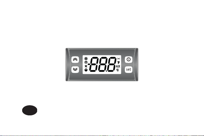
EZ-HT / EZ-MT / EZ-LT USER INTERFACE
UP
Press and release
• Scroll menu items
• Increases values
Press for at least 5 sec
• Activates the Manual Defrost function
DOWN
Press and release
• Scroll menu items
• Decrease values
Press for at least 5 sec
• Function can be configured
by the user (par. H32)
KEYS
STAND-BY (ESC) - ON/OFF
Press and release
• Returns to the previous menu level
• Confirms parameter value
Press for at least 5 sec
• Activates the Standby function (when outside the
menus)
SET (ENTER)
Press and release
• Displays alarms (if active)
• Opens Machine Status menu
Press for at least 5 sec
• Opens Programming menu
• Confirm commands
Page 3
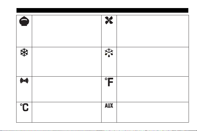
Reduced SET / Economy LED
Flashing: reduced set active
Off: otherwise
LEDS
Fans LED
Permanently on: fans active
Off: otherwise
Compressor LED
Permanently on: compressor active
Flashing: delay, protection or activation
Off: otherwise
Allarm LED
Permanently on: alarm active
Flashing: alarm acknowledged
Off: otherwise
°C LED
Permanently on: °C setting (dro = 0)
Off: otherwise
blocked
Defrost LED
Permanently on: defrost active
Flashing: activated manually or from DI.
Off: otherwise
°F LED
Permanently on: °F setting (dro = 1)
Off: otherwise
NOT USED
Page 4
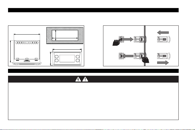
The device is designed for panel mounting. Drill a 71x29 mm (2.80x1.14 in.) hole and insert the instrument; secure it with the special brackets
35 mm - 1.38 in.
59 mm - 2.32 in.
provided. Do not install the device in places subject to high humidity and/or dirt; it is intended for use in sites with ordinary class of pollution.
Keep the area around the instrument cooling slots adequately ventilated.
70 mm - 2.75 in.
29 mm
MOUNTING - DIMENSIONS
1.14 in.
71 mm - 2.80 in.
76.4 mm - 3.01 in.
ELECTRICAL CONNECTIONS
DANGER
HAZARD OF ELECTRIC SHOCK, EXPLOSION OR ARC FLASH
• Disconnect all power from all equipment including connected devices, prior to removing any covers or doors, or installing or
removing any accessories, hardware, cables, or wires.
• Always use a properly rated voltage sensing device to confirm the power is off where and when indicated.
• Replace and secure all covers, accessories, hardware, cables and wires.
• Check the earthing connections on all earthed devices.
• Use only the specified voltage when operating this device and any associated products.
Failure to follow these instructions will result in death or serious injury.
Page 5
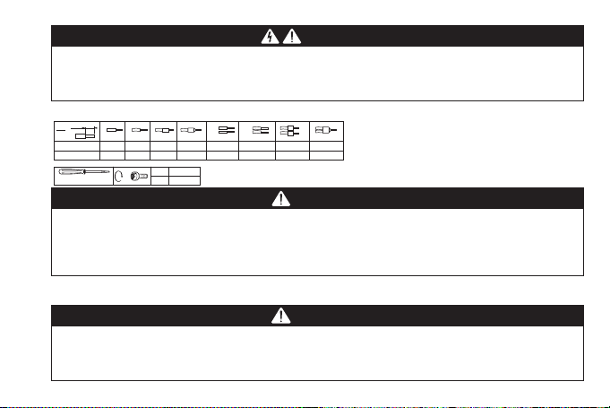
DANGER
LOOSE WIRING CAUSES ELECTRIC SHOCK
Tighten connections in conformance with the torque specifications.
Failure to follow these instructions will result in death or serious injury.
The table below displays the type and the size of cables for disconnectable terminals with pitch 5.00 mm (0.197 in.) or 5.08 mm (0.2 in.).
7
mm
0.28
in.
2
mm
AWG
Ø 3.5 mm (0.14 in.)
0.2…2.5
24…13
0.2…2.5
24…13
C
0.25…2.5
22...13
N•m
lb-in
0.25…2.5
22...13
0.5...0.6
4.42...5.31
2 x 0.2…1
2 x 24…18
2 x 0.2…1.5
2 x 24…16
2 x 0.25…1
2 x 22…18
2 x 0.5...1.5
2 x 20...16
DANGER
POTENTIAL OF OVERHEATING AND FIRE
• Do not use with loads other than those indicated in the technical specification.
• Do not exceed the maximum permitted current; for higher loads, use a contactor with sufficient power capacity.
Failure to follow these instructions will result in death or serious injury.
This device has been designed to operate outside of any dangerous location.
Only install this device in zones known to be free of hazardous atmosphere.
DANGER
POTENTIAL FOR EXPLOSION
Install and use this equipment in non-hazardous locations only.
Failure to follow these instructions will result in death or serious injury.
Page 6
Electrical equipment should be installed, operated, serviced, and maintained only by qualified personnel.
No responsibility is assumed by Eliwell for any consequences arising out of the use of this material.
WARNING
UNINTENDED EQUIPMENT OPERATION
• Use appropriate safety interlocks where personnel and/or equipment hazards exist.
• Install and operate this equipment in an enclosure appropriately rated for its intended environment.
• Power line and output circuits must be wired and fused in compliance with local and national regulatory requirements for the rated
current and voltage of the particular equipment.
• Do not use this equipment in safety-critical machine functions.
• Do not disassemble, repair, or modify this equipment.
• Do not mount devices in extremely damp and/or dirt-laden areas.
Failure to follow these instructions can result in death, serious injury, or equipment damage.
WARNING
UNINTENDED EQUIPMENT OPERATION DUE TO CONNECTION
Signal leads (probes, digital inputs, communication and the signal electronic supply) must be routed separately from power and supply
cables.
Failure to follow these instructions can result in death, serious injury, or equipment damage.
Probes have no connection polarity and can be extended using a regular bipolar cable (note that the extension of the probes affects the EMC
electromagnetic compatibility of the instrument: pay extreme attention to wiring).
Page 7

CONNECTION
N
L
Pb1
41
(thermostat)
N
Pb1
Pb2
(evaporator)
(thermostat)
EZ-MT/EZ-LT
EZ-HT
Power Supply
23 9
Power Supply
45 11
1
23 67 89
L
TTL
10
1
D.I.
TTL
10
D.I.
2-3
Compressor relay
3-4 Power supply input (230 Vac)
N-L Power supply (230 Vac)
9-10 Pb1 probe
10-11 Digital input
TTL TTL input
TERMINALS
1-3
Fans relay
2-3
Compressor relay
5-6-7
Defrost relay
3-4 Power supply input (230 Vac)
N-L Power supply (230 Vac)
8-10 Pb2 probe
9-10 Pb1 probe
10-11 Digital input
TTL TTL input
TERMINALS
Page 8

TECHNICAL DATA (EN 60730-2-9)
Classification: Electronic automatic control (not safety) device for incorporation
Mounting: Panel mounting with 71x29 mm (2.80x1.14 in.) drilling template
Type of action: 1.B
Pollution class: 2
Insulation material group: IIIa
Overvoltage category: II
Nominal pulse voltage: 2500 V
Temperature: Use: –5 … 55 °C (23 ... 131 °F) - Storage: –30 … 85 °C (-22 ... 185 °F)
Power supply: 230 Vac (±10%) 50/60 Hz
Consumption:
Digital output (relay): Refer to the label on the device
Fire resistance category: D
Software class:
NOTE: check the power supply specified on the instrument label; contact our Sales Office for power supply and relay ratings.
4 VA max
A
FURTHER INFORMATION
Input Characteristics
Display range: NTC: –50.0 ... 110 °C (-58.0 ... 230 °F) (on 3-digit display with ± sign)
Accuracy: Better than 0.5 % of full-scale +1 digit
Resolution: 0.1 °C / °F
Buzzer: Depending on model
Analogue Inputs: EZ-HT: 1 NTC/PTC Input - EZ-MT / EZ-LT: 2 NTC/PTC input
Digital input: 1 D.I. voltage free
PTC: –55.0 ... 140 °C (-67.0 ... 284 °F) (on 3-digit display with ± sign)
Page 9

Output Characteristics
Digital output:
MODEL DEFAULT EN60730 (max 250 Vac) UL60730 (max 120 Vac) UL60730 (max 240 Vac)
EZ-HT Compressor 12(8) A 16 FLA - 96 LRA 12 FLA - 72 LRA
Compressor 12(8) A 16 FLA - 96 LRA 12 FLA / 72 LRA
EZ-MT /
Defrost NO 8(4) A - NC 6(3) A
EZ-LT
Fan 5(2) A
Mechanical Characteristics
Housing: PC+ABS UL94 V-0 resin casing, polycarbonate window, thermoplastic resin keys
Dimensions: Front: 76.4x35 mm (3.01x1.38 in.); depth: 59 mm (2.32 in.) (without terminals)
Terminals: Screw terminals for wires with cross-section of 2.5 mm2 (13 AWG)
Connectors: TTL for connection to Copy Card (maximum lenght = 3 m (9.84 ft))
Humidity: Use / Storage: 10 ... 90 % RH (non-condensing)
Regulations
Food Safety: The device complies with standard EN13485 as follows:
(* exclusively using Eliwell probes)
NOTE: The technical specifications stated in this document regarding measurement (range, accuracy, resolution, etc.) refer strictly to the
instrument and not to any accessories provided, such as the probes.
NO 8 A - NC 6 A resistive
1/8 HP
3 A resistive
1.4 FLA / 7.5 LRA
• suitable for storage
• application: air
• climate range A
• measurement class 1 in the range -25 ... 15 °C (-13 ... 59 °F) (*)
NO 8 A - NC 6 A resistive
1/2 HP
3 A resistive
1.4 FLA / 7.5 LRA
Page 10

Alarms are always indicated by the buzzer (if present) and the alarm icon . To switch off the buzzer, press and release any key; the corresponding
icon will continue to flash.
N.B.: If alarm exclusion times have been set the alarm will not be signalled.
• E1: if the Pb1 probe is in error, the indication E1 will appear on the display.
• E2: if the Pb2 probe is in error, the indication E2 will appear on the display. (EZ-MT / EZ-LT only).
ALARMS
DIAGNOSTICS
Label Description Cause Effects Remedy
Pb1 probe
• Measured values are outside
operating range
• Probe inoperable/short-circuited/open
• Measured values are outside
(Defrost)
Pb1 LOW
operating range
• Probe inoperable/short-circuited/open
Value read by Pb1 > HAL after time of
tAO (see 'MAX/MIN TEMP. ALARMS')
alarm
Value read by Pb1 < LAL after time of
tAO (see 'MAX/MIN TEMP. ALARMS')
alarm
AH1
AL1
E1
E2
inoperable
(Cold room)
Pb2 probe
inoperable
Pb1 HIGH
Temperature
Temperature
• Display label E1
• Alarm icon permanently on
• Disable max/min alarm controller
• Compressor operation based on
parameters Ont and OFt
• Display label E2
• Alarm icon permanently on
• The Defrost will end due to Timeout (dEt)
• Recording of label AH1 in folder AL
• No effect on regulation
• Recording of label AL1 in folder AL
• No effect on regulation
• Check probe type (par. H00)
• Check probe wiring
• Replace probe
• Check probe type (par. H00)
• Check probe wiring
• Replace probe
Wait until value read by Pb1
returns below HAL
Wait until value read by Pb1
returns above LAL
Page 11

Label Description Cause Effects Remedy
EA External alarm
Door open
OPd
alarm
Digital input activated
(H11 = ±5)
Digital input activated
(H11 = ±4)
(for longer than tdO)
• Recording of label EA in folder AL
• Alarm icon permanently on
• Regulation locked if rLO = y
• Recording of label OPd in folder AL
• Alarm icon permanently on
• Controller locked
Check and remove the external
cause which triggered the alarm
on the D.I.
• Close the door
• Delay function defined by OAO
MAX/MIN TEMPERATURE ALARMS
Temperature as a
value relative to Setpoint (Att=1)
Temperature as an
Absolute value (Att=0)
Minimum alarm
Maximum alarm
Returning from minimum
temperature alarm
Returning from maximum
temperature alarm
Off
AFd
Setpoint - LAL
Temp. ≤ Set + LAL *
Temp. ≥ Set + HAL **
Temp. ≥ Set + LAL + AFd or
≥ Set - ILALI + AFd (LAL < 0)
Temp. ≤ Set + HAL - AFd (HAL > 0)
Setpoint - LAL + AFd
* if LAL is negative, Set + LAL < Set
** if HAL is negative, Set + HAL < Set
AFd
Setpoint
Setpoint + HAL - AFd
Setpoint + HAL
AFd
LAL
LAL + AFd
Temp. ≤ LAL (LAL with sign)
Temp. ≥ HAL (HAL with sign)
Temp. ≥ LAL + AFd
Temp. ≤ HAL - AFd
HAL - AFd
AFd
HAL
Page 12

PROGRAMMING MENU
To access the Programming menu hold down the key for longer than 5 seconds. If enabled, the instrument will request an access
PASSWORD, either PA1. When accessed the display will show the first parameter (diF). Press and to scroll through all of the
parameters in the current level. Select the desired parameter by pressing .
Press and to change it and to save the changes.
NOTE:Switch the device off and on again each time the parameter configuration is changed.
MACHINE STATUS MENU
Access the Machine Status menu by pressing and releasing the key. If no alarms are active, the SEt label appears.
By pressing the and keys you can scroll through all the folders in the menu:
- SEt: Setpoint setting folder;
- Pb1: probe 1 - Pb1 folder;
- PB2: probe 2 - Pb2 folder *; (EZ-MT / EZ-LT models only)
* folder displayed if Pb2 present (H42 = y)
Setting the Setpoint: To display the Setpoint value press the key when the SEt label is displayed.
Displaying the probes: When labels Pb1, Pb2 are present, press the key to view the value measured by the corresponding probe
- AL: alarms folder (only visible if an alarm is active);
The Setpoint value appears on the display. To change the Setpoint value, press the e keys within 15
seconds. Press to confirm the modification.
(the value cannot be modified).
MANUAL DEFROST CYCLE ACTIVATION
Hold down the key for longer than 5 seconds. It is only activates if the temperature conditions are fulfilled.
Otherwise, the display will flash three times to indicate that the operation will not be performed.
Page 13

The resources are organised into 2 menus which are accessed as follows:
• Machine Status menu: press and release the key.
• Programming menu: hold down the key for 5 seconds.
Either do not press any keys for 15 seconds (timeout) or press the key once, to confirm the last value displayed and return to the previous screen.
INSTRUMENT ON/OFF
ACCESSING AND USING THE MENUS
The instrument can be switched off by pressing the key for longer than 5 seconds. In this condition, the adjustment algorithms and defrost cycles
are disabled and the text 'OFF' will appear on the display.
PASSWORD
Password PA1: used to access User parameters. The password is not enabled by default (PS1=0).
To enable it (PS1≠0): press and hold for longer than 5 seconds, scroll through the parameters using and until you see the label
PS1, press to display the value, modify it using and then save it by pressing or .
If enabled, it will be required in order to access the User parameters.
USING THE COPY CARD
The Copycard must be connected to the TTL serial port and allows the rapid programming of instrument parameters. Access the parameters, using
and until FPr is displayed. Select it using , scroll through the parameters using and and select the function using (e.g. UL).
• Upload (UL): Select UL and press . This function uploads the programming parameters from the instrument to the card. If the procedure
• Format (Fr): This command is used to format the Copycard, (recommended when using the card for the first time).
NOTE: the Fr parameter deletes all data present. This operation cannot be cancelled.
• Download: Connect the Copycard when the instrument is switched off. At power-on, data is downloaded from the Copycard to the instrument
NOTE: After downloading, the instrument works with the settings of the new map just downloaded.
is a success, y, will appear on the display, otherwise n will appear.
automatically. At the end of the lamp test, the display will show dLy if the operation was successful and dLn if not.
Page 14

The keypad can be locked by entering the 'Basic Commands' menu using and pressing and within 2 seconds, or by programming
the LOC parameter. If the keypad is locked, the 'Basic Commands' menu can be accessed and the Setpoint displayed, but the value cannot
be modified.
PARAMETERS TABLE
PAR. DESCRIPTION M.U. RANGE EZ-HT EZ-MT EZ-LT
LOCK SETPOINT MODIFICATION
SEt Temperature control Setpoint. °C/°F
diF Compressor relay activation differential. °C/°F 0.1 ... 30.0 2.0 2.0 2.0
Controller switch-on time in the event of inoperable probe:
Ont
• if Ont = 1 and OFt = 0, the compressor stays on permanently (ON);
• if Ont > 0 and OFt > 0, it operates in Duty Cycle mode.
Controller switch-off time in the event of a inoperable probe:
OFt
• if OFt = 1 and Ont = 0, the compressor stays off permanently (OFF);
• if Ont > 0 and OFt > 0, it operates in Duty Cycle mode.
dOn Compressor relay activation delay after request. s 0 ... 250 0 0 0
dOF Delay after switching off and subsequent switch-on. min 0 ... 250 0 0 0
dbi Delay between two consecutive compressor switch-on. min 0 ... 250 0 0 0
Delay in activating outputs after the instrument is switched on or after a
OdO
power failure. 0 = Not active.
Interval between the start of two consecutive defrost cycles.
dit
0 = Function disabled.
*EZ-HT: 1.0 ...18.0 °C / °F; EZ-MT: -15.0 ... 5.0 °C / °F; EZ-LT: -30.0 ... -10.0 °C / °F
(*)
3.0 0.0 -18.0
min 0 ... 250 15 15 15
min 0 ... 250 15 15 15
min 0 ... 250 0 0 0
hours 0 ... 250 6 6 6
Page 15

PAR. DESCRIPTION M.U. RANGE EZ-HT EZ-MT EZ-LT
Type of defrost.
0 = Electric defrosting - compressor OFF during defrosting;
dtY
1 = Reverse cycle defrost (hot gas) - compressor ON during defrosting;
2 = ‘Free’: defrost independent of compressor.
Selects the count mode for the defrost interval.
0 = Compressor operating hours (DIGIFROST® method); defrosting
active only if compressor is on;
1 = Equipment operating hours; defrost counting is always active when
dCt
the machine is on and start every time the instrument switch on;
2 = Compressor stop; each time the compressor stops a defrosting
cycle is performed according to parameter dtY;
3 = Not used.
dOH Defrost start delay time after request. min 0 ... 59 0 0 0
dEt Defrost time-out; determines the maximum defrost duration. min 1 ... 250 20 25 25
dSt Defrost end temperature. °C/°F -67.0 ... 320 8.0 8.0
Determines if the device should switch to defrost at switch-on
dPO
(depending on the evaporator temperature read).
n(0) = No, no defrost at switch-on; y(1) = Yes, defrost at switch-on.
Characterises parameter FSt which can be expressed either as an
FPt
absolute temperature value or as a value relative to the setpoint.
0 = Absolute; 1 = Relative.
FSt Fans stop temperature; if Pb2 > FSt, the fans are stopped. °C/°F -67.0 ... 320 2.0 2.0
FAd Fans activation intervention differential (see par. FSt). °C/°F 1.0 ... 50.0 2.0 2.0
Fdt Fans activation delay after a defrost cycle. min 0 ... 250 3 3
num 0/1/2 0 0
num 0 ... 3 1 1 1
flag n/y n n n
flag 0/1 0 0
Page 16

PAR. DESCRIPTION M.U. RANGE EZ-HT EZ-MT EZ-LT
dt drainage time. Coil drainage time. min 0 ... 250 5 5
Allows exclusion of the evaporator fans to be selected or not during
dFd
defrosting. n(0) = No (it depends on FCO); y(1) = Yes (fans excluded).
flag n/y y y
Allows to select compressor fans lock OFF (switched off).
H42 FCO COMPRESSOR ON COMPRESSOR OFF
FCO
HAL and LAL parameters mode, i.e. the absolute temperature value or
Att
differential in relation to the setpoint.
0 = Absolute value; 1 = Relative value.
Thermostat controlled OFF
0
Thermostat controlled Thermostat controlled
1
Not used Not used
2
H42 = y
H42 = n
Not used Not used
3
0
1
2
3
ON OFF
Not used Not used
Not used Not used
Not used Not used
num 0 ... 3 1 1
flag 0/1 0 0 0
AFd Alarms activation differential. °C/°F 1.0 ... 50.0 2.0 2.0 2.0
Temperature value (intended either as distance from setpoint or as an
HAL
absolute value based on Att) which, if exceeded in an upward direction,
triggers the activation of the alarm signal.
Temperature value (intended as distance from setpoint or as an absolute
LAL
value based on Att) which, if exceeded in an upward direction, triggers the
activation of the alarm signal.
PAO
Alarm override time after device is switched on following a power outage.
°C/°F
LAL ... 320
50.0 50.0 50.0
°C/°F -67.0 ... HAL -50.0 -50.0 -50.0
hours 0 ... 10 0 0 0
dAO Temperature alarm exclusion time after defrost. min 0 ... 999 0 0 0
Alarm signal delay (low and high temperature) after the deactivation of
OAO
the digital input (port closed).
hours 0 ... 10 0 0 0
Page 17

PAR. DESCRIPTION M.U. RANGE EZ-HT EZ-MT EZ-LT
tdO Delay in door open alarm activation. min 0 ... 250 0 0 0
tAO Time delay for temperature alarm indication. min 0 ... 250 0 0 0
Alarm signalling end of defrost due to timeout.
dAt
n(0) = Alarm not activated; y(1) = Alarm activated.
Regulators locked by external alarm.
rLO
n(0) = Does not lock the regulators; y(1) = Locks the regulators.
Enable utility switch-off on activation of door switch:
dOd
0 = Disabled; 1 = Disables fans;
2 = Disables the compressor; 3 = Disables fans and compressor.
dAd Digital input activation delay. min 0 ... 255 0 0 0
Temperature value to be added to the Setpoint if reduced set enabled
OSP
(Economy function).
Lock. Setpoint change shutdown. It is still possible to enter parameter
LOC
programming mode and modify them. n(0) = No; y(1) = Yes.
PAssword 1.
PS1
When enabled (PS1≠0), this password provides access to parameters.
Display with decimal point
ndt
n(0) = No (integers only); y(1) = Yes (display with decimal point).
Calibration 1. Positive or negative temperature value added to the
CA1
value read by Pb1.
Calibration 2. Positive or negative temperature value added to the
CA2
value read by Pb2.
flag n/y n n
flag n/y n n n
num 0 ... 3 1 1 1
°C/°F -30.0 ... 30.0 0.5 0.5 0.5
flag n/y n n n
num 0 ... 250 0 0 0
flag n/y y y y
°C/°F -12.0 ... 12.0 0.0 0.0 0.0
°C/°F -12.0 ... 12.0 0.0 0.0
Page 18

PAR. DESCRIPTION M.U. RANGE EZ-HT EZ-MT EZ-LT
Display mode during defrost.
0 = Displays the temperature read by probe Pb1;
1 = Locks the reading at the temperature value read by probe Pb1
ddL
when defrosting starts and until the next time the SEt is reached;
2 = Displays the label deF during defrosting and until the next time
the SEt is reached.
Select the unit of measurement used when displaying the
temperature recorded by the probes. 0 = °C, 1 = °F.
dro
NOTE: switching from °C to °F or vice versa DOES NOT modify the
setpoint, differential, etc. (e.g. set=10 °C becomes 10 °F).
Selects type of value to display.
ddd
0 = Setpoint; 1 = Probe Pb1; 2 = Probe Pb2; 3 = Not used.
num 0/1/2 2 0 0
flag 0/1 0 0 0
num 0 ... 3 1 1 1
H00 Probe type selection. 0 = PTC; 1 = NTC; num 0/1 1 1 1
Configuration of digital input 1/polarity (D.I.):
0 = Disabled; ± 1 = Defrost; ± 2 = Reduced set; ± 3 = AUX;
± 4 = Door switch; ± 5 = External alarm; ± 6 = Stand-by (ON-OFF);
H11
± 7, ± 8, ± 9, ±10 = Not used.
NOTE: -
The ‘+’ sign indicates that the input is active when the contact is closed.
- The ‘−’ sign indicates that the input is active when the contact is open.
DOWN key configuration .
H32
0 = Disabled; 1 = Defrost; 2 = AUX;
3 = Reduced set; 4 = Stand-by
;
5,6 = Not used.
num -10 ... 10 0 0 0
num 0 ... 6 0 0 0
H42 Presence of Evaporator probe (Pb2). n(0) = Not present; y(1) = Present. flag n/y y y
UL Upload. Transfer programming parameters from instrument to Copy Card. / / / / /
Fr Formatting. Deletes data on Copy Card. / / / / /
Page 19

ELIWELL CONTROLS SRL declines any liability for damage due to:
- installation/uses different from those specified and, in particular, not complying with the safety regulations and/or instructions given in this
document;
- use on panels that do not provide adequate protection against electric shocks, water or dust when assembled;
- use on panels allowing access to dangerous parts without the use of tools;
- tampering with and/or modifying the product;
- installation/use on panels not complying with current standards and regulations.
This document is the exclusive property of ELIWELL CONTROLS SRL and may not be reproduced or circulated unless expressly authorised by
ELIWELL CONTROLS SRL itself. Every care has been taken in preparing this document; nevertheless ELIWELL CONTROLS SRL cannot accept
liability for any damage resulting from its use. The same applies to any person or company involved in preparing and editing this document.
ELIWELL CONTROLS SRL reserves the right to make aesthetic or functional changes at any time without notice.
Permitted use
For safety reasons, the instrument must be installed and used according to the instructions supplied and, in particular, parts under dangerous
voltages must not be accessible in normal conditions. The device must be adequately protected from water and dust with regard to its application,
and must only be accessible using tools (except for the front panel). The device is suitable for use in household refrigeration appliances and/or
similar equipment and has been tested for safety aspects in accordance with the harmonised European reference standards.
Improper use
Any use other than that expressly permitted is prohibited. The relay contacts provided are of a functional type and subject to failure: any
protection devices required by product standards, or suggested by common sense for obvious safety requirements, must be installed
externally to the instrument.
LIABILITY AND RESIDUAL RISKS
DISCLAIMER
CONDITIONS OF USE
DISPOSAL
The appliance (or the product) must be disposed of separately in compliance with the local standards in force on waste disposal.
Page 20

Eliwell Controls s.r.l.
Via dell’Industria, 15 - Z.I. Paludi
32010 Pieve d’Alpago (BL) ITALY
T: +39 0437 986 111
F: +39 0437 989 066
www.eliwell.com
Technical Customer Support:
T: +39 0437 986 300
E: Techsuppeliwell@schneider-electric.com
Sales:
T: +39 0437 986 100 (Italy)
T: +39 0437 986 200 (other countries)
E: saleseliwell@schneider-electric.com
cod. 9IS54509 • EZ-HT/EZ-MT/EZ-LT • EN • rel. 11/16
© Eliwell Controls s.r.l. 2016 • All rights reserved.
 Loading...