

Eliwell EWRC 300 NT, EWRC 500 NT, WRC 500 NT HACCP, EWRC 500 NT 4DIN, EWRC 500 NT 4DIN HACCP User Manual
...Page 1
EWRC 300/500/5000 NT
Controllers for static and ventilated cold rooms
9MA10258.01
www.eliwell.com
USER
MANUAL
Page 2

This documentation contains the general description and/or technical characteristics of the product
contained herein. This documentation is not intended and must not be used to determine the
appropriateness or reliability of these products related to the user’s specific applications. Every user or
integration specialist must perform their own complete and appropriate risk assessment, evaluations and
tests on the products relating to the specific use or application.
Schneider Electric nor any of its associates or branches shall be held liable or prosecutable for the
improper use of the information contained herein. Users may send us comments and suggestions to
improve or correct this publication.
You hereby accept to not reproduce, other than for personal, non-commercial use, all or part of this
document in any form without the written authorisation of Eliwell. You also accept to not create any
hypertext links to this document or the relative contents. Eliwell shall not grant any rights or licence for
personal and non-commercial use of the document and the relative contents, with the exception of a nonexclusive licence to consult the material “as-is”, at your own risk. All other rights are reserved.
During the installation and use of this product, you must comply with local, national and international
safety laws. For safety reasons and to ensure compliance with the data of the documented system,
component repairs must be performed exclusively by the manufacturer.
When the devices are used for applications with technical safety requirements, comply with the most
relevant instructions. Improper use of Eliwell software (or any other approved software) with Eliwell
hardware products may constitute a risk for personal safety and many cause damage to the equipment.
Failure to comply with these instructions may constitute a risk for personal safety and may cause damage
to the equipment.
© 2018 Eliwell. All rights reserved.
2
9MA10258.01 07/2018
Page 3

CONTENTS
1. INTRODUCTION ............................................................................................................9
1.1. GENERAL DESCRIPTION ...................................................................................................................................9
1.2. MODELS ............................................................................................................................................................... 9
2. TECHNICAL SPECIFICATIONS ............................................................................ 10
2.1. TECHNICAL DATA
(EN 60730-2-9:2010, EN 61439-1:2011 / 61439-2:2011 / EN 60204-1:2006) ........................................10
2.2. ELECTRICAL SPECIFICATIONS .........................................................................................................................10
2.3. FURTHER INFORMATION ..................................................................................................................................11
2.3.1. INPUT CHARACTERISTICS .............................................................................................................................................................11
2.3.2. OUTPUT CHARACTERISTICS .........................................................................................................................................................11
2.3.3. MECHANICAL CHARACTERISTICS ..............................................................................................................................................12
3. MECHANICAL INSTALLATION ............................................................................ 13
3.5. INSTALLATION PROCEDURE ...........................................................................................................................15
4. ELECTRICAL CONNECTIONS .............................................................................. 20
4.1.1. WIRING GUIDELINES ......................................................................................................................................................................20
4.1.2. RULES FOR SCREW-TYPE TERMINAL BOARDS .........................................................................................................................21
4.1.3. ANALOGUE INPUTS-PROBES .......................................................................................................................................................22
4.1.4. SERIAL CONNECTIONS ..................................................................................................................................................................23
4.1.5. RS-485 CONNECTION ...................................................................................................................................................................23
4.1.6. TTL CONNECTION .........................................................................................................................................................................23
4.2. WIRING DIAGRAM ..............................................................................................................................................24
4.2.1. TERMINALS .......................................................................................................................................................................................24
4.3. WIRING DIAGRAM FOR MODELS WITH MAGNETOTHERMAL SWITCH INSTALLED .........................25
4.3.1. TERMINALS .......................................................................................................................................................................................25
5. USER AND START-UP INTERFACE ....................................................................... 26
5.1. DISPLAY .................................................................................................................................................................26
5.1.1. KEYS ....................................................................................................................................................................................................26
5.1.2. ICONS .................................................................................................................................................................................................27
5.1.3. PRELIMINARY CONFIGURATIONS ...............................................................................................................................................28
5.1.4. OPERATION IN DEFAULT CONFIGURATION .............................................................................................................................28
5.1.5. NAVIGATION ....................................................................................................................................................................................29
5.1.6. FUNCTIONS MENU AND KEY-ENABLED FUNCTIONS ...........................................................................................................30
5.1.7. PASSWORDS .....................................................................................................................................................................................31
5.1.8. SETPOINT PROGRAMMING ..........................................................................................................................................................32
5.1.9. VIEWING PROBE VALUES ...............................................................................................................................................................33
5.1.10. HOW TO MODIFY THE DATE AND TIME ..................................................................................................................................34
5.1.11. DISPLAYING ALARMS ..................................................................................................................................................................35
5.1.12. SYSTEM ALARMS EXAMPLE ........................................................................................................................................................36
5.1.13. MODIFYING A PARAMETER .......................................................................................................................................................37
9MA10258.01 07/2018
3
Page 4

6. FUNCTIONS AND REGULATORS ........................................................................ 39
6.1. SETTINGS ............................................................................................................................................................. 39
6.1.1. PROBE SETTING AND CALIBRATION ..........................................................................................................................................39
6.1.2. DISPLAY SETTINGS ..........................................................................................................................................................................39
6.2. FUNCTIONS .........................................................................................................................................................40
6.2.1. UPLOAD, DOWNLOAD, FORMAT ................................................................................................................................................40
6.2.2. UNICARD ...........................................................................................................................................................................................41
6.3. BOOT LOADER FIRMWARE ..............................................................................................................................42
6.4. COMPRESSOR .....................................................................................................................................................43
6.4.1. COMPRESSOR CONFIGURATION ...............................................................................................................................................43
6.4.2. SECOND COMPRESSOR CONFIGURATION .............................................................................................................................43
6.4.3. COMPRESSOR OPERATING CONDITIONS ................................................................................................................................43
6.5. COMPRESSOR/GENERAL PROTECTIONS .................................................................................................... 44
6.5.1. COMPRESSOR SAFETY TIMINGS .................................................................................................................................................45
6.6. DEFROST/DRIPPING ...........................................................................................................................................46
6.6.1. DEFROST TYPE AND ACTIVATION ...............................................................................................................................................46
6.6.2. AUTOMATIC DEFROSTING ...........................................................................................................................................................47
6.6.3. MANUAL DEFROST .........................................................................................................................................................................47
6.6.4. EXTERNAL DEFROST ......................................................................................................................................................................48
6.6.5. DEFROST WITH REMOTE START/STOP .......................................................................................................................................49
6.7. DEFROST MODE .................................................................................................................................................50
6.7.1. DEFROST WITH ELECTRIC HEATERS ...........................................................................................................................................50
6.7.2. INVERSE DEFROST ..........................................................................................................................................................................51
6.7.3. DOUBLE EVAPORATOR DEFROST ...............................................................................................................................................52
6.8. EVAPORATOR FANS ........................................................................................................................................... 54
6.8.1. EVAPORATOR FAN OPERATING CONDITIONS ........................................................................................................................54
6.8.2. FAN OPERATION IN TEMPERATURE CONTROL MODE .........................................................................................................55
6.8.3. FAN OPERATION IN DUTY-CYCLE MODE ..................................................................................................................................56
6.8.4. FAN OPERATION IN DEFROST .....................................................................................................................................................57
6.8.5. FAN FUNCTION DURING DRIPPING ...........................................................................................................................................58
6.8.6. POST-VENTILATION ........................................................................................................................................................................58
6.9. DEEP COOLING CYCLE - DCC .........................................................................................................................59
6.10. PREHEAT .............................................................................................................................................................59
6.11. PRESSURE SWITCH ...........................................................................................................................................60
6.11.1. AUXILIARY OUTPUT (AUX/LIGHT) ..............................................................................................................................................61
6.12. DOOR/EXTERNAL ALARM MANAGEMENT ............................................................................................... 62
6.13. DEMISTING HEATERS (FRAME HEATERS) ................................................................................................... 64
6.14. CONDENSER FANS .......................................................................................................................................... 65
6.15. STAND-BY ...........................................................................................................................................................66
6.16. PUMP DOWN.....................................................................................................................................................66
6.16.1. SERVICE STOPPAGE ......................................................................................................................................................................66
4
9MA10258.01 07/2018
Page 5

7. PARAMETERS ...................................................................................................... 67
7.1. HOW TO MODIFY THE USER PARAMETERS ................................................................................................ 67
7.2. HOW TO EDIT THE INSTALLER PARAMETERS ..............................................................................................67
7.3. PARAMETER TABLE ............................................................................................................................................68
7.3.1. PARAMETER H60..............................................................................................................................................................................78
8. ALARMS ............................................................................................................... 79
8.1. ALARMS AND SIGNALS TABLE ........................................................................................................................ 79
8.2. ALARM CAUSE/EFFECT TABLE ....................................................................................................................... 80
8.3. DESCRIPTION OF ALARMS ............................................................................................................................... 82
8.3.1. PROBE ALARM..................................................................................................................................................................................82
8.3.2. MINIMUM AND MAXIMUM TEMPERATURE ALARM ................................................................................................................83
8.3.3. END OF DEFROST DUE TO TIMEOUT ALARM ..........................................................................................................................84
8.3.4. EXTERNAL ALARM ...........................................................................................................................................................................85
8.3.5. DOOR OPEN ALARM ...................................................................................................................................................................... 85
8.3.6. PRESSURE SWITCH INPUT ALARM ...............................................................................................................................................86
8.3.7. PANIC ALARM ..................................................................................................................................................................................87
8.3.8. LEAK DETECTOR ALARM ...............................................................................................................................................................87
9. MODBUS MSK 554 FUNCTIONS AND RESOURCES ......................................... 89
9.3.1. DATA FORMAT (RTU) .......................................................................................................................................................................89
9.3.2. NETWORK .........................................................................................................................................................................................89
9.3.3. MODBUS COMMANDS AVAILBLE AND DATA AREAS ............................................................................................................90
9.3.4. ADDRESS CONFIGURATION.........................................................................................................................................................90
9.3.5. PARAMETER VISIBILITY AND VALUES ..........................................................................................................................................91
9.3.6. MODBUS TABLES ............................................................................................................................................................................91
9.3.7. PARAMETER/VISIBILITY TABLE ......................................................................................................................................................93
9.3.8. PARAMETER/VISBILITY H60 TABLE ..............................................................................................................................................98
9.3.9. FOLDER VISIBILITY TABLE ..............................................................................................................................................................100
9.3.10. CLIENT TABLE .................................................................................................................................................................................100
10. ADVANCED FUNCTIONS - NIGHT AND DAY ................................................... 102
10.1. DAY/NIGHT REGULATOR OPERATION .......................................................................................................102
10.2. OPERATION WITH DEFROST GROUP..........................................................................................................103
10.3. DAY/NIGHT REGULATOR DURING A BLACKOUT ..................................................................................... 103
10.4. OPENING FOLDER NAD - DAY/NIGHT ........................................................................................................104
11. ADVANCED FUNCTIONS - HACCP .................................................................. 105
11.1. DISPLAYING HACCP ALARMS .......................................................................................................................106
9MA10258.01 07/2018
5
Page 6
SAFETY INFORMATION
Important information
Read these instructions carefully and visually inspect the equipment to familiarise yourself with the device before attempting
to install it, put it into operation, overhaul or service it. The following warning messages may appear anywhere in this
documentation or on the equipment to warn of potential dangers or to call attention to information that can clarify or simplify
a procedure.
The addition of this symbol to a danger warning label indicates the existence of an electrical danger that could
result in personal injury should the user fail to follow the instructions.
This is the safety warning symbol. It is used to warn the user of the potential dangers of personal injury.
Observe all the safety warnings that follow this symbol to avoid the risk of serious injury or death.
DANGER
DANGER indicates a dangerous situation that, unless avoided, will result in death or serious injury.
WARNING
WARNING indicates a potentially dangerous situation which, if not avoided, could result in death or serious injury.
CAUTION
CAUTION indicates a potentially dangerous situation which, if not avoided, could result in minor or moderate injury.
NOTICE
NOTICE used in reference to procedures not associated with physical injuries.
6
9MA10258.01 07/2018
Page 7

NB
The electrical panel (device) must be installed and repaired only by qualified staff. Neither Schneider Electric nor Eliwell
accept any responsibility for any consequences resulting from the use of this material.
A qualified person is someone who has specific skills and knowledge regarding the structure and the operation of electrical
equipment and who has received safety training on how to avoid the inherent dangers.
Product related information
DANGER
HAZARD OF ELECTRIC SHOCK, EXPLOSION OR ARC FLASH
• Disconnect all power from all equipment including connected devices prior to removing any covers or doors, or
installing or removing any accessories, hardware, cables or wires.
• Always use a properly rated voltage sensing device to confirm the power is off where and when indicated.
• Before powering the device back up, fit back and fix all the covers, hardware components and wiring.
• Check the earthing connections on all earthed devices.
• Use only the specified voltage when operating this equipment and any associated products.
• Comply with all standards regarding accident protection and local applicable safety directives.
Failure to follow these instructions will result in death or serious injury.
This equipment is designed to operate outside all hazardous locations and is not to be used in applications which generate
(or could potentially generate) hazardous environments. Install this equipment only in areas and applications known to be
free from dangerous atmospheres at all times.
DANGER
POTENTIAL FOR EXPLOSION
• Install and use this equipment in non-hazardous locations only.
• Do not install or use this equipment in applications which could generate hazardous atmospheres, such as
applications which use flammable refrigerants.
Failure to follow these instructions will result in death or serious injury.
For information regarding the use of control equipment in applications capable of generating hazardous materials, please
contact the relevant national regulatory bodies or certifying authorities.
WARNING
UNINTENDED EQUIPMENT OPERATION
• The equipment signal cables (probes, digital inputs, communication, and the relative power supplies) must be laid
separately from the power cables.
• Every end application of this device must be tested individually and completely in order to check its proper
operation before putting it in service.
Failure to follow these instructions can result in death, serious injury, or equipment damage.
9MA10258.01 07/2018
7
Page 8

Permitted use
The device must be installed and used in accordance with the instructions provided. In particular, parts carrying dangerous
voltages must not be accessible under normal conditions.
It must be adequately protected from water and dust with regard to the application, and must only be accessible using tools
or a keyed locking mechanism (with the exception of the front panel).
The device is suitable for use in household refrigeration appliances and/or similar equipment and has been tested in
accordance with the harmonized European reference standards.
Prohibited use
Any use other than that expressly permitted is prohibited.
The relay contacts provided are mechanical and subject to failure; any protection devices required by product standards, or
suggested by good practice in view of obvious safety requirements, must be installed externally of the device.
Liability and residual risks
The liability of Schneider Electric and Eliwell is limited to the correct and professional use of the product according to the
directives referred to herein and in the other supporting documents, and does not cover any damage (including but not limited
to) the following causes:
• unspecified installation/use and, in particular, in contravention of the safety requirements of the legislation in force in the
country of installation and/or specified in this document;
• use on equipment which does not provide adequate protection against electrocution, water and dust in the actual
installation conditions;
• use on devices which allow access to dangerous parts without the aid of a keyed or tooled locking mechanism;
• tampering with and/or modification of the product;
• installation/use on equipment that does not comply with the regulations in force in the country of installation.
Disposal
The equipment (or product) must be subjected to separate waste collection in compliance with the local legislation on
waste disposal.
Date of production
The date of production is shown on the device label, indicating the week and year of production (WW-YY).
8
9MA10258.01 07/2018
Page 9

1. INTRODUCTION
1.1. GENERAL DESCRIPTION
The Coldface EWRC 300/500/5000 NT series controls the temperature of a static or ventilated cold room. The instrument
controls positive or negative cold rooms and is capable of managing a double evaporator and condenser fan.
Coldface has 3 or 5 configurable relays, depending on the model, and 2(3) configurable digital inputs for door switches or
other devices. Models are available with clock with yearly calendar and HACCP event logging.
The instrument can be connected to TelevisSystem / Modbus via the RS-485 plug-in module (optional).
The container lets you install one or more electromechanical devices, depending on the model.
This summary document contains basic information about the standard
EWRC 300/500/5000 NT models. For further information and custom configurations, refer to the complete user manual
code 9MA0258, available to download from the website www.eliwell.com.
1.2. MODELS
• EWRC 300 NT - Versions with 3 configurable relays for controlling al the accessory loads in the room.
• EWRC 500 NT - Versions with 5 configurable relays for controlling all the accessory loads in the room.
• EWRC 500 NT HACCP - Versions with 5 configurable relays for controlling all the accessory loads in the room, HACCP
function with clock and yearly calendar.
• EWRC 500 NT 4DIN - Versions with 5 configurable relays for controlling all the accessory loads in the room, plus door
for installation of magnetothermal switch or accessories on a DIN rail.
• EWRC 500 NT 4DIN HACCP - Versions with 5 configurable relays for controlling all the accessory loads in the room,
HACCP function with clock and yearly calendar, plus door for installation of magnetothermal switch or accessories on a
DIN rail.
• EWRC 500 NT BREAKER - Versions with 5 configurable relays for controlling all the accessory loads in the room, plus
door and magnetothermal switch installed.
• EWRC 500 NT 4DIN BREAKER HACCP - Versions with 5 configurable relays for controlling all the accessory loads in
the room, HACCP function with clock and yearly calendar, plus door and magnetothermal switch installed.
• EWRC 5000 NT HACCP - Version with larger container, with 5 configurable relays for controlling all the accessory loads
in the room, HACCP function with clock and yearly calendar, plus door for installation of components on a DIN rail
.
9MA10258.01 07/2018
9
Page 10

2. TECHNICAL SPECIFICATIONS
2.1. TECHNICAL DATA
(EN 60730-2-9:2010, EN 61439-1:2011 / 61439-2:2011 / EN 60204-1:2006)
Front panel protection rating IP65
Classification: Electronic automatic control device (not safety device) for stand-alone
installation
Installation: wall
Type of action: 1.B
Pollution class: 2
Panel use: Internal use
Panel type: Fixed panel
Maximum installation site altitude: 2000 m (2187 yd)
Weight: < 2 kg (< 4.41 lb)
Material class: IIIa
Over-voltage category: II
Nominal pulse voltage: 2500 Vac
Operating temperature: -5…50°C (23°F...122°F) (EN 60730-2-9:2010)
Storage temperature: -20…85°C (-20°F...185°F)
Operating humidity: 10…90% non-condensing
Storage humidity: 10…90% non-condensing
Power supply: 230 Vac ±10 % 50/60 Hz
Power consumption: 11 VA max
Magnetothermal switch: EWRC 500 BREAKER: Two-pole (2P)
Control: EWRC NT electronic controller
Connection: device on external flexible cable, Y type connection
Digital outputs (relay): refer to the label on the device
Fire resistance category: D
Software class: A
Ball test temperature: 100°C (212°F)
Clock backup: Up to four days in the absence of an external power supply.
(HACCP models only)
2.2. ELECTRICAL SPECIFICATIONS
Rated voltage (Un): 230 Vac
Rated operating voltage (Ue): 230 Vac
Rated insulation voltage (Ui): 230 Vac
Rated impulse withstand voltage (Uimp): EWRC 500 BREAKER
Rated panel current (InA): EWRC 500 BREAKER
Rated circuit current (InC): EWRC 500 BREAKER
Conditioned short circuit current (Icc): < 4.5 kA
Rated frequency (fn): 50/60 Hz
(1)
EWRC 500 BREAKER RCAS / RCAR
(1)
: 4 kV (EN 61439-2:2011)
(1)
: 16 A (EN 61439-2:2011)
(1)
: 16 A (EN 61439-2:2011)
10
9MA10258.01 07/2018
Page 11

2.3. FURTHER INFORMATION
RCSU
RCH300
OUT1
12(8) A
12FLA - 72LRA
12(8) A
12FLA - 72LRA
12(8) A
12FLA - 72LRA
OUT2
8 A
8FLA - 48LRA
8 A
8FLA - 48LRA
8 A
8FLA - 48LRA
8A resistive
OUT4--
8 A
8FLA - 48LRA
8 A
8FLA - 48LRA
NO 8 A, NC 6 A resistive
NOTE. Maximum common flow rate 16 A for models EWRC 500 BREAKER RCA
/ RCA
Maximum common flow rate 18 A for all other models
2.3.1. INPUT CHARACTERISTICS
Measurement range: NTC: -50.0...110°C (-58°F...230°F); (on 3-digit display with +/- sign)
PTC: -55.0...150°C (-67°F...302°F); (on 3-digit display with +/- sign)
Accuracy: better than 0.5% integral scale + 1 digit
Resolution: 0.1°C (0.1°F)
Buzzer: only on models where this is provided
Analogue inputs: 3(2) configurable NTC/PTC inputs
Digital inputs: 2(3) multi-function, voltage-free digital inputs (DI)
2.3.2. OUTPUT CHARACTERISTICS
RELAY OUTPUTS
MODEL EWRC 300 NT EWRC 500/5000 NT EWRC 500 NT
CODE
STANDARD
OUT3 8(4) A
OUT5 - - NO 8(4) A, NC 6(3) A
RCSH
RCAH
EN60730
max 250 Vac
UL60730
max 240 Vac
4.9FLA - 29.4LRA 8(4) A
EN60730
max 250 Vac
RCAU
UL60730
max 240 Vac
8 A resistive
4.9FLA - 29.4LRA
NO 8 A, NC 6 A resistive
NO 4.9FLA - 29.4LRA
S
RCSP
RCAP
EN60730
max 250 Vac
12(8) A 12FLA - 72LRA
NO 8(4) A, NC 6(3) A
R
NO 4.9FLA - 29.4LRA
UL60730
max 240 Vac
9MA10258.01 07/2018
11
Page 12

2.3.3. MECHANICAL CHARACTERISTICS
Casing: PC+ABS
Dimensions:
front panel 213 x 318 mm, depth 102 mm
front panel 221 x 318 mm, depth 107 mm
front panel 420 x 360 mm, depth 147 mm
Terminals: screw
See “4.1.2. Rules for screw-type terminal boards” page 21
Connectors: TTL for UNICARD / CopyCard / Device Manager connection (via DMI)
Humidity: Operation / Storage: 10...90% RH (non-condensing)
NOTE: The technical specifications stated in this document regarding the measurement (range, accuracy, resolution, etc.)
refer strictly to the instrument and not to any accessories provided, such as the probes.
EWRC 300/500
EWRC 500 BREAKER
EWRC 5000
12
9MA10258.01 07/2018
Page 13

3. MECHANICAL INSTALLATION
3.1. Before starting
Before starting to install your system, read this chapter carefully. Caution must be exercised concerning compliance with all
safety information, other electrical requirements or laws which may apply to your machine or process when using this equipment.
WARNING
REGULATORY INCOMPATIBILITY
Make sure that all equipment used and the systems designed comply with all applicable local, regional and national laws.
Failure to follow these instructions can result in death, serious injury, or equipment damage.
3.2. Disconnection from the power supply
DANGER
HAZARD OF ELECTRIC SHOCK, EXPLOSION OR ARC FLASH
• Disconnect all power from all equipment including connected devices prior to removing any covers or doors, or
installing or removing any accessories, hardware, cables or wires.
• Always use a properly rated voltage sensing device to confirm the power is off where and when indicated.
• Before powering the device back up, fit back and fix all the covers, hardware components and wiring.
• Check the earthing connections on all earthed devices.
• Use only the specified voltage when operating this equipment and any associated products.
• Comply with all standards regarding accident protection and local applicable safety directives.
Failure to follow these instructions will result in death or serious injury.
3.3. Operating environment
Flammable refrigerant gases
This equipment is designed to operate outside all hazardous locations and is not to be used in applications which generate
(or could potentially generate) hazardous environments. Install this equipment only in areas and applications known to be
free from dangerous atmospheres at all times.
DANGER
POTENTIAL FOR EXPLOSION
• Install and use this equipment in non-hazardous locations only.
• Do not install or use this equipment in applications which could generate hazardous atmospheres, such as
applications which use flammable refrigerants.
Failure to follow these instructions will result in death or serious injury.
For information regarding the use of control equipment in applications capable of generating hazardous materials, please
contact the relevant national regulatory bodies or certifying authorities.
9MA10258.01 07/2018
13
Page 14

WARNING
UNINTENDED EQUIPMENT OPERATION
Install and use the equipment in compliance with the conditions described in the Technical Specifications chapter.
Failure to follow these instructions can result in death, serious injury, or equipment damage.
3.4. Comments concerning installation
WARNING
UNINTENDED EQUIPMENT OPERATION
• Use appropriate safety interlocks where personnel and/or equipment hazards exist.
• Do not use this equipment in safety-critical machine functions unless the equipment is otherwise designated as
functional safety equipment and conforming to applicable regulations and standards.
• Do not disassemble, repair, or modify this equipment.
Failure to follow these instructions can result in death, serious injury, or equipment damage.
The devices are designed for wall mounting.
When handling the equipment, use caution to avoid damage caused by electrostatic discharge. In particular, the unshielded
connectors and in certain cases the open circuit boards are vulnerable to electrostatic discharge.
WARNING
UNINTENDED EQUIPMENT OPERATION DUE TO ELECTROSTATIC DISCHARGE
• Keep the equipment in the protective packaging until ready for installation.
• The equipment must only be installed in type-approved casing and/or in points that prevent unauthorised access and
provide protection from electrostatic discharge.
• When handling sensitive equipment, use an antistatic bracelet or equivalent earthed protective device against
electrostatic discharge.
• Before handling the equipment, always discharge the static electricity from the body by touching an earthed surface
or type-approved antistatic mat.
Failure to follow these instructions can result in death, serious injury, or equipment damage.
14
9MA10258.01 07/2018
Page 15
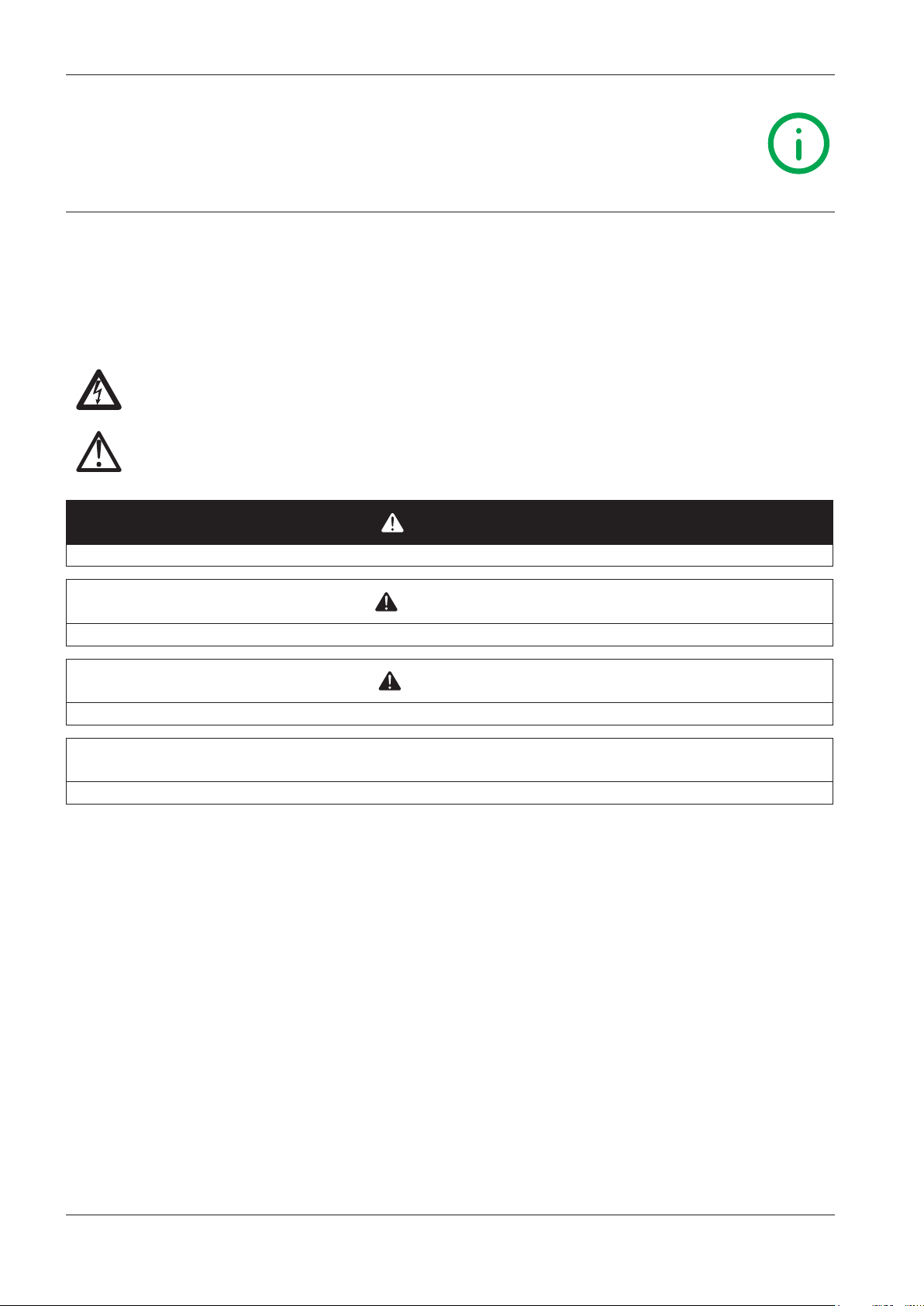
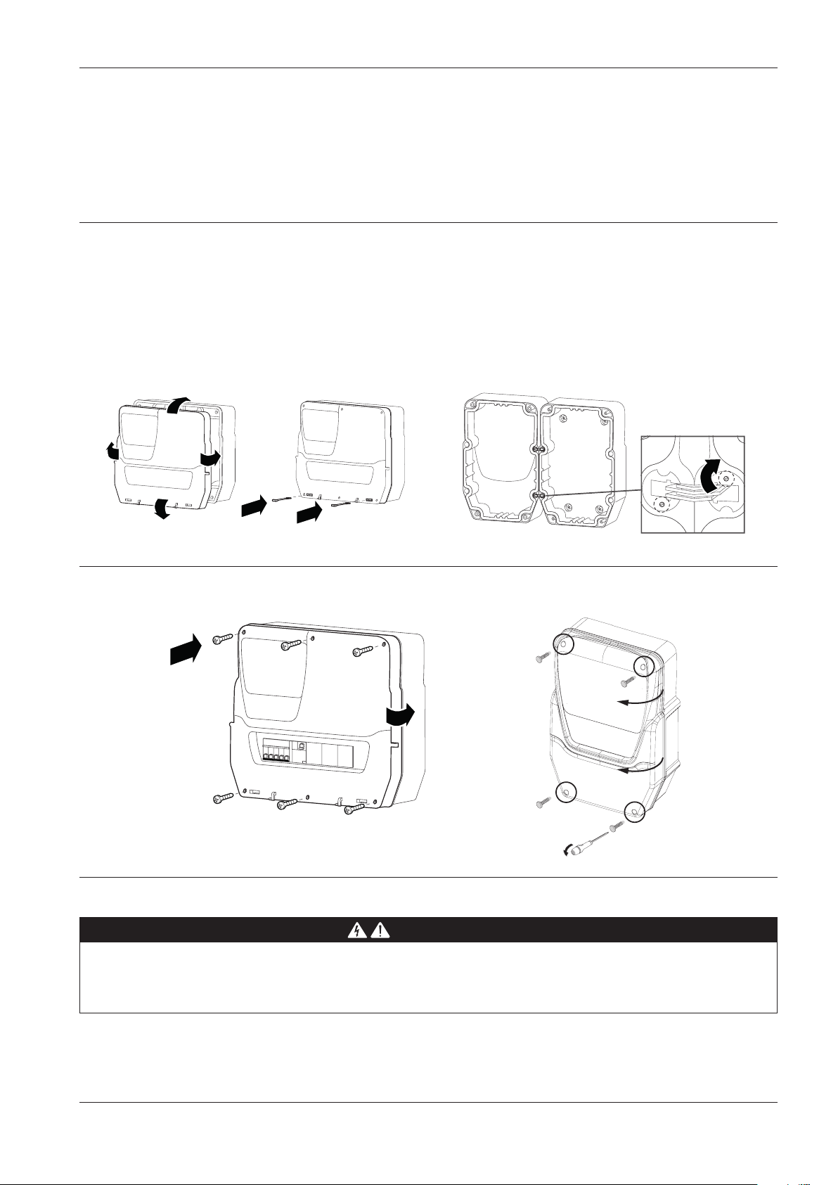
3.5. INSTALLATION PROCEDURE
360 / 14,17 87/ 3,42
NOTE: procedural steps that are common to all models. ONLY the EWRC 5000 model is used as an example.
1) Remove the cover and drill the holes for the cable clamps (at least one for power cables and one for signalling
cables) on the bottom of the panel.
NOTE: for the 300/500 models, use the drilling template provided.
2) Drill the wall fixing holes on the back of the panel, in the areas marked on the back.
mm / in
343 / 13,5
171,5/ 6,75
321,5 / 12,66
UM [mm]
in.
116/ 4,57
A
CD
B
235 / 12,66
EWRC300/500: distance between holes A-B 116 mm (4.57 in.); holes C-D 87 mm (3.42 in.); holes A-C 235 mm (9.25 in.)
Hinges are available for mounting on special compartments for opening the cover both right and left.
Screw on the respective anchoring screws taking care that the hinges are fitted well and lie flush so that they do not
interfere with the compression of the seal.
3) Optional. Fir the panel.
NOTE: on models 300/500 with front door two more DIN spaces
can be created: open the door with both hands as shown in the
figure, then remove the factory-fitted push-through tabs.
9MA10258.01 07/2018
15
Page 16
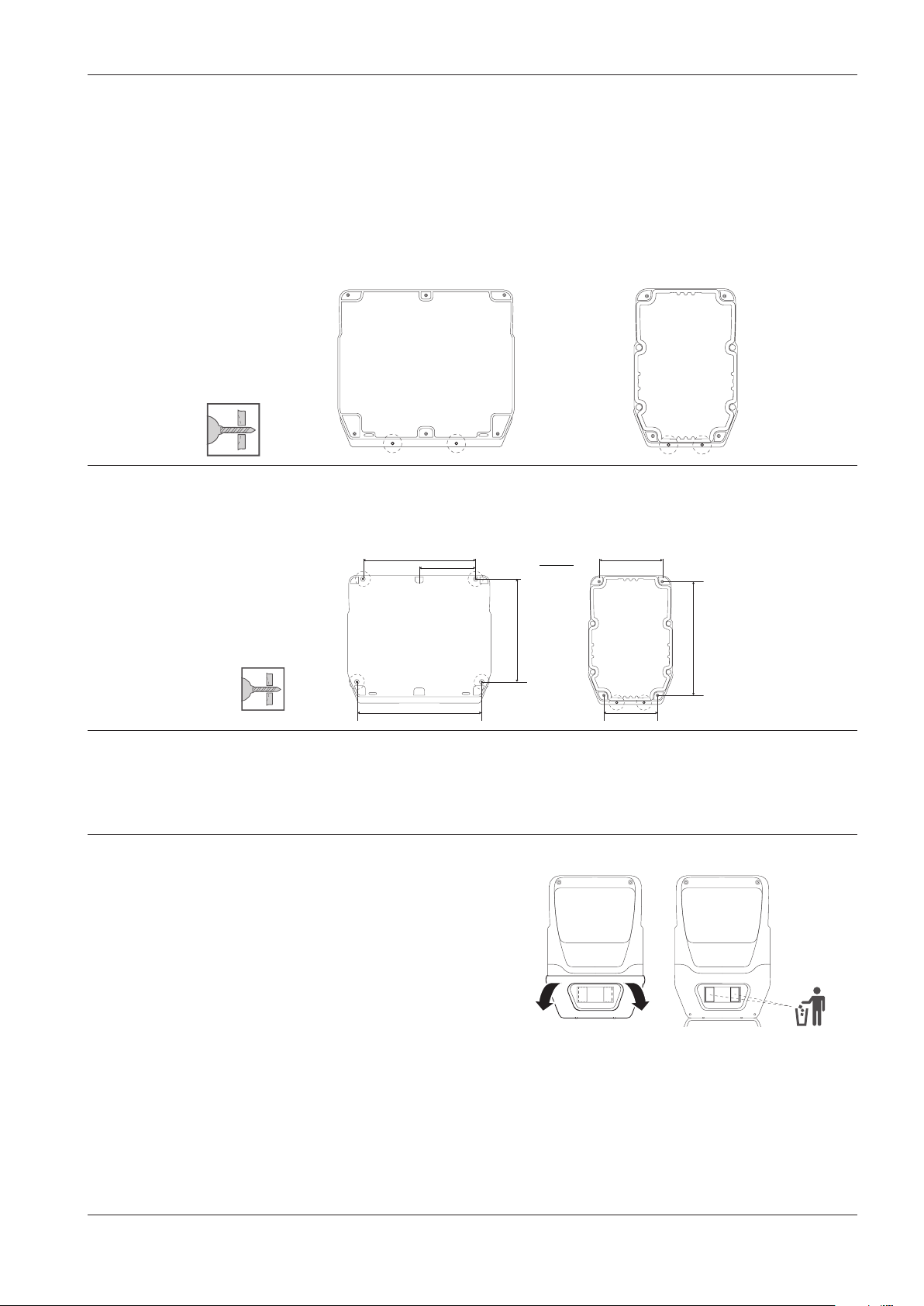
4) Optional. Install the plug-in RS-485 module for
communication with the supervisor.
EWRC 5000 only:
1) Remove the seven screws securing the plastic protecting
the board.
2) Remove the protective element, then use a box cutter to
remove the two terminal covers.
3) Connect the RS-485 plug-in module (optional) using the
specific spacers, then replace the cover and secure it
using the screws.
NOTICE
INOPERABLE DEVICE
Fit the plug-in RS-485 module in the plug-in connector
aligning the four posts with the holes in the control board.
Failure to follow these instructions can result in
equipment damage.
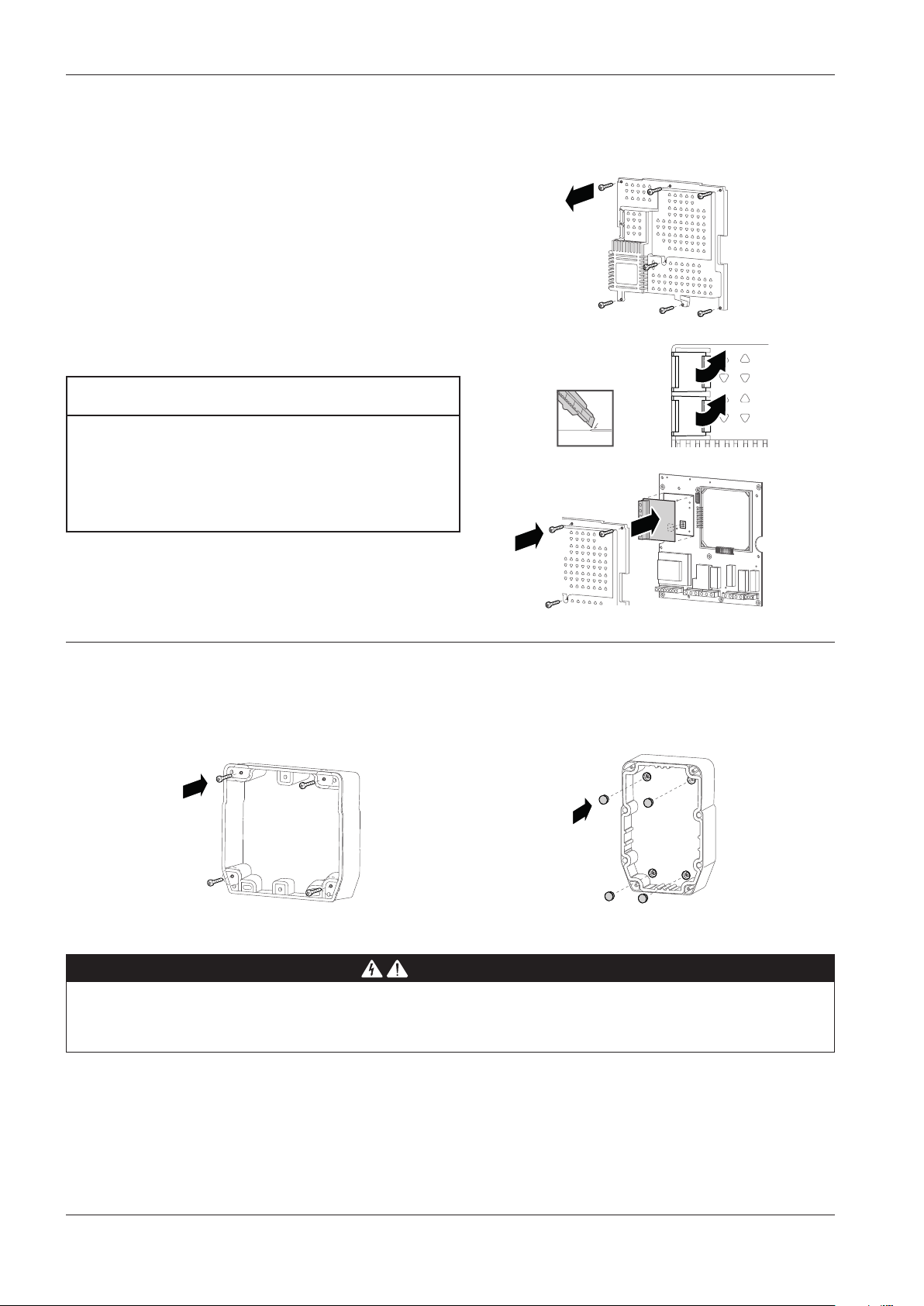
5) Fix the back of the panel to the wall using four screws (not supplied) suited to the wall thickness.
NOTE: TDI20 screw caps (not provided) can be fitted to 300/500 models at the wall mounting points so that the IP
rating is not altered.
DANGER
HAZARD OF ELECTRIC SHOCK, EXPLOSION OR ARC FLASH
For models with magnetothermal switch, before connecting make sure that switch is in the OFF position.
Failure to follow these instructions will result in death or serious injury.
16
9MA10258.01 07/2018
Page 17
6) Make the electrical connections referring to the wiring diagrams shown page 24 and page 25. Use suitable
cable/pipe clamps.
NOTE: only models with magnetothermal switch. Connect the switch to the electronic board power supply using the
accessory cable provided in the packaging.
7) Fit the hinges to secure the cover.
EWRC 5000
Place the panel cover on the base making it stick to the
perimeter seal. Then, while holding the cover in place, fit
the two hinges provided into the corresponding holes and
press them until you hear them click as they are locked
into place.
8) Close the cover and secure it with the screws provided.
EWRC 300/500
Fit the hinges provided into their housings on the right
or left side of the panel and tighten the corresponding
screws to secure them.
DANGER
RISK OF ELECTRIC SHOCK, EXPLOSION OR EXPOSURE TO ACCESSIBLE PARTS
The final application must disallow access to parts at hazardous voltage, as the instrument offers no intrinsic
protection against this risk.
Failure to follow these instructions will result in death or serious injury.
9MA10258.01 07/2018
17
Page 18
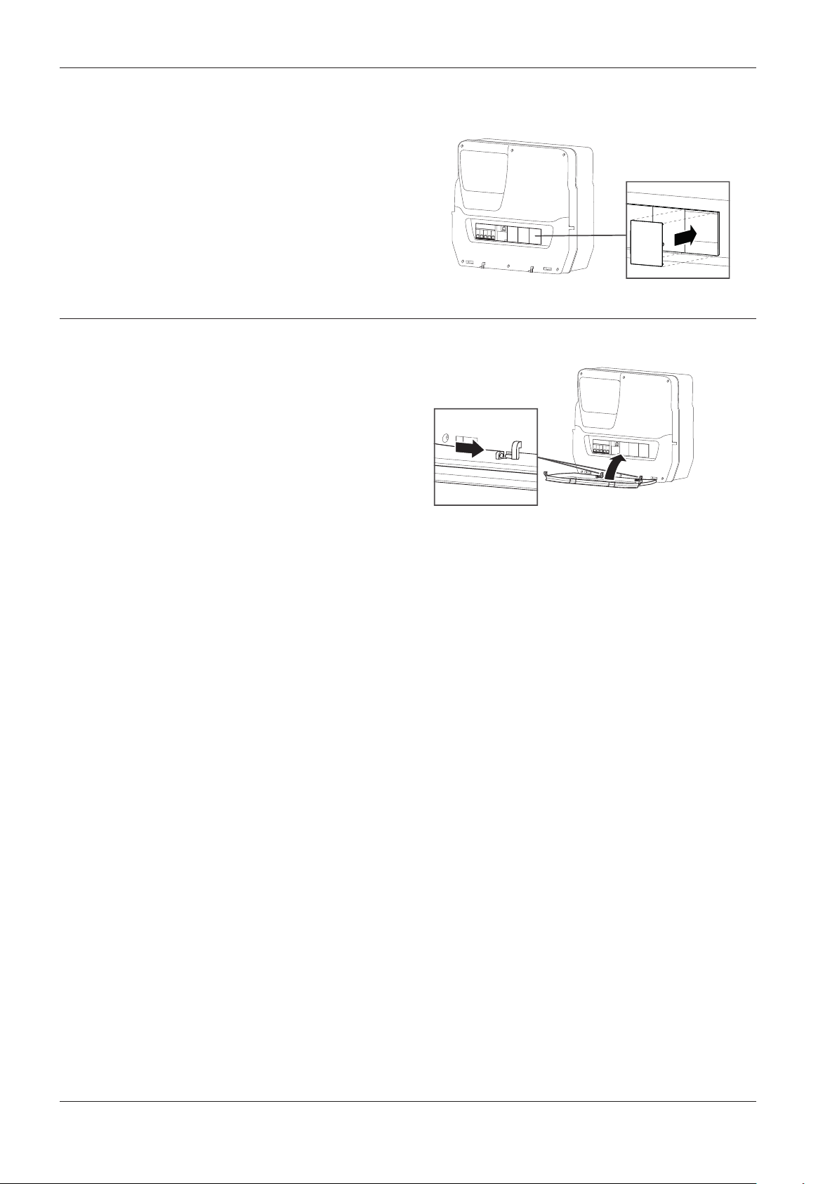
9) DIN rail-mounted models with window only. Close access to
inside the panel from the front window using the dedicated
DIN plugs.
For EWRC NT 500 models with the plastic knockout
removed and no internal magnetothermal switch, the end
user is responsible for ensuring that the open parts of the
box are not accessible.
10) EWRC 5000 only. Fit the door: align the front door with the
two hooks at the bottom of the panel and push it towards the
right until you hear it click as it locks into place.
1
11) Close the door
2
18
9MA10258.01 07/2018
Page 19
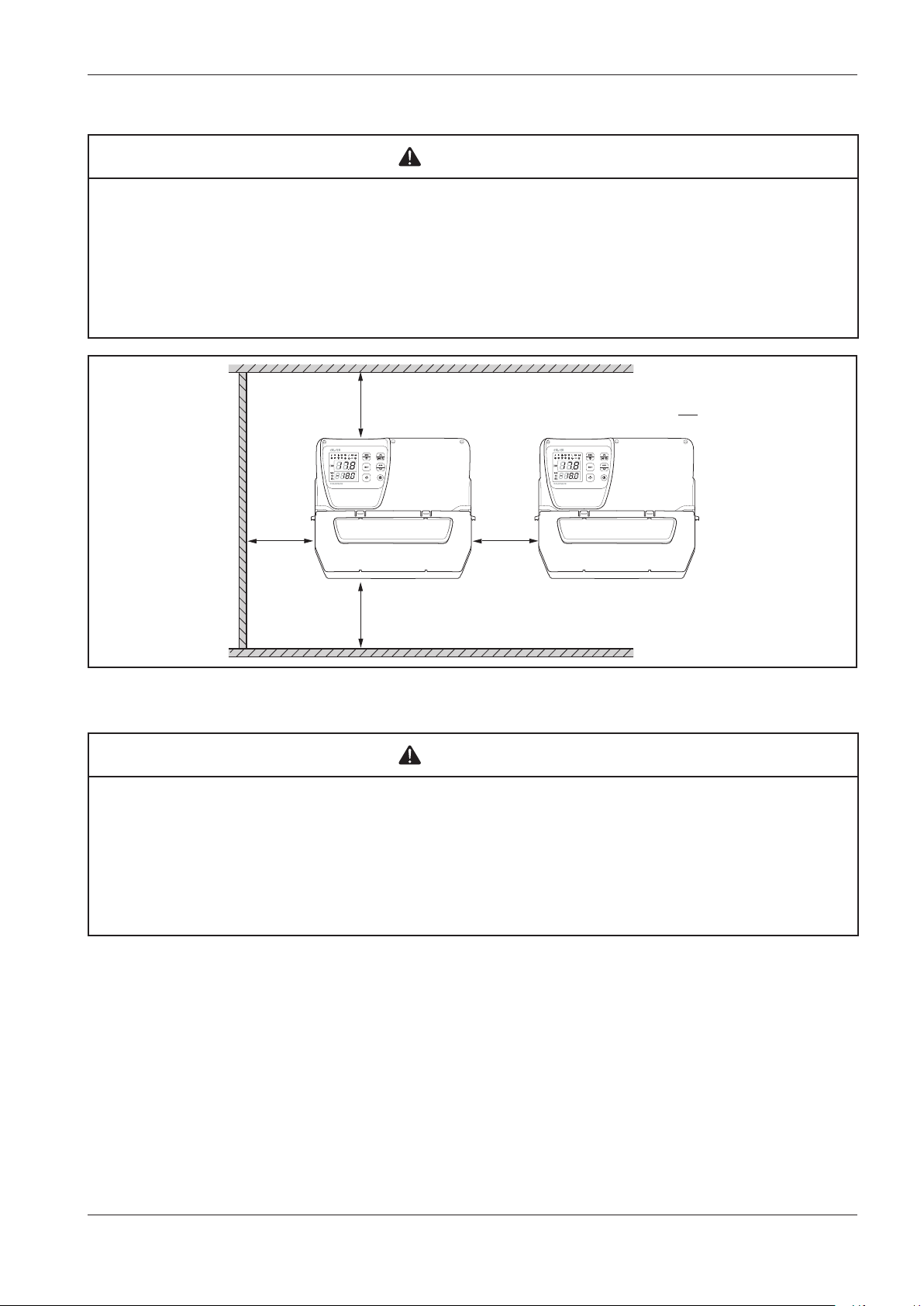
WARNING
UNINTENDED EQUIPMENT OPERATION
• Place the devices dissipating the most heat in the top of the cabinet and ensure suitable ventilation.
• Do not place this equipment near or above any devices which could cause overheating.
• Install the device in a point that guarantees the minimum distances from all structures and adjacent equipment as
indicated in this document.
• Install all equipment in conformity with the technical specifications given in the respective documentation.
Failure to follow these instructions can result in death, serious injury, or equipment damage.
mm
in.
25
9.84
25
9.84
25
9.84
25
9.84
Fig. 1. Distance valid for all models
WARNING
UNINTENDED EQUIPMENT OPERATION
• Place the devices dissipating the most heat in the top of the cabinet and ensure suitable ventilation.
• Do not place this equipment near or above any devices which could cause overheating.
• Install the device in a point that guarantees the minimum distances from all structures and adjacent equipment as
indicated in this document.
• Install all equipment in conformity with the technical specifications given in the respective documentation.
Failure to follow these instructions can result in death, serious injury, or equipment damage.
9MA10258.01 07/2018
19
Page 20

4. ELECTRICAL CONNECTIONS
4.1. Wiring practices
The following information describes the guidelines for wiring and the associated best practices to follow when using the device.
DANGER
HAZARD OF ELECTRIC SHOCK, EXPLOSION OR ARC FLASH
• Disconnect all power from all equipment including connected devices prior to removing any covers or doors, or
installing or removing any accessories, hardware, cables or wires.
• Always use a properly rated voltage sensing device to confirm the power is off where and when indicated.
• Before powering the device back up, fit back and fix all the covers, hardware components and wiring.
• Check the earthing connections on all earthed devices.
• Use only the specified voltage when operating this equipment and any associated products.
• Comply with all standards regarding accident protection and local applicable safety directives.
Failure to follow these instructions will result in death or serious injury.
This equipment is designed to operate outside all hazardous locations and is not to be used in applications which generate (or could
potentially generate) hazardous environments. Install this equipment only in areas and applications known to be free from dangerous
atmospheres at all times.
DANGER
POTENTIAL FOR EXPLOSION
• Install and use this equipment in non-hazardous locations only.
• Do not install or use this equipment in applications which could generate hazardous atmospheres, such as
applications which use flammable refrigerants.
Failure to follow these instructions will result in death or serious injury.
For information regarding the use of control equipment in applications capable of generating hazardous materials, please contact the
relevant national regulatory bodies or certifying authorities.
4.1.1. Wiring guidelines
The following regulations must be complied with for wiring:
• Make connections as short as possible and do not wind them around electrically connected parts.
• Check that the operating conditions and surroundings comply with the specification values.
• Use wires of the correct diameter and suited to the voltage and current requirements.
• Use copper conductors (obligatory).
WARNING
UNINTENDED EQUIPMENT OPERATION
• The equipment signal cables (probes, digital inputs, communication, and the relative power supplies) must be laid
separately from the power cables.
• Every end application of this device must be tested individually and completely in order to check its proper operation
before putting it in service.
Failure to follow these instructions can result in death, serious injury, or equipment damage.
20
9MA10258.01 07/2018
Page 21
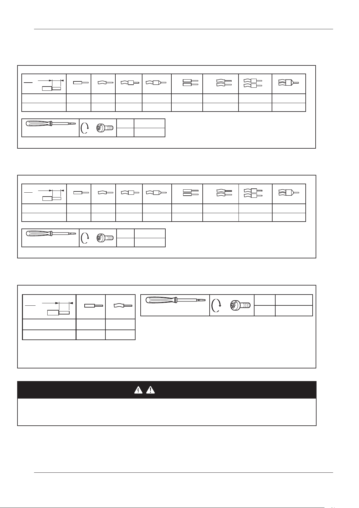
4.1.2. Rules for screw-type terminal boards
The table below illustrates the types of cables and wire sections for a screw-type terminal board with5.08 (0.197 in.) spacing:
7
mm
0.28
in.
2
mm
AWG
Ø 3,5 mm (0.14 in.)
The table below illustrates the types of cables and wire sections for a screw-type terminal board with7.62 (0.30 in.) spacing:
7
mm
0.28
in.
mm
AWG
2
0.2…2.5
24…14
0.2…4
24…12
0.2…2.5
24…14
C
0.2…2.5
24…14
0.25…2.5
22...14
N•m
lb-in
Fig. 2. Spacing 5.08 mm (0.197 in.)
0.25…2.5
22...14
0.25…2.5
22...14
0.5...0.6
4.42...5.31
0.25…2.5
22...14
2 x 0.2…0.75
2 x 24…18
2 x 0.2…1.5
2 x 24…16
2 x 0.2…0.75
2 x 24…16
2 x 0.2…1.5
2 x 24…16
2 x 0.25…0.75
2 x 22…18
2 x 0.25…0.75
2 x 22…18
2 x 0.5...1.5
2 x 20...16
2 x 0.5...1.5
2 x 20...16
0.5...0.6
Ø 3,5 mm (0.14 in.)
The table below illustrates the types of cables and wire sections for the magnetothermal switch:
mm
in.
14
0.55
mm
2
AWG
C
1…25
18…4
Fig. 4. Cable types and tightening torque for the magnetothermal switch
N•m
4.42...5.31
lb-in
Fig. 3. Spacing 7.62 mm (0.3 in.)
Ø 6 mm (0.24 in.)
1…16
18…6
DANGER
C
LOOSE WIRING CAN RESULT IN ELECTRIC SHOCK
Tighten the connections in compliance with the technical specifications for pairs.
Failure to follow these instructions will result in death or serious injury.
N•m
lb-in
2
17.7
9MA10258.01 07/2018
21
Page 22

Specific considerations for handling
When handling the equipment, use caution to avoid damage caused by electrostatic discharge. In particular, the unshielded
connectors and in certain cases the open circuit boards are vulnerable to electrostatic discharge.
WARNING
UNINTENDED EQUIPMENT OPERATION DUE TO ELECTROSTATIC DISCHARGE
• Keep the equipment in the protective packaging until ready for installation.
• The equipment must only be installed in type-approved casing and/or in points that prevent unauthorised access and
provide protection from electrostatic discharge.
• When handling sensitive equipment, use an antistatic bracelet or equivalent earthed protective device against
electrostatic discharge.
• Before handling the equipment, always discharge the static electricity from the body by touching an earthed surface
or type-approved antistatic mat.
Failure to follow these instructions can result in death, serious injury, or equipment damage.
4.1.3. Analogue Inputs-Probes
The temperature probes do not feature any connection polarity and can be extended using normal bipolar cable.
WARNING
UNINTENDED EQUIPMENT OPERATION DUE TO CONNECTIONS
• The equipment signal cables (probes, digital inputs, communication, and the relative power supplies) must be laid
separately from the power cables.
Failure to follow these instructions can result in death, serious injury, or equipment damage.
NOTICE
INOPERABLE DEVICE
Before switching on the electrical power, check all the wiring connections.
Failure to follow these instructions can result in equipment damage.
NOTE: The NTC temperature probes do not feature any connection polarity and can be extended using normal bipolar cable.
22
9MA10258.01 07/2018
Page 23

4.1.4. Serial connections
The controller can be connected to TelevisSystem / Modbus remote control systems by a direct RS-485 connection using
the RS-485 optional plug-in module.
4.1.5. RS-485 connection
• Use a “twisted pair” shielded cable with two conductors with cross-section 0.5 mm2 (AWG 20), plus sheath, such as, for
example, a Belden cable version 3105A (typical impedance 120 Ω) with PVC sheath, rated capacity between conductors
36 pF/m, rated capacity between conductor and sheath 68 pF/m. Alternatively, use a “twisted pair” shielded cable with
two conductors with cross-section 0.5 mm
PVC sheath, rated capacity between conductors 89 pF/m, rated capacity between conductor and sheath 161 pF/m. For
laying wires, comply with the indications given in standard EN 50174 on information technology wiring.
• Follow the applicable regulations for laying and connecting the cables. Extra care must be taken in separating data
transmission circuits from power lines.
• The length of the RS-485 network which can be connected directly to the controller is 1200 m. This length can be
extended and the number of devices for each channel increased using appropriate repeater modules.
• Input impedance: 1/8 unit load.
• Single terminal board with 3 conductors: use all 3 conductors (“+” and “-” for the signal and “GND” for the braiding).
• Attach the 120 Ω 1/4W resistors between the “+” and “-” terminals on the interface and the last controller in each branch
of the network.
• The RS-485 physical level can be used for Modbus SL communication
Concurrent communication of different protocols on the same serial port is NOT permitted.
2
(AWG 20), plus sheath, such as, for example, a Belden cable version 8762 with
Pay special attention when connecting serial lines. Incorrect wiring may cause the equipment to stop working.
NOTICE
INOPERABLE DEVICE
Do not communicate simultaneously via Modbus and Televis protocols on the same serial port.
Failure to follow these instructions can result in equipment damage.
4.1.6. TTL connection
Use a 5-wire TTL cable up to 3 m (118 in.) in length.
An Eliwell-supplied TTL cable is recommended. Contact Eliwell Sales Office for item availability.
9MA10258.01 07/2018
23
Page 24
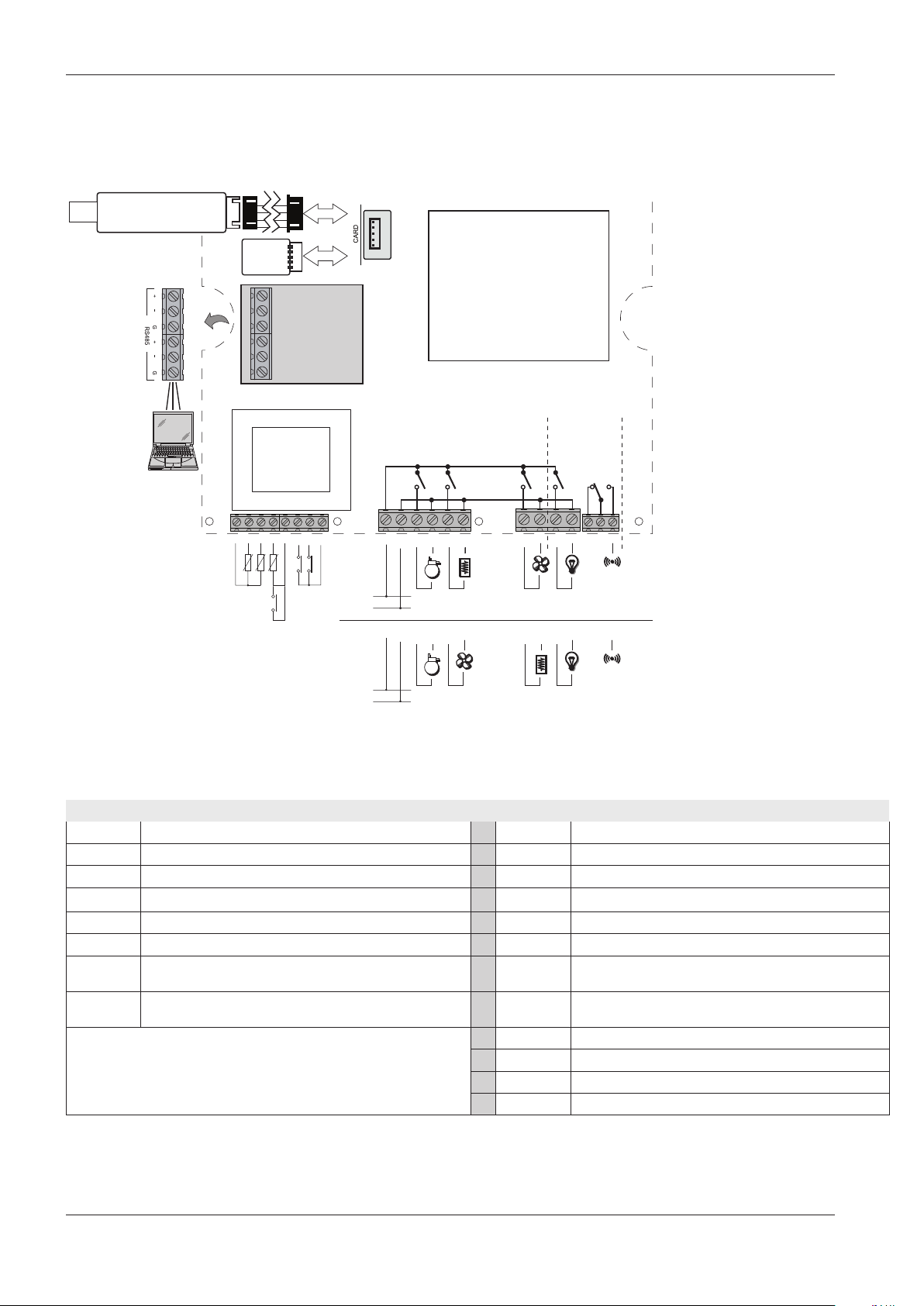
4.2. WIRING DIAGRAM
UNICARD
COPY CARD
GND GND GND+ +
Pb1 Pb2
Yellow cable
+
+
Pb3/DI3
RS-485
OPTIONAL
DI2 DI1
230 Vac
230 Vac
EWRC 300/500/5000 NT
DISPLAY
EWRC 500NT/
5000 NT
1615141312111091 2 3 4 5 6 7 8
H23
only
COM
18 19 20 2117
18 19 20 2117161514131211109
H24 H25
NONC
RCSU
RCSH
RCH300
RCSP
RCAP
OUT1 OUT2 OUT3 OUT4 OUT5
18 A max
L
N
L
N
H22 H23 H24 H25
H21
H22
H21
4.2.1. TERMINALS
TERMINALS
1, 5, 8 GND 9, 10 LINE/NEUTRAL. Power supply
2 Analogue input Pb1 11 NO OUT1
3 Analogue input Pb2 12 NEUTRAL
4 Analogue input Pb3 / Digital input DI3 13 NO OUT2
6 Digital input DI2 14 NEUTRAL
7 Digital input DI1 15 NO OUT3
CARD
RS-485
TTL for connection to UNICARD / CopyCard /
TelevisSystem
Modulo plug-in for connection to
TelevisSystem / Modbus (optional)
16 NEUTRAL
17 NO OUT4
18 NEUTRAL
19 NC OUT5
20 OUT5 Common terminal
21 NO OUT5
24
9MA10258.01 07/2018
Page 25
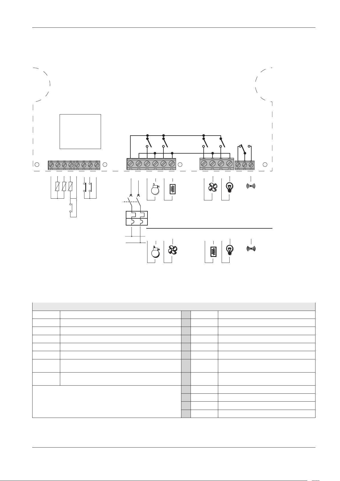
4.3. WIRING DIAGRAM FOR MODELS WITH MAGNETOTHERMAL
H21
H24 H25
H23
H22
SWITCH INSTALLED
EWRC 500 NT BREAKER
OUT1 OUT2 OUT3 OUT4 OUT5
COM
NONC
18 19 20 2117
GND GND GND+ + +
Pb1 Pb2
+
DI2 DI1
H21
H22 H23 H24 H25
1615141312111091 2 3 4 5 6 7 8
RCAU
Pb3/DI3
16 A max
230 Vac
L
N
18 19 20 2117161514131211
RCAP
4.3.1. TERMINALS
TERMINALS
1, 5, 8 GND 9, 10 LINE/NEUTRAL. Power supply
2 Analogue input Pb1 11 NO OUT1
3 Analogue input Pb2 12 NEUTRAL
4 Analogue input Pb3 / Digital input DI3 13 NO OUT2
6 Digital input DI2 14 NEUTRAL
7 Digital input DI1 15 NO OUT3
CARD
RS-485
TTL for connection to UNICARD / CopyCard /
TelevisSystem
Modulo plug-in for connection to
TelevisSystem / Modbus (optional)
16 NEUTRAL
17 NO OUT4
18 NEUTRAL
19 NC OUT5
20 OUT5 Common terminal
21 NO OUT5
9MA10258.01 07/2018
25
Page 26
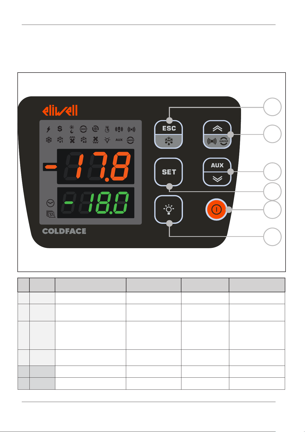
5. USER AND START-UP INTERFACE
5.1. DISPLAY
5.1.1. KEYS
A
B
%RH
No. KEY press and release
A
B
C SET
D
E ON/OFF /
F LIGHT Switch light On/Off Switch light On/Off /
ESC
Defrost
p UP
Alarms
q DOWN
AUX
• Functions Menu
• Alarms Menu (always visible)
• Display setpoint / probe values /
time (Models with clock only)
• Confirm values
• Access value edit mode
(upper display blinking)
system INFO
See Technical Support
press and hold for about
3 seconds
• Manual defrost
• Return to Main Menu
/
Access Parameters menu
Activate auxiliary function
Switch On/Off
device
NAVIGATION MENU Notes
• Increase values
• Confirm values
• Move right
• Decrease values
• Output
• Scroll
• Scroll
/
C
D
E
F
Configurable - see parameter H33
HACCP alarms
only on foreseen models
and if present
Time only visible on models with clock
Configurable - see parameter H32
Configurable - see parameter H34
Configurable - see parameter H35
26
9MA10258.01 07/2018
Page 27
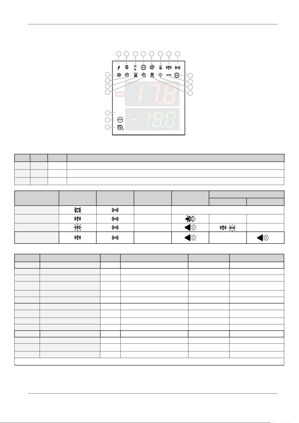
5.1.2. ICONS
1
2 3 4 5 6 7 8
9
10
11
12
17
%RH
18
19
13
14
15
16
Icons have the following meaning:
No. ICON colour description
17 %RH amber not used
18 TIME amber access in case of time display or editing
19 DATA amber access in case of date display or editing
Alarms ICON 7 ICON 8
ALARM Red See “8.2. ALARM CAUSE/EFFECT TABLE” page 80
PANIC
Colour
Buzzer
Red --- ---
OFF
Icon Buzzer
LEAK DETECTOR
LEAK DETECTOR
PANIC +
Red
Red ---
...
(1) = As long as the Panic alarm persists it will not be possible to mute the buzzer from the keypad.
No. Icon colour ON
BLINKING
OFF
1 POWER SUPPLY green Power supply ON / Power supply OFF
2 ENERGY SAVING amber Energy saving ON / Energy saving OFF
3 NIGHT & DAY amber Night & Day ON / Night & Day OFF
4 HACCP amber HACCP menu / /
5 DEEP COOLING (DCC) amber Drip cooling cycle ON /
Drip cooling cycle OFF
6 PUMP DOWN amber Compressor Pump Down ON / Compressor Pump Down OFF
9 COMPRESSOR amber Compressor ON Delay Compressor OFF
10 DEFROST 1 amber Defrost Dripping
No defrost
11 EVAPORATOR FANS amber Fans ON Forced ventilation Fans OFF
12 DEFROST 2 amber Defrost Dripping
No defrost
13 HACCP ALARM red HACCP alarm Not displayed No alarm
14 AUXILIARY (AUX) amber AUX ON / AUX OFF
15 LIGHT amber Light ON / Light OFF
16 CONDENSER FANS amber Fans ON / Fans OFF
ON: function/alarm ON; OFF: function/alarm OFF
---
(1)
9MA10258.01 07/2018
27
Page 28

5.1.3. PRELIMINARY CONFIGURATIONS
After making the electrical connections, simply power up the device to start operation.
At first start-up, Eliwell recommends that you:
1. make sure the instrument is powered (green POWER SUPPLY icon on)
2. make sure the display is working: when the controller is powered up it performs a lamp test, during which time the
display and icons will blink for several seconds to ensure that they all function correctly
3. make sure there are no active alarms (ALARM / HACCP ALARM icon off and labels E1, E2, E3 not displayed).
4. configure the main parameters listed in the USER menu to suit your requirements, as described below
5.1.4. OPERATION IN DEFAULT CONFIGURATION
The instrument is configured for negative cold. For positive cold, disable the evaporator probe Pb2 (set H42=n) and relay
OUT3 (set H23=6) to prevent continuous ventilation.
COMPRESSOR
The compressor is active if the cold room temperature measured by Pb1 exceeds the value of SEt + diF. The compressor
stops if the cold room temperature detected by Pb1 falls below the SEt value. The instrument includes compressor on/off
protection.
DEFROST
Defrost is by means of electric heaters (parameter dty = 0) and the time counter is always active with the instrument
switched on (dCt=1).
Manual defrost
Manual defrost is activated by pressing and holding the ESC key (A)
If conditions are not right for defrosting, (e.g. the evaporator probe temperature is higher than the defrosting end temperature) or parameter OdO≠0, the display will blink three times to indicate that the operation will not be performed.
Default Defrost settings
dit = 6 hours. interval between 2 defrost cycles
dSt = 6.0 °C. defrosting end temperature. set by Pb2
The Defrost cycle may terminate due to a timeout based on the parameter dEt (default 30 min).
EVAPORATOR FANS
The OUT3 relay is configured as the fan relay and is activated when required, according to the delay and parameter settings.
Default fan settings
dt = 0 min. dripping time
dFd = Y. Fans off during defrosting
LIGHT (EWRC 500/5000)
The light is activated by pressing and holding the LIGHT key (F)
As digital input DI1 is configured as door switch, relay OUT4 (light) is activated when the door is opened. The light also
switches on with the instrument in stand-by.
ALARM relay (EWRC 500/5000)
Relay OUT5 is configured as alarm relay and is activated in the case of alarms, according to delays and parameter settings.
28
9MA10258.01 07/2018
Page 29
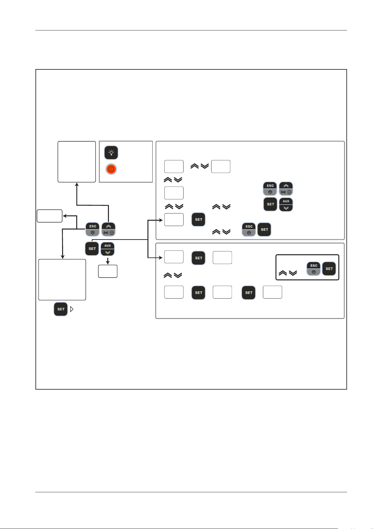
5.1.5. NAVIGATION
Display alarms
if active
Display HACCP alarms
if function active
1 sec
Manual
defrost
3 sec
1 sec
Functions Menu
LOC keypad lock
rHC reset HACCP alarms
rSE activate reduced Set
rPA Pressure switch alarms
rEd disable HACCP
function ON / OFF
Info
System
Turns light on/o
Turns instrument
on / o
1 sec
3 sec
display probe
value
Pb1
-20.6
rtc
18.55
SET
-18.9
USr
inS
display probe
value
Pb2
-20.6
set time and date
modify SetPoint
value
diF
2.0
CPr
- - -
conrm with
SetPoint & Probes
Parameters
modify
value
diF
2.0
conrm with
9MA10258.01 07/2018
29
Page 30

5.1.6. FUNCTIONS MENU AND KEY-ENABLED FUNCTIONS
The Functions menu is used to perform a number of manual functions such as putting the device into stand-by, clearing
pressure switch interventions and clearing HACCP alarms, etc.
Access the Functions menu by pressing the ESC key.
The following table lists the functions, which are all OFF by default.
Display Function description
The UP/ESC/ON-OFF/LIGHT keys and the functions
LOC
OFF
Keypad lock
The DOWN key may be used to view the Setpoint only;
programmed via keys are locked
the value cannot be modified
Only function visible if keypad locked (On)
rEd
OFF
rPA
OFF
rSE
Disables
HACCP alarm
recording
Reset pressure switch
alarm
Reduced set Reduced set
NOTE: the function reverts to OFF status when you exit the
Disables HACCP alarm recording
Clears pressure switch alarm
Functions Menu
OFF
rHC
Reset HACCP alarms
Clears HACCP alarms
May be protected by Password PA3
OFF
All models have the UP key set to display the Alarms Menu.
All models also allow the setting of other keys to activate a specific function as identified by the client.
The parameters for configuring the two keys are:
• H32 = DOWN key configuration
• H33 = ESC key configuration
• H34 = ON/OFF key configuration
• H35 = LIGHT key configuration
The values that can be set apply to these keys and the functions that can be activated are:
Value of
H32/H33/H34/H35
0 = disabled
1 = defrost
2 = Auxiliary
3 = Activate reduced set
4 = Reset HACCP alarms
5 = Disable HACCP alarms
6 = Light
7 = Stand-by
8 = NOT USED
9 = Evaporator fans ON
30
10 = Activate / disable Frame Heater relay
11 = Enable/disable Night And Day functions
12 = deep cooling cycle
13 = Clear voltage drop errors
(Reset Power Failure)
14 = Service stoppage
15 = Activate economy set + Night And Day
Function enabled
9MA10258.01 07/2018
Page 31

5.1.7. PASSWORDS
Password PA1 is disabled by default.
Password “PA1”: allows access to User parameters.
To enable (PA1≠0): press and hold SET for more than 3 seconds. The label USr appears. Press SET again.
Scroll through the parameters using UP and DOWN until you find label PA1, press SET to display its value, change it using
UP and DOWN and save by pressing SET or ESC.
Example with password enabled (PA1≠0): it will be requested before access to the User parameters is granted.
Display description
-17.8
-18.0
USr
PA1
PA1
0
PA1
12
diF
2.0
Press SET for 3 seconds
Label PA1 appears
Press SET
Use UP and DOWN keys to enter the password
In the example the password is 12
Press SET
User menu accessed
The first User parameter appears
If the value entered is incorrect, label PA1 will be shown
again and the procedure must be repeated
Password “PA2”: allows access to Installer parameters.
The example is the same. Note. Password PA2 is set by default to 15
Display description
-17.8
Press SET for 3 seconds
-18.0
USr
Use ‘UP’ and ‘DOWN’ to search for InS
Label USr appears
PA1
9MA10258.01 07/2018
31
Page 32

Display description
inS
Press SET
PA2
PA2
Use UP and DOWN keys to enter the password
0
PA2
In the example the password is 15
Press SET
15
Installer menu accessed
CPr
---
5.1.8. SETPOINT PROGRAMMING
By way of example, we will change the Setpoint value from -18.0 degrees centigrade to -20.0 degrees centigrade.
If the value entered is incorrect, label PA2 will be shown
again and the procedure must be repeated
the first CPr folder appears
Display description
-17.8
Press and release the SET key
-18.0
SEt
-18.0
SEt
-20.0
-17.8
-20.0
The upper display will show SEt, the lower display will
indicate the current setpoint value
Press and release the SET key once more
The upper display will show SEt blinking
Use the UP & DOWN keys to adjust the setpoint value
Press the ESC key several times to return to the normal
display
(or press the SET key to confirm, followed by ESC to exit)
The new Setpoint value is saved and appears on the
lower display
32
9MA10258.01 07/2018
Page 33

5.1.9. VIEWING PROBE VALUES
Display description
-17.8
-20.0
SEt
-20.0
rtc
5.28
Pb1
7.8
Pb2
Press and release the SET key
The upper display will show SEt, the lower display
will indicate the current setpoint value
Use the DOWN key to view the value of probe Pb1
The time is displayed in HACCP models
Use the DOWN key again to view the value of
probe Pb1
Use the DOWN key again to view the value of
probe Pb2
7.8
If H43 is not 0 (probe 3 present)
Pb3
Use the DOWN key again to view the value of
probe Pb3
-18.6
-17.8
Press the ESC key to return to the normal display
Normal display
-20.0
9MA10258.01 07/2018
33
Page 34

5.1.10. How to modify the date and time
Function only available in HACCP models
Display description
-17.8
-20.0
SEt
-20.0
rtc
5.28
rtc
5.28
rtc
Press and release the SET key
The upper display will show SEt, the lower display
will indicate the current setpoint value
Use the DOWN key to display the time
The CLOCK icon will be on
Press and release the SET key.
The CLOCK icon will be on
The hour value will begin to blink
Use the UP & DOWN keys to adjust the hour value
The CLOCK icon will be on
Press and release the SET key
17.28
The CLOCK icon will be on
rtc
17.28
rtc
Use the UP & DOWN keys to adjust the hour value
The hour value has been changed
The minute value begins to blink
Repeat this procedure to adjust the date value
(DAY.MONTH) and YEAR
31.05
In this case the DATA icon (31) is on
rtc
Press the ESC key several times to return to the
normal display
2014
34
9MA10258.01 07/2018
Page 35

5.1.11. Displaying Alarms
Display description
-17.8
Press and release the UP key.
The upper display will show ALr.
-18.0
ALr
nOnE
The lower display will show
a. nOnE if no alarms active
b. SYSt if system alarms present
ALr
SYSt
HACCP models ONLY
ALr
HACP
The lower display will show HACP if HACCP alarms are present
The upper display will show ALr.
NOTE: parameter H50 must = 1
9MA10258.01 07/2018
35
Page 36

5.1.12. System Alarms example
Let us suppose two alarms have occurred,
• one HIGH TEMPERATURE on the cold room probe
• one HIGH TEMPERATURE on probe 3 (parameter H43 different from 0)
Display description
-17.8
-18.0
ALr
SYSt
ALr
HA1
ALr
HA3
Press and release the UP key.
The upper display will show ALr.
The lower display will indicate SYSt
Press and release the SET key.
The upper display will show ALr.
The lower display will show
HA1 HIGH TEMPERATURE alarm on the cold room probe
Use the UP & DOWN keys to view other alarms, if present
In the example, the lower display will indicate HA3 HIGH TEMPERATURE alarm on probe 3
(see para. H43)
Press the ESC key several times to return to the normal display
36
9MA10258.01 07/2018
Page 37

5.1.13. Modifying a parameter
The User parameters USr are not divided into subfolders.
They are always visible by default (access password PA1 is not enabled by default).
The same parameters are also visible in the respective folders ‘Compressor’, ‘Fans’, etc. within the Installer parameters
menu InS. The password is enabled (PA2=15) by default.
NOTE: It is advisable to switch the device off and on again each time the configuration of the parameters is
changed, so as to prevent malfunctions affecting the configuration and/or the current timings.
How to modify a user parameter
Instructions are provided below on how to modify a User parameter
The same procedure applies to Installer (inS) level parameters.
Let us take the dit parameter as our example.
There are no sub-folders at User level. At Installer level the parameter is in the folder containing dEF defrost parameters.
We will now show how to change the value from 6 hours to 8 hours.
Display description
Press and hold the SET key for approx. 3 seconds
-17.8
-20.0
The folder for USr parameters will appear
USr
diF
2.0
Press and release the SET key to access the first
Use the UP & DOWN keys to find the parameter that you
Press and release the SET key.
parameter
The first User parameter appears
wish to modify
Press and release the SET key.
diT
The dit label will blink
6
diT
8
Use the UP & DOWN keys to adjust its value
Press and release the SET key
to confirm the modification.
9MA10258.01 07/2018
37
Page 38

How to modify an Installer parameter
Instructions are provided below on how to modify the same User parameter but via the Installer menu
Let us take the dit parameter as our example.
At Installer level the parameter is in the folder containing dEF defrost parameters.
We will now show how to change the value from 8 h to 6 h.
Display description
Press and hold the SET key for approx. 3 seconds
-17.8
-20.0
The folder for USr parameters will appear
USr
Use the UP & DOWN keys to search for the inS folder
Press and release the SET key.
inS
CPr
---
dEF
---
dit
8
dit
Press and release the SET key to access the first
parameter
The first folder appears
Use the UP & DOWN keys to search for the dEF folder
Press and release the SET key.
The first parameter in the dEF folder will appear
Use the UP & DOWN keys to find the parameter you want
to change
Press and release the SET key.
The dit label will blink
Use the UP & DOWN keys to adjust its value
38
6
Press and release the SET key
to confirm the modification.
9MA10258.01 07/2018
Page 39

6. FUNCTIONS AND REGULATORS
This chapter describes the various functions of the devices.
NOTE: some functions may not be available in certain models.
6.1. SETTINGS
6.1.1. PROBE SETTING AND CALIBRATION
EWRC 300/500/5000 NT have 3 configurable NTC/PTC inputs (Pb1...Pb3).
The temperature probes (Pb1...Pb3) must all be the same type and should be configured via parameter H00, visible at User
level (USr) or inside folder CnF, Installer level (inS)
• H00 = 0 if using PTC probes
• H00 = 1 if using NTC probes (Default)
After installation, the values read by the probes can be corrected/calibrated using the following parameters:
• CA1: probe 1 offset. Positive or negative value to be added to the value read by Pb1 (Range: -30.0...30.0)
• CA2: probe 2 offset. Positive or negative value to be added to the value read by Pb2 (Range: -30.0...30.0)
• CA3: probe 3 offset. Positive or negative value to be added to the value read by Pb3 (Range: -30.0...30.0)
6.1.2. DISPLAY SETTINGS
At User level (Usr) or inside the diS folder at Installer level (inS) you will find the parameters used to set the temperature
readout, decimal point usage, unit of measure and display during defrost.
• ndt: (USr/inS) enables/disables decimal point display
(with resolution of one-tenth of a degree; e.g.: 10.0°C)
Display with decimal point is only possible within the range of values from -99.9°C to 99.9°C
• ndt = y displays read values with decimal point (default);
• ndt = n displays read values without decimal point
NOTE: enabling/disabling the decimal point only affects the on-screen display of values.
The controller will continue to perform calculations with decimal point.
• ddL: (USr/inS) sets the type of display during and up to the end of defrost
• ddL = 0 displays the probe value (default)
• ddL = 1 continues to display the value read by the probe at the start of defrosting
• ddL = 2 displays the fixed label dEF
• dro: (inS) sets temperature display to °C or °F.
• dro = 0 display in °C (default)
• dro = 1 display in °F
NOTE: switching between °C and °F DOES NOT modify the values of temperature parameters
(e.g. setpoint=10°C becomes 10°F).
This means that the maximum and minimum limits of parameters as absolute values
are the same for both units of measure and hence the ranges are different.
• ddd: (inS) establishes the value to be shown on the upper display.
All other display and adjustment modes are the same.
• ddd = Set displays the Setpoint value
• ddd = Pb1 displays the values read by Pb1 (default)
• ddd = Pb2 displays the values read by Pb2
• ddd = Pb3 displays the values read by Pb3
9MA10258.01 07/2018
39
Page 40

6.2. FUNCTIONS
6.2.1. UPLOAD, DOWNLOAD, FORMAT
Description
The Unicard/CopyCard must be connected to the (TTL serial port and allows the rapid programming of instrument
parameters.
DOWNLOAD from reset operating mode: at power-on, if the Unicard/CopyCard is inserted in the device, the controller
automatically downloads data.
After connecting the Unicard/CopyCard with the instrument switched off and on completion of the lamp test, one of the
following labels will be displayed:
• dLY if the operation was successful
• dLn if the operation was not successful
After about 5 seconds, the display will show the probe or set point value, depending on the default settings.
NOTE: once the download has been completed successfully, the controller will start to work with the new map loaded.
Operating mode: access “Installer” parameters by entering the password “PA2” if enabled (PA2≠0), scroll through the folders
using UP & DOWN until the folder “FPr” appears. Select it using SET, scroll through the parameters using UP & DOWN and
then select one of the functions by pressing SET:
• UL (Upload): With this function, the programming parameters are uploaded from the instrument to the card.
If the operation is successful, the display will show “y”, otherwise it will show “n”.
• Fr (Format): This command is used to format the copy card (which is necessary when using the card for the first
time).
NOTE: the use of the Fr parameter deletes all data present and this operation cannot be reversed.
• Download: Connect the Unicard/CopyCard when the instrument is switched off. At power-on, data will
automatically start downloading from the Unicard/CopyCard to the instrument. At the end of the lamp
test, the display will show “dLy” if the operation was successful and “dLn” if not.
NOTE: before Uploading or Downloading a map, make sure that communication
with the supervisor (PC with Televis, TelevisGo system, etc.) has been cut off.
This means you should make sure that the RS-485 is disconnected from the instrument or that Supervision system
acquisitions have been stopped.
Parameters
The parameters that control this function are:
Label Description
UL
Transfer of programming parameters from device to Unicard/CopyCard
COLDFACE Unicard/CopyCard
dL
Transfer of programming parameters from Unicard/CopyCard to device
Unicard/CopyCard COLDFACE
Fr Unicard/CopyCard formatting. Erases all data on the UNICARD/CopyCard
40
9MA10258.01 07/2018
Page 41

6.2.2. UNICARD
The Unicard lets you download/upload a parameter map from/to a controller, in the same way as the CopyCard.
It is a versatile tool that also allows you to quickly and easily customise devices.
It differs from the Copy Card in the following ways:
1) it can be connected to a computer via USB
2) it can be plugged into a USB socket or USB battery, to power the device directly during upload/download.
The UNICARD can be powered in the following ways:
A) Cabinet powered
EWRC300/500/5000 NT
010 011010100111010100010100110 0110101001110101000101010100
DISPLAY
B) Site powered
9MA10258.01 07/2018
010 011010100111010100010100110 0110101001110101000101010100
EWRC300/500/5000 NT
DISPLAY
41
Page 42

6.3. BOOT LOADER FIRMWARE
The device is equipped with a Boot Loader, so it is possible to update the Firmware directly on site.
Updating may be carried out using UNICARD or CopyCard (CopyCard).
Updating procedure:
• Connect the UNICARD/CopyCard equipped with the application;
• Power the device if it is off, otherwise switch it off and on again
NOTE: the UNICARD/CopyCard can be connected even with the instrument powered.
• Wait until the LED for the UNICARD/CopyCard is blinking (operation in progress);
• The operation will be concluded when the LED for the UNICARD/CopyCard is:
• ON: operation concluded correctly;
• OFF: operation not performed (application not compatible...)
NOTE: the LED display is only provided for UNICARDS produced from week 18-12 onwards.
42
9MA10258.01 07/2018
Page 43

6.4. COMPRESSOR
SEt
The compressor is controlled by the device’s relay. It will be switched on or off depending on:
• the temperature status readings from the cold room probe
• the temperature control functions set
• the defrost/dripping functions (see Defrost chapter)
6.4.1. Compressor configuration
See the wiring diagrams for details of how to connect the compressor to the device
Relay polarity is fixed.
NOTE: you MUST check the Compressor digital output (relay) association by setting parameter H2x accordingly.
NOTE: By default H21 = 1 (compressor)
6.4.2. Second compressor configuration
Coldface offers the option of using a second compressor
NOTE: you MUST check the Compressor 2 digital output (relay) association by setting parameter H2x accordingly.
Example H25 = 10 (compressor 2).
NOTE: to prevent the two compressors from starting up with an insufficient interval in between, an activation delay can be
set for the second compressor using dSC.
6.4.3. Compressor operating conditions
Compressor operation
The regulator is active when:
• the device is ON
• there is not an alarm E1 indicating control probe fault
• the time set in parameter OdO has elapsed
• a defrost cycle is not underway (except in FREE mode)
(There is a fixed interval of one second between the request and activation of the relay)
The parameters that control this regulator are:
• the setpoint that can be set via the keypad, with a range from minimum to maximum setpoint.
• the differential
The diagram below indicates the compressor activation mode for cooling based on parameters SEt and diF > 0.
ON
OFF
°C
9MA10258.01 07/2018
ON
OFF
diF
°C
43
Page 44

6.5. COMPRESSOR/GENERAL PROTECTIONS
Description
If the cold room probe is in error E1 the output relay configured as compressor/general regulates in accordance with the
times set in parameters Ont and OFt.
The first time to consider is Ont.
If Ont >0 the protection programmed in parameters
dOn-dOF-dbi (see safety compressor times).
NOTE: remember that parameter OdO inhibits the activation of all outputs commanding a relay for its entire duration
(compressor/general, defrost, fans), excluding buzzers or alarm relays.
Operating conditions
The table below lists the ways the compressor relay output can be managed:
Ont OFt Compressor OUT
0 0 OFF
0 >0 OFF
>0 0 ON
>0 >0 Duty-cycle
If Ont > 0 and OFt = 0 the compressor regulator entrusts relay deactivation to the safety protection CAt.
If Ont > 0 and OFt > 0: the compressor regulator activates in operating cycle mode irrespective of the values read
by the probes (cold room probe failure) and of requests from other loads (Duty-cycle mode).
If the cold room probe is working properly, Duty-cycle mode does NOT activate as it does not have priority over normal
compressor regulator settings.
The following diagram shows the Duty-cycle operating mode, based on parameters Ont and OFt > 0:
ON
OFF
Ont OFt
Ont OFt
°C
44
9MA10258.01 07/2018
Page 45

6.5.1. Compressor safety timings
IN
OUT
IN
Compressor on-off operations must respect the safety times that you can set using the special parameters as
described below.
The compressor icon will flash to indicate when a compressor activation request has been received but a safety
protection exists.
A safety time (compressor On... Off safety time) regulated by the parameter dOF must be respected between a
switch-off and switch-on of the same compressor. This waiting time also occurs at switch-on of the device.
A safety time regulated by the parameter dbimust be respected between one switch-on and the next.
The safety time set in parameter dOn must elapse between a compressor start-up request and actual start-up.
Times set with parameters dOn, dOF and dbi, if active, are not accumulative but parallel.
The following diagram illustrates the operation of the compressor protection with parameters dOn, dOF, dbi set
where:
IN Input status for compressor regulator.
OUT Output status for compressor regulator.
ON
OFF
ON
OFF
dOn
dbi
dOF
dOn
dOF
dbi
NOTE: See the chapter entitled Compressor Function During Defrost for other safety measures and compressor timings.
Maximum timer period
The maximum compressor activation time before its deactivation can be set via the parameter CAt.
Minimum timer period
The minimum compressor activation time before its deactivation can be set via the parameter Cit.
9MA10258.01 07/2018
45
Page 46

User parameters
The parameters that manage this regulator are:
Label Description
Ont Compressor output ON time in the event of a faulty Pb1 probe
OFt Compressor output OFF time in the event of a faulty Pb1 probe
dOn Compressor output activation delay from request
dOF Compressor output activation delay from shutdown
dbi Delay between two consecutive starts of the compressor output
OdO Output activation delay from power-on
Cit Minimum compressor output activation time
CAt Maximum compressor output activation time
6.6. DEFROST/DRIPPING
6.6.1. Defrost type and activation
Defrost is used to stop ice from forming on the surface of the evaporator.
Its activation can be:
• automatic, in one of the following modes selected via dCt:
• compressor hours (Digifrost);
• device hours;
• compressor stop;
• via clock (see corresponding paragraph under RTC);
• via digital input (DI);
• via key;
• remotely.
The type of defrost can be selected via the parameter dtY and can be:
1. defrost with electric heaters;
2. inverse;
3. FREE
Dripping
On completion of defrost, given that there will be water on the evaporator, it is better not to start “cooling” right away as this
would ruin the effect of the defrost by creating ice immediately.
The dripping interval is regulated via parameter dt.
Defrost conditions and operation
Defrosting is enabled if:
• the evaporator temperature, read by probe 2, is lower than the defrost end setpoint configured via parameter dSt
• manual defrosting has not already been activated, in which case the request for automatic defrost will be cancelled.
Defrost requests can be made in the following ways:
Controller power-on if parameter dPO (defrost at power-on) is programmed accordingly.
Time intervals if dit > 0 whenever the defrost time interval set in parameter dit elapses.
Manually
(via key)
External request via
digital input (DI)
HACCP models also offer the following mode:
Time
46
by pressing the UP key
The cycle will not start if OdO≠0; the request will be refused and the display will flash three
times to indicate that defrost is impossible.
If the digital input (DI) is suitably configured.
Activation via digital input (DI) respects the protections of the automatic cycle.
The cycle will not start if OdO≠0; the request will be refused and the display will flash three
times to indicate that defrost is impossible.
if dit = 0 and dCt=3 with rtc function (real time clock).
At the times set in parameters dE1...dE8 (dd folder)
9MA10258.01 07/2018
Page 47

6.6.2. Automatic defrosting
The defrost cycle is programmed to start at intervals.
NOTE: To disable the automatic cycle, set dit=0.
If dit>0, the defrost cycles will be run at fixed intervals, as indicated in parameter dit and the interval time is counted as
follows:
Par. Value U.M. Description Notes
In this case, the counter runs only if the compressor is on.
dCt
0 num
1 num
Hours of
compressor
compressor
(DIGIFROST
method®)
Device running
time
A new count starts when the defrost interval elapses and a new defrost cycle starts
if conditions permit.
NOTE: compressor running time is counted
separately from the evaporator temperature.
If the evaporator probe is missing or faulty, the count
continues for the time the compressor is on.
The defrosting interval is counted continuously when the device is on and starts at
each power-on.
A defrost cycle starts when the defrosting interval elapses (indicated by dit) if
conditions permit and the controller immediately starts counting a new defrosting
interval.
2 num Compressor stop
3 num
NOTE: regardless of how the interval is counted, the following conditions apply:
If parameter OdO is underway or the temperature read by the evaporator probe is higher than dSt, then defrost will not be
permitted: a new interval will be counted and only at the end of this subsequent count will conditions be tested for the start of
a defrost cycle.
RTC
(clock)
Each time the compressor stops, a defrost cycle is run according to the mode set
in parameter dty.
The clock can be used to set:
• defrost times (6 bands for weekdays and 6 bands for weekends/holidays),
• regular defrosts (every n days)
• daily events (1 event for weekdays and 1 event for weekends/holidays)
Time band defrosts and periodic defrost are mutually exclusive functions (they
cannot be activated simultaneously).
If defrost by RTC has been enabled and the clock has failed, the defrost will run
according to the mode set in dit (provided the value is ≠ 0).
6.6.3. Manual defrost
Press and hold the manual defrost key ESC (or from digital input (DI) if appropriately configured H11...H13 = 1), the device
enters defrost. Procedures for the activation of this defrost cycle are the same as for external defrost.
The defrosting interval will now be counted as described for Automatic Defrost (time dEt is not cleared, it continues).
If the conditions for defrost activation are not present, i.e.:
• the time set in parameter OdO has not elapsed
• the evaporator temperature is higher than the value set in parameter dSt
this will be indicated on the display (screen flashes three times) and the defrost will stop.
Manual defrost is always enabled except when dit = 0.
9MA10258.01 07/2018
47
Page 48

6.6.4. External defrost
OUT
IN
OUT
OUT
dit
If the Digital Input is configured for this function (if H11...H13 = 1) and if conditions permit, defrost can be requested and the
corresponding regulator activated.
Time graphs for signals in each of the various function modes are presented below.
NOTE: Defrost activation occurs when the signal is toggled and the polarity can be selected.
Hence you can only activate a defrost, NOT stop one that is underway.
Defrost or dripping currently underway and the defrost or dripping interval count cannot be suspended.
IN (Digital Input) Input status for defrost regulator, with activation from Digital Input.
OUT (Defrost) Output status for defrost regulator.
DurDI Digital Input duration.
NOTE:
ON
OFF
dSt indicates end defrost time when Setpoint temperature reached and dEt indicates end of defrost
due to timeout.
Dur.DI
ON
OFF
IN
ON
OFF
ON
OFF
IN
ON
OFF
ON
OFF
(dSt)
(dSt)
(dSt)
dEt
dEt
dEt
Dur.DI
Dur.DI
(dSt)
dEt
Dur.DI
(dSt)
dEt
48
9MA10258.01 07/2018
Page 49

6.6.5. Defrost WITH REMOTE START/STOP
If the Digital Input is configured for this function (if H11...H13 = ±22) defrost with start/stop is activated
from remote.
The defrost is switched on when the digital input becomes active. Vice versa, when the digital input is disabled, the defrost
ends.
If the automatic defrost is also active, the two functions will proceed in parallel. In this case, the defrost interval
set in the parameter dit will be reset when the remote defrost is activated (digital input).
Having ended the remote defrost, the dripping function will be activated if dt > 0.
The conditions for activation are:
• Defrost probe present and temperature lower than dSt;
• Defrost not inhibited by an alarm.
The defrost will not be activated if the following conditions are present:
1. Defrost end probe present and temperature higher than dSt;
2. Alarm condition inhibiting the defrost,
The defrost may end before the defrost is disabled from the digital input (DI) if:
• dEt ends the count;
• Defrost probe present and temperature higher than dSt;
• Alarm condition ending the defrost early.
To manage the activation delays of the digital inputs DI1 and DI2 separately:
• Set dAd = 0;
• Add a delay using parameters O1i (to delay the activation of digital input DI1) and O2i (to delay the activation of digital
input DI2), the delay of the digital input DI3 can be set using parameter di3.
NOTE: If dAd ≠ 0, any delays set in O1i and O2i will not be considered by the instrument.
User parameters
Label Description
dAd Delay activating digital input DI1 and digital input DI2.
O1i Delay activating digital input DI1
O2i Delay activating digital input DI2
di3 Delay activating digital input DI3
9MA10258.01 07/2018
49
Page 50

6.7. DEFROST MODE
6.7.1. Defrost with electric heaters
Defrost with electric heaters is configured via parameter dtY = 0.
The compressor remains stopped for the duration of the defrost cycle and the relay configured as defrost regulator output,
to which the electric heaters are connected, activates. On completion of defrost, the electric heaters are switched off and the
compressor remains off for the dripping time set in parameter dt, if it is not equal to zero.
Defrost ends due to:
Evaporator Probe End of defrost description
Evaporator Probe
ABSENT
Evaporator Probe
PRESENT
NOTES:
• If dSt intervenes before dEt, dripping (dt and Fdt) aligns with dSt.
• If Fdt < dt then Fdt = dt.
• During defrost, fans are OFF if parameter dFd is set accordingly, otherwise they will behave as set for the fan regulator.
Due to timeout set in parameter dEt (defrost timeout)
Temperature setpoint for the end of defrost set in parameter dSt reached.
If this setpoint is not reached within the time set in parameter dEt (defrost timeout), the defrost
will end due to timeout.
The operating diagram is as follows:
ON
OFF
ON
OFF
ON
OFF
Key:
Output status for Compressor regulator
(dSt)
dEt
dt
Fdt
50
Output status for Defrost regulator
Output status for Evaporator Fan regulator
9MA10258.01 07/2018
Page 51

6.7.2. Inverse defrost
Defrost Output
Defrost Output
Hot gas defrost is configured by setting parameter dtY = 1.
The compressor stays on for the entire duration of the defrost cycle and the relay configured as defrost regulator output, and
that the solenoid valve is connected to, activates.
On completion of the defrost cycle, the valve relay is de-energised and the dripping phase set in parameter dt (if not equal to
zero) is interrupted. The compressor relay is once again controlled by the compressor regulator.
Defrost ends due to:
Evaporator Probe End of defrost description
Evaporator Probe
ABSENT
Evaporator Probe
PRESENT
NOTE: Parameters dOn, dOF and dbi still have priority.
NOTES: • If dSt intervenes before dEt, dripping (dt and Fdt) aligns with dSt.
• If Fdt < dt then Fdt = dt.
• During defrost, fans are OFF if parameter dFd is set accordingly, otherwise they will behave as set
for the fan regulator.
The operating diagram is as follows:
Due to timeout set in parameter dEt (defrost timeout)
Temperature setpoint for the end of defrost set in parameter dSt reached.
If this setpoint is not reached within the time set in parameter dEt (defrost timeout),
the defrost will end due to timeout.
Compressor
Compressor
Defrost
request
Defrost
request
tcd>0
Defrost
Defrost
Defrost
Draining
dtdEt
Defrost
Draining
end
end
Example tcd>0
Defrost Request
= Start defrost request
Defrost = Defrost time
Dripping = Dripping time
Defrost end = End of defrost
Compressor = Compressor
Defrost Output = Defrost output
Example tcd<0
Defrost Request
= Start defrost request
Defrost = Defrost time
Dripping = Dripping time
Defrost end = End of defrost
tcd<0
9MA10258.01 07/2018
Compressor = Compressor
Defrost Output = Defrost output
dtdEt
51
Page 52

6.7.3. Double evaporator defrost
The defrost for a second evaporator can be controlled via the probe configured as second evaporator.
Configure a relay output (see configuration parameters H21…H25) as a defrost relay for evaporator 2.
To enable this function, you need to:
• set probe Pb3 to control defrost evaporator 2 mode (parameter H43).
• configure a relay output (see configuration parameters H21…H25) as a defrost relay for evaporator 2.
• Define defrost mode by setting parameter H45.
Input mode
A double evaporator defrost can take place in three different ways on the basis of parameter H45, as described below:
• H45=0: Defrost is enabled only when the temperature of evaporator 1 is lower than the value set in parameter dSt.
• H45=1: Defrost is enabled when the readings from at least one of the two probes is below its defrosting end temperature
(dSt for evaporator 1 and dS2 for evaporator 2)
• H45=2: Defrost is enabled when both probe values are below the corresponding end of defrost setpoints (dSt for evaporator 1 and
dS2 for evaporator 2)
The probe error condition is considered as a probe calling for defrost.
The defrost for every single evaporator ends when the following conditions have been met:
• the dEt/dE2 timeout period has elapsed
• the dSt/dS2 temperature has been reached
Ending mode
Defrost in the case of a double evaporator takes place when both probe values have reached or exceeded the relative end of defrost
setpoints (dSt for evaporator 1 and dS2 for evaporator 2)
If one or both probes are in error, the end of defrost will take place due to timeout.
In any case
If there are no conditions for performing the defrost the request will be cancelled.
The defrost for a single evaporator will end when the corresponding probe reaches or exceeds the defrosting end temperature or when
the timeout period begins.
Dripping begins when both defrosts have ended.
If one or both probes are in error, the defrost for the corresponding evaporator will end due to timeout. Onset is allowed as if the
corresponding temperature is lower than the corresponding setpoint (dSt or dS2).
If the probe is not configured to be the probe for the second evaporator (H43 ≠2), the defrost for the second evaporator may take
place if a digital output is configured to control defrost on the second evaporator (H21..H25 = 9). In this case consent for defrost will be
granted, as if the probe temperature (evaporator 2) < dS2 and the output takes place due to timeout. The fan regulator is not affected.
52
9MA10258.01 07/2018
Page 53

User parameters
The parameters that manage this regulator are:
Label Description
dty Selects defrost type
dit Time interval between 2 consecutive defrost cycles
dCt Selects the count mode for the defrost interval
dOH Defrost cycle activation delay after request
dEt Defrost timeout evaporator 1. Determines the maximum defrost duration
dE2 Defrost timeout evaporator 2. Determines the maximum defrost duration
dSt Defrost 1 end temperature - determined by evaporator probe 1
dS2 Defrost 2 end temperature - determined by evaporator probe 2
dPO Determines whether the instrument must enter defrost mode at power-on
Fdt Fan activation delay after a defrost cycle
dt Dripping time
dFd Allows exclusion of the evaporator fans to be selected or not selected during defrosting.
dAO Temperature alarm disabling time after defrost cycle
dAt Alarm signalling end of defrost due to timeout
ddL Display mode during defrost cycle (lock display.)
Ldd Timeout value for display unlock - label dEF
Summary table
Defrost on evaporator 1
Defrost START Defrost END
If H45=0
If H45=1
If H45=2
Probe Pb3 (evaporator 2) (evaporator 1) temperature
< dSt
Probe Pb3 (evaporator 2) (evaporator 1) temperature
< dSt
Probe Pb3 (evaporator 2) (evaporator 1) temperature
< dSt and
Probe Pb3 (evaporator 2) (evaporator 1)
temperature > dSt
or if
Probe Pb3 (evaporator 2) (evaporator 1)
temperature <dSt due to time-out
or if probe Pb2 in error due to timeout
Probe temperature (evaporator 2) < dS2
Note: if the probe is in error or H43 ≠2 and a digital output is configured as a regulator for the second evaporator, the
following condition applies: Probe temperature (evaporator 2) < dS2
Defrost on evaporator 2
Defrost START Defrost END
Probe Pb3 (evaporator 2) (evaporator 1) temperature
If H45=0
< dSt
and Probe temperature (evaporator 2) < dS2
If H45=1 Probe temperature (evaporator 2) < dS2
Probe Pb3 (evaporator 2) (evaporator 1) temperature
If H45=2
< dSt
Probe 3 temperature (evaporator 2) > dS2
or if
Probe temperature (evaporator 2) < dS2 due to
timeout
or if probe in error due to timeout.
and Probe temperature (evaporator 2) < dS2
Note: if the probe is in error or H43 ≠2 and a digital output is configured as a regulator for the second evaporator, the
following condition applies: Probe temperature (evaporator 2) < dS2
Dripping
Drip cooling START Drip cooling END
End of defrost for both evaporators if defrosting takes place for
both evaporators, otherwise end of the only defrost in progress
9MA10258.01 07/2018
Unchanged
53
Page 54

6.8. EVAPORATOR FANS
6.8.1. Evaporator fan operating conditions
The regulator is active when:
• the time set in parameter OdO has elapsed.
• the temperature of the evaporator probe, if present, is between the values of parameters Fot and FSt
• during defrost it is not excluded by the parameter dFd (dFd = y).
• dripping is not active (dt).
• the fan delay is not active after defrost (Fdt).
The request to switch fans on or off can be made in the following ways:
• by the compressor regulator to help in the “cooling” process (temperature control mode.)
• by the defrost regulator to check and/or limit the diffusion of hot air.
FCO Compressor ON Compressor OFF
0 THERMOSTAT CONTROLLED OFF
Probe present and
working
Probe present but in error
Probe absent
* see paragraph “Fan operation with probe Pb2 absent” (H42 ≠ 0).
** Normal Duty-Cycle operation reversed (OFF cycle - ON cycle)
1 THERMOSTAT CONTROLLED THERMOSTAT CONTROLLED
2 THERMOSTAT CONTROLLED THERMOSTAT CONTROLLED
3 THERMOSTAT CONTROLLED DUTY-CYCLE*
4 THERMOSTAT CONTROLLED DUTY-CYCLE* **
0 DUTY-CYCLE OFF
1 ON OFF
2 DUTY-CYCLE DUTY-CYCLE
3 DUTY-CYCLE DUTY-CYCLE
4 DUTY-CYCLE DUTY-CYCLE
0 ON OFF
1 ON ON
2 DUTY-CYCLE* DUTY-CYCLE*
3 ON DUTY-CYCLE*
4 ON DUTY-CYCLE* **
54
9MA10258.01 07/2018
Page 55

The graphs below illustrate fan operation on the basis of the FCO value.
In the graphs, we can see that:
FCO = 0
FCO = 2
FCO = 4
COOL
PROBE OK
PROBE KO
COOL
PROBE OK
PROBE KO
COOL
PROBE OK
PROBE KO
Fon/FoF
Fon/FoF
Fon/FoF
Fon/FoF
COOL
PROBE OK
FCO = 1
PROBE KO
COOL
Fon/FoF
PROBE OK
FCO = 3
PROBE KO
Fon/FoF
Key:
COOL Cooling
Probe OK Fan operation with the probe present and working
Probe KO Fan operation with the probe present but in error
6.8.2. Fan operation in temperature control mode
During “cooling”, the fans operate as shown in this diagram:
Thermostat control of fans takes place at the values set in parameters
• FSt (fan disabling temperature) and FAd (fan differential).
• Fot (fan start temperature) and FAd but with the sign inverted.
By default, the fan disabling temperature, set by parameters FSt (fan disabling temperature) and FAd (fan differential), is an
absolute value, as FPt = 0 (actual temperature value).
Depending on the parameter FPt, the fan disabling temperature set at parameter FSt can be absolute (actual temperature
value) or relative (value to add to the Setpoint SEt).
Depending on the parameter FPt, the fan start temperature set at parameter Fot can be absolute (actual temperature value)
or relative (value to add to the Setpoint SEt).
NOTE: if as an absolute value the parameter Fot is greater than FSt the fans will be excluded
Around the fan start temperature (-50°C by default) the differential will always take account of the differential parameter FAd
but with the sign inverted (negative side). Fan stop in Fot, and activation at value (Fot + FAd).
The fan regulator operates as indicated below:
9MA10258.01 07/2018
55
Page 56

ON
OFF
FAd
FSt
°C
(Pb3)
6.8.3. Fan operation in Duty-Cycle mode
For Duty-cycle operation, parameters Fon and FoF must be set accordingly;
The fans operate as follows:
DUTY-CYCLE
Fon FoF Fan operation
0 0 OFF
0 ≠0 OFF
≠0 0 ON
≠0 ≠0 DUTY-CYCLE
The fan regulator will operate in Duty-cycle mode as illustrated below:
DUTY-CYCLE
ON
OFF
Fon
FoF Fo n
FoF
56
9MA10258.01 07/2018
Page 57

6.8.4. Fan operation in defrost
During defrost, the fans operate as shown in this diagram
dFd = n: the fans are not excluded during defrost
(see parameters FCO, Fon, FoF)
TEMPERATURE CONTROL / DUTY-CYCLE
dFd = y: exclusion of fans during defrost OFF
Thermostat control of fans takes place at the values set in parameters:
• FSt (fan disabling temperature) and FAd (fan differential).
NOTE: during defrost with electric heaters, the compressor is OFF but the fans work as if the compressor was still ON, unless they
have been disabled during defrost (see parameter dFd).
When the evaporator fans are enabled in defrost (dFd = n) and regulate the evaporator probe Pb2 in thermostat controlled mode, when
the latter enters error “E2” during defrost, the fans must always be ON, regardless of the values set via the Duty-cycle.
Fan operation without probe
If parameter H42 = n (probe Pb2 absent), depending on the FCO value and the status of the compressor, the fans may assume the
status “On”, “Off”, “Duty-cycle”.
The parameter FCO will determine the operating mode of the evaporator fans during the DAY phase and the NIGHT phase.
The following is an example of fan operation on the basis of the value set for FCO.
COOL
FCO = 0
FCO = 1
FCO = 2
FCO = 3
FCO = 4
Fon/FoF
Fon/FoF
Fon/FoF
9MA10258.01 07/2018
57
Page 58

6.8.5. Fan function during dripping
If parameter dt ≠ 0 (dripping time), the fans will stay OFF for the time set in this parameter.
See “Defrost with electric heaters”.
Note that if Fdt (fan delay time) is greater than dt (dripping time) the fans stay OFF for the time set in Fdt rather than dt
(e.g. whichever timing is longer will be applied).
6.8.6. Post-ventilation
Parameter FdC delays the switching off of the fans after the compressor has stopped (increasing efficiency of the system by
making better use of inertia). Post-ventilation must be active with any FCO value and without a configured probe.
If FdC = 0 the function is disabled.
NOTE: Post-ventilation does not have priority over the delay set by parameter dcd.
User parameters
The parameters that manage the fan regulator are:
Label Description
FPt
FSt Evaporator fan disabling temperature
Fdt Evaporator fans delay after defrost cycle
dFd Evaporator fans disabling during defrost time
FCO Evaporator fans operating mode
FAd Evaporator fans activation differential
dt Dripping time
FdC Evaporator fans switch-off delay after compressor deactivation
Fon Evaporator fans ON time in duty-cycle mode
FoF Evaporator fans OFF time in duty-cycle mode
Characterises parameter “FSt” which can be expressed either as an absolute value or relative to the
setpoint
58
9MA10258.01 07/2018
Page 59

6.9. DEEP COOLING CYCLE - DCC
DI1, DI2, UP
Description
This regulator ensures that the compressor regulates the setpoint dCS, with differential equal to the value set via parameter
diF. When the DCC (Deep Cooling Cycle) activates, the interval between defrost cycles is cleared and defrosts are disabled.
Ending of the DCC is time-based, by setting the parameter tdc≠0, or when the setpoint dCS if tdc = 0.
When a DCC has ended and once the time set in parameter dcc has elapsed, a defrost cycle is forced and the counters
restart for the interval between defrost cycles (value set via parameter dit). If dcc=0 defrost begins at the end of the DCC.
During the DCC the temperature alarms are disabled.
Normal temperature alarm management is restored at the end of the DCC, when the temperature value read by probe Pb1
reaches the regulation setpoint value SEt.
Operating conditions
The Deep Cooling Cycle will be activated via Digital Input or via a suitably configured key.
In the event of a probe error and/or power failure, the Deep Cooling Cycle is stopped and standard controller function
restored.
If the dCS parameters are changed, tdc and dcc the functioning of the Deep Cooling Cycle is recalculated with new set
values.
NOTE: After a Deep Cooling Cycle, the dcc time must elapse before a new cycle can begin.
DOWN, ESC
ON
OFF
°C
(Pb1)
SEt
dCS
tdC
User parameters
The parameters that manage the fan regulator are:
Label Description
dCS Deep Cooling set point
tdc Deep Cooling Time
dcc Delay Defrost after Deep Cooling
6.10. PREHEAT
The preheating phase is linked to a suitably configured digital input (H11... H13 = ±12).
In the period when the preheat output is active:
• the compressor output will be forced OFF;
• the compressor icon will flash.
The Preheat only affects defrosting in applications that require the use of the compressor (dty= 1 and dty= 2).
9MA10258.01 07/2018
59
Page 60

6.11. PRESSURE SWITCH
This regulator performs diagnostic procedures on an activated digital input by assigning the value ±11 (General pressure
switch), ±09 (Minimum pressure switch) or ±10 (Maximum pressure switch) to one of the parameters H11...H13.
If a pressure switch input is activated, power to the compressor loads is immediately cut off, the corresponding alarm icon
lights up to provide a visual warning and the alarms folder ALr is also displayed. The folder contains labels with the number
of pressure switch activations (up to the maximum value set in parameter PEn):
• P01, P02, ...P0n... for general pressure switch
• H01, H02, ...H0n... for maximum pressure switch
• L01, L02, ...L0n... for minimum pressure switch
If the number of activations exceeds the maximum number defined by parameter PEn within a time less than the value of
PEi, the following conditions occur:
• The compressor, fan and defrost outputs are disabled
• in the alarms folder ALr label PA , LPA or HPA are displayed (general, minimum or maximum pressure switch
respectively).
• The alarm relay comes on (if configured).
NOTE: 1) if the number of activations exceeds the number set in PEn in the PEI time, the alarm is automatically reset.
2) the input must be:
• closed on itself if unused and the input is active when normally closed;
• open if unused and active when normally open;
• deactivated via digital input configuration parameter.
NOTES: 1) Once it has entered alarm status, the device must be switched off and on again, or reset using the rPA key in
the functions menu.
2) If parameter PEn = 0, the function is disabled and alarms and counters are also disabled.
3) The pressure switch alarm is not stored in EEPROM
4) During the pressure switch activation period the defrost interval count runs as normal.
Operating conditions
The number of pressure switch errors is counted using a FIFO method. The time interval PEi is divided into 32 parts; the
counter is incremented by one unit if there are one or more activations during one part of the entire interval PEi.
Two operating examples are given below: In both cases, suppose that PEi = 32’ (equal to 32’/32 = 1 minute) and PEn = 7.
Example 1: ALARM SIGNALLED. The interval for storing activations is 1 minute: all activations within that minute
are counted as a single activation and the alarm is activated when the sampling
interval has elapsed. In this example the pressure switch alarm is signalled
because there have been 7 activations during the 32’ time window.
Example 2: ALARM NOT SIGNALLED In this example the alarm is not activated because during the 32’ time window
the number of activations set in parameter PEn was not reached. In practice
the time window is a rolling window and all activations that are outside of it are
deleted: the reference point is the last activation and the time PEi is subtracted
from that point to establish how many activations are included in the count.
Example 1
30’’ 30’’
6
ALARM ALERT
7
4’1’
Time
1
0
The time between the 1st and 7th activation is 11' < PEI (32')
2
2’ 2’ 1’ 1’
3
4 5
Example 2
1
0
The time between the 1st and 7th activation is 33' < PEI (32')
2
2’ 2’ 1’ 1’
3
4 5
6
30’’ 30’’
NO ALARM ALERT
7
26’1’
Time
The parameters that manage the pressure switch regulator are:
60
Label Description
PEn Number of errors allowed per general/maximum/minimum pressure switch input
PEI General/minimum/maximum pressure switch error count interval (in 32 parts)
9MA10258.01 07/2018
Page 61

6.11.1. AUXILIARY OUTPUT (AUX/LIGHT)
DI
Description
If one of the parameters H21...H25 is set to the value H2x=5, it anticipates the relay control as AUX and, by pressing the associated key
H32...H35 which must be set to the value H3x=2, the relay is activated if it was off previously and vice-versa.
The on/off status is saved in non-volatile memory hence when power returns after a blackout, the device will restart in the status that was
active prior to the blackout.
If one of the parameters H11...H13 is set to the valueH11...H13=±3, it anticipates the AUX relay control by the digital input; in this case
the relay will mirror the status of the input. In this case, on/off status is not saved in non-volatile memory.
NOTE: the meaning of the digital input (DI) must always remain the same: for example, if the relay is activated by digital input (DI) and
switched off by key, when the digital input (DI) is reset to the starting position, the relay does not change status (since it was already
de-energised by key).
With the instrument OFF, if set accordingly, only the digital input (DI) and the associated key can change the status of the output.
Operating conditions
The regulator is activated by:
• Key
• Function
• Digital Input
if configured accordingly.
The regulator is not active when:
Condition AUX output status
during start-up OFF
during stand-by status depending on parameters H06 and H08
ON
OFF
ON
OFF
RL
ON
OFF
User parameters
The parameters that manage the auxiliary (AUX) output regulator are:
Label Description
H11...H13 Configuration of digital input 1...3 / Polarity
H21...H25 Configuration of digital output 1...5
H32...H35 Configuration of DOWN, ESC, ON/OFF, LIGHT key
9MA10258.01 07/2018
61
Page 62

6.12. DOOR/EXTERNAL ALARM MANAGEMENT
The door switch input is associated to an appropriately configured digital input (H1x = ±4).
By controlling the opening of the door, it is possible to disable the compressor output and/or the fans.
It is also possible to associate a deactivation delay with the compressor output by means of parameter dCO.
If the door is opened during a defrost cycle, the cycle is not shut down.
The values that can be set for the parameters involved are:
dod: Door switch switches off loads on digital input (DI) command
• 0 = function disabled
• 1 = disables fans (FAN)
• 2 = disables the compressor (COMP)
• 3 = disables the compressor (COMP) and fans (FAN)
Any protective timers (e.g. compressor start delay, etc.) will still be observed.
rLO: Locks compressor, defrost and fan regulators if the digital input (configured as external alarm) is activated.
• 0 = no resource locked
• 1 = Compressor and Defrost locked
• 2 = compressor, defrost and fans locked
dOA: Establishes what should be enabled/disabled on enabling/disabling of the Digital input. Only applies if PEA ≠ 0.
• 0 = activates the compressor (COMP)
• 1 = activates fans (FAN)
• 2 = activates the compressor (COMP) and fans (FAN)
• 3 = deactivates the compressor (COMP)
• 4 = deactivates fans (FAN)
• 5 = deactivates the compressor (COMP) and fans (FAN)
PEA: Establishes which of the door switch and alarm should be linked to the parameter dOA in the following way:
• 0 = function deactivated
• 1 = function linked to door switch
• 2 = function linked to external alarm
• 3 = function linked to door switch and external alarm
dCO: Compressor resource activation/power off delay (0 ...255 min).
dFO: Evaporator fan resource activation/power off delay (0 ...255 min).
tdO: Door open alarm exclusion time (0...255 min). The door open alarm will be activated if the door remains open for a time
period greater than the setting for this parameter.
The way in which parameters dCO and dFO act depends on how parameter dOA is configured. To better understand the
meaning of these parameters, refer to the figures below.
The graphs below illustrate fan operation on the basis of the dOA value. In the graphs, we can see that:
Door
Evaporator fans
Compressor
62
9MA10258.01 07/2018
Page 63

dOA = 0
dFO
dCO
dFO
dCO
dOA = 1
dOA = 2
dOA = 3
dFO
dCO
dFO
dCO
dFO
dCO
dFO
dCO
dFO
dCO
dFO
dCO
dOA = 4
dOA = 5
9MA10258.01 07/2018
dFO
dCO
dFO
dCO
dFO
dCO
dFO
dCO
63
Page 64

6.13. DEMISTING HEATERS (FRAME HEATERS)
FRAME
HEA
The controller is equipped with a regulator for the demisting heaters.
Operating conditions
The table below lists the ways the relay output can be managed:
HOn HOF FRAME HEATER OUT
0 0 OFF
0 >0 OFF
>0 0 ON
>0 >0 Duty-cycle
Where HOn = 0 the regulator is always off, while if HOn > 0 and HOF = 0 the regulator is always on.
If HOn > 0 and HOF > 0: the regulator activates in operating cycle mode irrespective of the values read by the
probes (cold room probe failure) and of requests from other loads (Duty-cycle mode).
If the cold room probe is working properly, the Duty-cycle mode does NOT activate as it does not have priority
over normal regulator settings.
The following diagram shows the Duty-cycle operating mode based on the parameters HOn and HOF > 0:
TER
ON
OFF
HOn HOF
HOn HOF
User parameters
The parameters that manage the frame heater regulator are:
Label Description
HOn Frame Heater regulator output ON time
HOF Frame Heater regulator output OFF time
dt3 Frame Heater regulator time standard unit of measurement: 0 = hours; 1 = minutes; 2 = seconds
64
9MA10258.01 07/2018
Page 65

6.14. CONDENSER FANS
This regulator is associated with probe Pb3 (see specific section) and features:
• intervention setpoint SCF
• operating differential dCF
• exclusion of fans during defrost dCd
• activation delay after end of defrost tCF
If a digital output is set as condenser fans (H21...H25=12), this output will behave as follows:
SCF-dCF
ON
OFF
dCF
If probe Pb3 is not present and if alarm E3 is active, the regulator will always be active except during the defrost cycle.
Probe 3 can be excluded and, in this case, its lack of connection to the instrument will not cause any error signalling to
occur.
NOTE: During the dripping time the output is OFF.
NOTE: If a digital output is programmed as “condenser fans” (H21...H25=12), parameter SA3 is always an absolute value,
regardless of the value assumed by the parameter Att.
SCF
°C
User parameters
The parameters that manage the condenser fan regulator are:
Label Description
SCF Condenser fans activation Setpoint
dCF Condenser fans activation differential
tCF Condenser fans switch-on delay after defrost
dCd Exclusion of condenser fans during defrost
dt Dripping time.
9MA10258.01 07/2018
65
Page 66

6.15. STAND-BY
Operating conditions
The stand-by regulator can be activated by digital input (if configured) or by key (if programmed).
With the device OFF the display shows “OFF” and all regulators are blocked including alarms.
When the device is switched on via a key or an appropriately configured digital input, regular operation commences, the
same as from power-on. After power-on, the temperature alarm is excluded for a time set in parameter PAO, and the delay
set by parameter OdO is activated.
Each time that the device is switched off, all cycle times are reset.
The on/off status is saved in non-volatile memory hence when power returns after a blackout, the device will restart in the
status that was active prior to the blackout.
The output from stand-by is linked to the delay set in parameter OdO.
NOTE: With the controller off, all relays are de-energized except for Aux: button/aux input-light-door switch are active.
User parameters
The parameters that manage the stand-by regulator are:
Label Description
PAO Alarm disabling after power-on
OdO Output activation delay from power-on
OAO High/low temperature alarm exclusion time after door closing
6.16. PUMP DOWN
In some applications, Coldface manages the fluid solenoid valve, located in the cold room, while the refrigeration output is
generated by a condenser unit, where the compressor is switched on/off directly by a minimum pressure switch on the unit
itself.
Pump-down mode can be used to manage the compressor directly by connecting the minimum pressure switch to the
Coldface, which means it can also be used for diagnostics.
The purpose of this regulator is to allow compressor activation (pump-down compressor output) exclusively on the basis of
minimum pressure switch regulation and regardless of the status of the main temperature controller, which will be used to
enable/disable solenoid valves (compressor output) instead.
6.16.1. Service stoppage
Service stoppage switches the cold room OFF, and this status is indicated on the display. It also allows compressor
activation every time the pressure on the suction line rises until the minimum pressure switch starts running (pump-down).
66
9MA10258.01 07/2018
Page 67

7. PARAMETERS
7.1. HOW TO MODIFY THE USER PARAMETERS
The ‘User’ parameters are the most useful ones. This document describes them in the Parameter Table section.
1) Press and hold the SET button for at least 3 seconds, until the display shows USr
2) Press and release the SET key. The upper display will show the first parameter, the lower display will indicate the current
parameter value
3) Using the UP & DOWN keys, find the parameter that you wish to modify
4) Press and release the SET key again. The upper display will show the name of the blinking parameter
5) Use the UP & DOWN keys to adjust the parameter value
6) Press and release SET to save the parameter value
7) Return to step 3) or press ESC several times to return to the normal display.
IT IS POSSIBLE TO EDIT OTHER INSTALLER PARAMETERS (inS) ON THE INSTRUMENT
7.2. HOW TO EDIT THE INSTALLER PARAMETERS
1) Press and hold the SET key for 3 seconds until the display shows USr
2) Use the UP & DOWN keys to select the inS parameter section
3) Press and release the SET key again. The display will show the first folder
4) Press and release the SET key again. The upper display will show the first parameter in the folder, the lower display will
indicate the current parameter value
5) Use the UP & DOWN keys to find the parameter that you want to change
The procedure progresses in a similar manner to that described for the User parameters (steps 4-7).
9MA10258.01 07/2018
67
Page 68

7.3. PARAMETER TABLE
PAR. LEV. DESCRIPTION U.M. RANGE DEFAULT
SEt USr/inS Temperature control SEtpoint °C/°F -58.0...302 0.0
diF USr/inS
HSE USr/inS
LSE USr/inS
OSP USr/inS
Cit USr/inS
CAt USr/inS
Ont USr/inS
OFt USr/inS
dOn USr/inS
dOF USr/inS
dbi USr/inS
OdO USr/inS
dSC inS
dCS inS
tdc inS Deep cooling cycle duration min 0...600 10
dcc inS Delay defrost after deep cooling cycle min 0...255 0
dtY USr/inS
dit USr/inS
dt1 inS
dt2 inS
Activation differential
N.B.: diF cannot be equal to 0.
Maximum value that can be assigned to the setpoint.
NOTE: The two setpoints are interdependent: HSE cannot be less than LSE
and vice versa.
Minimum value that can be assigned to the setpoint.
NOTE: The two setpoints are interdependent: HSE cannot be greater than LSE
HSE and vice versa.
Temperature value to be added algebraically to the setpoint if reduced set enabled
(Economy function). Enabling can take place via key, function or digital input
configured specifically for this purpose.
Minimum activation time of compressor before possible deactivation.
If Cit = 0 it is not active.
Maximum activation time of compressor before possible deactivation.
If CAt = 0 it is not active.
Controller switch-on time in the event of probe error.
- if Ont = 1 and OFt = 0, the compressor stays on permanently (ON),
- if Ont > 0 and OFt > 0, it operates in duty-cycle mode.
Controller switch-off time in the event of probe error.
- if OFt = 1 and Ont = 0, the compressor stays OFF permanently,
- if Ont > 0 and OFt > 0, it operates in duty-cycle mode
Delayed start. The parameter indicates that a protection is active on the general
compressor relay actuations. At least the indicated time must elapse between the
request and the actual activation of the compressor relay.
Delay time after power-off: the delay time indicated must elapse between
deactivation of the compressor relay and the next power-on.
Delay between switch-ons; the delay time indicated must elapse between two
consecutive compressor power-ons.
Delay in activating outputs after the instrument is switched on or after a power
failure.
0 = not active
Compressor 2 activation delay.
Indicates the time after which the relay configured as compressor 2 will be activated
in relation to the first compressor. If compressor 1 is disabled during this time, the
call for compressor 2 will be cancelled.
DEEP COOLING CYCLE
Deep cooling cycle setpoint
Defrost mode
0 = electric defrost (defrost cycle OFF), or compressor not running during defrost.
NOTE: electric defrost + air defrost, in the case of fans connected in parallel to the
defrost output relay
1 = cycle inversion defrost (hot gas, or compressor on during defrost;)
2 = “free” mode defrost (independent of compressor)
Interval between defrost cycles
Time interval between the start of two consecutive defrost cycles.
0 = function disabled (defrost is NEVER activated).
See dt1 for UM.
Unit of measure for defrost intervals (parameter dit).
0 = parameter dit in hours
1 = parameter dit in minutes
2 = parameter dit in seconds
Unit of measure for duration of defrost (parameter dEt/dE2).
0 = parameter dEt/dE2 in hours
1 = parameter dEt/dE2 in minutes
2 = parameter dEt/dE2 in seconds.
COMPRESSOR parameters (CPr)
°C/°F 0...30.0 2.0
°C/°F LSE...HdL 50.0
°C/°F LdL...HSE -50.0
°C/°F -30.0...30.0 0.0
min 0...255 0
min 0...255 0
min 0...255 10
min 0...255 10
s 0...255 2
min 0...255 0
min 0...255 2
min 0...255 0
s 0...255 0
°C/°F -302.0...1472.0 0
DEFROST parameters (dEF)
num 0...2 0
hrs/min/s 0...255 6 hours
num 0...2 0
num 0...2 1
68
9MA10258.01 07/2018
Page 69

PAR. LEV. DESCRIPTION U.M. RANGE DEFAULT
Defrost interval count mode
0 = compressor running time (DIGIFROST® method); defrost active
ONLY when compressor is on.
N.B.: compressor running time is counted separately
from the evaporator probe (count active even if the evaporator probe
dCt USr/inS
absent or error).
num 0...3 1
1 = device running hours; defrost count is
always active when machine is on and starts at each power-up.
2 = compressor stop. Every time the compressor stops, a defrost cycle
is run depending on parameter dtY;
3 = RTC. Defrost at specific times set by parameters dE1...dE8, F1...F8
dOH USr/inS
Defrost cycle enabling delay from request
Delay preceding start of first defrost after call.
min 0...59 0
Defrost timeout
dEt USr/inS
Determines the maximum defrost time on Evaporator 1.
hrs/min/s 1...255 30
See dt2 for UM.
dSt USr/inS
dS2 inS
Defrost end temperature
Defrost 1 end temperature (determined by evaporator probe 1).
Evaporator 2 defrost end temperature
Determines the maximum defrost time on Evaporator 2
°C/°F -302.0...1472.0 6.0
°C/°F -302.0...1472.0 8.0
Evaporator 2 maximum defrost duration
dE2 inS
Determines the maximum defrost time on Evaporator 2.
hrs/min/s 1...255 30
See dt2 for UM.
Defrost enabling request from power-on
dPO USr/inS
Determines whether the instrument must enter defrost mode at power-on
(provided that the temperature measured at the evaporator will allow defrost).
flag n/y n
n = no, does not start defrosting at power-on; y = yes, starts defrost at power-on
Compressor output activation/deactivation time before a defrost
tcd inS
Minimum time that must elapse with the compressor ON or OFF before defrost is
min -31...31 0
activated.
Cod inS Time preceding a defrost, during which the compressor output is not activated min 0...60 0
Parameters dE1..dE8 / F1..F8 – ONLY VISIBLE IN HACCP MODELS
NOTE: do not confuse parameters dE1...dE8 with values d0 …d7 in folder nAd, used for the Day/Night
regulator.
Parameters for setting the time of single defrosts
• daily (dE1…dE8)
• daily “weekends/public holidays” (F1..F8),
dE1..dE8
F1..F8
used by the Day/Night regulator.
The parameters will only be displayed if:
• dit = 0
• dCt = 3 (Real time clock)
• H48 = y (rtc option declared present)
• the device has been switched off and on again after the above parameters have been set.
Setting the time for defrosts on weekdays
If parameter dit (defrosting interval) = 0, dCt = 3 and the rtC option is (declared)
present, then parameters dE1...dE8 allow you to set the hours and minutes.
dE1...dE8
Only on the basis of these values will a defrost cycle begin.
If you do not wish to use some of the defrost times (dE1...dE8), exclude them as
explained below:
Select the parameter (dE1...dE8) that you want to exclude, then increase the value
until 24 appears on the display, indicating that the parameter has been excluded.
Bear in mind that the times do not have to be set in exact chronological order, e.g.:
hours/
mins
The parameter is then split
into
dEn_H (hours),
dEn_m (minutes),
n=1…8
dE1 = h 12.25
dE2 = h 06.05
dE3 = h 18.30
…
9MA10258.01 07/2018
69
Page 70

PAR. LEV. DESCRIPTION U.M. RANGE DEFAULT
Setting the time for defrosts on weekends/public holidays
If parameter dit (defrosting interval) is dit = 0, dCt = 3 and the RTC option is
declared present, then parameters F1...F8 allow you to set the hours and minutes.
F1...F8
Only on the basis of these values will a defrost cycle begin.
If you do not wish to use some of the defrost times (F1...F8), exclude them as
explained below:
Select the parameter (F1...F8) that you want to exclude, then increase the value
until 59 appears on the display, indicating that the parameter has been excluded.
hours/
mins
The parameter is then split
into
Fn_H (hours),
Fn_m (minutes),
n=1…8
Bear in mind that the times do not have to be set in exact chronological order, e.g.:
• F1 = h 12.25
• F2 = h 06.05
• F3 = h 18.30
dE1H USr/inS Start time weekday defrost 1. 0...23 = start hour; 24 = disabled. hours 0...24 0
dE1m USr/inS Start time minutes weekday defrost 1. min 0...59 0
dE2H USr/inS 2nd workday defrost start hour. d1H...23 = start hour; 24 = disabled. hours 0...24 0
dE2m USr/inS 2nd workday defrost start minutes. min 0...59 0
dE3H USr/inS 3rd workday defrost start hour. d2H...23 = start hour; 24 = disabled. hours 0...24 0
dE3m USr/inS 3rd workday defrost start minutes. min 0...59 0
dE4H USr/inS 4th workday defrost start hour. d3H...23 = start hour; 24 = disabled. hours 0...24 0
dE4m USr/inS 4th workday defrost start minutes. min 0...59 0
dE5H USr/inS 5th workday defrost start hour. d4H...23 = start hour; 24 = disabled. hours 0...24 0
dE5m USr/inS 5th workday defrost start minutes. min 0...59 0
dE6H USr/inS 6th workday defrost start hour. d5H...23 = start hour; 24 = disabled. hours 0...24 0
dE6m USr/inS 6th workday defrost start minutes. min 0...59 0
dE7H USr/inS 7th workday defrost start hour. d4H...23 = start hour; 24 = disabled. hours 0...24 0
dE7m USr/inS 7th workday defrost start minutes. min 0...59 0
dE8H USr/inS 8th workday defrost start hours. d5H...23 = start hour; 24 = disabled. hours 0...24 0
dE8m USr/inS 8th workday defrost start minutes. min 0...59 0
F1H USr/inS 1st weekend/public holiday defrost start hour. 0...23 = start hour; 24 = disabled. hours 0...24 0
F1m USr/inS 1st weekend/public holiday defrost start minutes. min 0...59 0
F2H USr/inS 2nd weekend/public holiday defrost start hour. F1H...23 = start hour; 24 = disabled. hours 0...24 0
F2m USr/inS 2nd weekend/public holiday defrost start minutes. min 0...59 0
F3H USr/inS 3rd weekend/public holiday defrost start hour. F2H...23 = start hour; 24 = disabled. hours 0...24 0
F3m USr/inS 3rd weekend/public holiday defrost start minutes. min 0...59 0
F4H USr/inS 4th weekend/public holiday defrost start hour. F3H...23 = start hour; 24 = disabled. hours 0...24 0
F4m USr/inS 4th weekend/public holiday defrost start minutes. min 0...59 0
F5H USr/inS 5th weekend/public holiday defrost start hour. F4H...23 = start hour; 24 = disabled. hours 0...24 0
F5m USr/inS 5th weekend/public holiday defrost start minutes. min 0...59 0
F6H USr/inS 6th weekend/public holiday defrost start hour. F5H...23 = start hour; 24 = disabled. hours 0...24 0
F6m USr/inS 6th weekend/public holiday defrost start minutes. min 0...59 0
F7H USr/inS 7th weekend/public holiday defrost start hour. F5H...23 = start hour; 24 = disabled. hours 0...24 0
F7m USr/inS 7th weekend/public holiday defrost start minutes. min 0...59 0
F8H USr/inS 8th weekend/public holiday defrost start hour. F5H...23 = start hour; 24 = disabled. hours 0...24 0
F8m USr/inS 8th weekend/public holiday defrost start minutes. min 0...59 0
FAN parameters (FAn)
FPt inS
FSt parameter management mode.
0 = absolute value; 1 = relative value
flag 0/1 0
Fans lockout temperature; if the value read is greater than FSt, the fans will be
FSt USr/inS
stopped.
°C/°F -58.0...302 6.0
The value may be positive or negative
Fan start temperature.
Fot inS
If the temperature read by the evaporator probe is lower than the set value, the fans
°C/°F -58.0...302 -50.0
remain off.
FAd USr/inS Fans activation differential °C/°F 0.1...25.0 1.0
Fdt USr/inS Fans activation delay after a defrost cycle min 0...255 0
dt USr/inS dripping time. Dripping time. min 0...255 0
dFd USr/inS
Operating mode of evaporator fans during defrost.
n (0) = no (depending on the FCO parameter); y (1) = yes (fan off).
flag n/y y
70
9MA10258.01 07/2018
Page 71

PAR. LEV. DESCRIPTION U.M. RANGE DEFAULT
FCO USr/inS
FdC inS Evaporator fans switch-off delay after compressor deactivation. min 0...255 0
FOn inS
FOF inS
SCF
dCF
tCF
dCd
Att inS
AFd USr/inS Alarms cut-in differential. °C/°F 0.1...25.0 1.0
HAL USr/inS
LAL USr/inS
PAO USr/inS
dAO USr/inS Temperature alarm exclusion time after defrost. min 0...255 60
OAO USr/inS
tdO USr/inS Door open alarm activation delay. min 0...255 10
tAO USr/inS
dAt inS
rLO inS
AOP
PbA
SA3
dA3
tA3
Evaporator fans operating mode. The status of the fans will be:
FCO
Time fans remain ON during daytime duty-cycle. Fans used in duty-cycle mode;
applies to FCO = 3,4 (duty-cycle)
Time fans remain OFF during daytime duty-cycle. Fans used in duty-cycle mode;
applies to FCO = dc
Condenser Fans
inS
Condenser fans activation Setpoint
inS Condenser fans activation differential °C/°F -30.0…30.0 2.0
inS Condenser fans switch-on delay after defrost min 0..59 0
Exclusion of condenser fans during defrost
inS
n (0)= fans running during defrost; y (1) = fans excluded;
Parameters HAL and LAL mode intended as the absolute temperature value or
differential in relation to the Setpoint.
(0) = absolute value
(1) = relative value
NOTE: In case of relative values (par. Att=1), the HAL parameter should be set to
positive values, while the LAL parameter should be set to negative values (-LAL).
Probe 1 maximum alarm. Temperature value (intended either as distance from
setpoint or as an absolute value based on Att) above which the probe will trigger
activation of the alarm signal.
Probe 1 minimum alarm. Temperature value (intended as distance from setpoint or
as an absolute value based on Att) under which the probe will trigger activation of
the alarm signal.
Alarm exclusion time after device is switched on following a power failure.
This parameter refers to high/low temperature alarms LAL and HAL only
Alarm indication delay (high and low temperature) following deactivation of digital
input (port closed).
Delay preceding temperature alarm signal.
This parameter refers to high/low temperature alarms LAL and HAL only
Alarm indicating end of defrost as a result of timeout.
n (0) = alarm is not triggered
y (1) = triggers the alarm.
Regulators inhibited by external alarm.
0 = does not inhibit any resource
1 = compressor and defrost blocked
2 = compressor, defrost and fans blocked
Alarm output polarity:
inS
0 = alarm active and output disabled
1 = alarm active and output enabled
Configuration of temperature alarm on probe 1 and/or 3:
0 = on probe 1 (cold room)
inS
1 = on probe 3 (display)
2 = on probes 1 and 3 (cold room and display)
3 = on probes 1 and 3 (cold room and display) with external threshold
inS Probe 3 alarm set point °C/°F -302.0...1472.0 0.0
inS Probe 3 alarm differential °C/°F -300...300 2.0
inS Delay time for alarm signal on probe 3 min 0...59 0
COMPRESSOR
ON
0
Thermostat controlled OFF
1
Thermostat controlled Thermostat controlled
2
Thermostat controlled Thermostat controlled
3
Thermostat controlled duty-cycle
4
Thermostat controlled duty-cycle
COMPRESSOR
OFF
ALARMS parameters (ALr)
Notes
-
-
-
controlled via parameters
FOn and FOF
controlled via parameters
FOn and FOF
num 0...4 1
min 0...255 0
min 0...255 0
°C/°F -50.0…150.0 10.0
flag n/y n
flag 0/1 0
°C/°F LA1...302 50.0
°C/°F -58.0...HA1 -50.0
hours 0...10 3
hours 0...10 1
min 0...255 0
flag n/y n
num 0/1/2 0
flag 0...1 1
num 0...3 0
9MA10258.01 07/2018
71
Page 72

PAR. LEV. DESCRIPTION U.M. RANGE DEFAULT
ArE
Art
dSd inS
dLt inS
OFL inS
dOd inS
dAd inS Activation delay for digital inputs DI1, DI2 min 0...255 0
di3
dOA inS
PEA inS
dCO inS Compressor activation/deactivation delay when enabled. min 0...255 0
dOC inS Compressor switch-off delay from acknowledgement. min 0...255 0
dFO inS Fan activation/deactivation delay when enabled. min 0...255 0
PEn inS Number of errors allowed per pressure switch input. 0= disabled. num 0...15 15
PEi inS Pressure switch error count interval. min 1...99 99
O1i
O2i
If the Night & Day regulator is enabled (via key or DI), both weekday and weekend defrost management is active (see parameters dE1…dE8,
F1…F8): parameter E3 can be used for every day to establish which defrosts to activate.
If the Night & Day regulator has not been enabled, only weekday defrosts dE1...dE8 will be run
Enables alarm relay in the event of probe 3-related alarms:
0 = does not enable alarms in the event of alarms/errors on probe 3
inS
1 = enables the alarm relay in the event of alarms/errors on all probes
2 = enables the alarm relay ONLY in the event of alarms/errors on probe 3
Regulator alarm type.
inS
0 = regulation of temperature alarms disabled with door open;
1 = temperature alarms enabled with door open.
LIGHTS & DIGITAL INPUTS parameters (Lit)
Light relay / door switch interlock.
dd2
n (0) = door opening does not switch on the light;
y (1) = door opening switches on the light (if it was off).
Delay preceding deactivation (switch-off) of light relay (interior light). The interior
light remains on for dLt minutes when the door is closed if parameter dSd is set to
‘yes’.
Light relay always deactivated by light key. Enables switching off with cold room
light switch even if the delay after closing the door set by dLt is enabled.
n (0) = no
y (1) = yes.
Enable utility switch-off on activation of door switch.
0 = disabled
1 = disable fans
2 = disable compressor
3 = disable fans and compressor
inS Activation delay for digital inputs DI3 min 0...255 0
Forced action of digital input (if PEA ≠ 0):
0 = activate compressor
1 = activate fans
2 = activate compressor and fans
3 = disable compressor
4 = disable fans
5 = disable compressor and fans
Selection of digital input configured to inhibit/enable resources.
0 = function disabled
1 = associated with door switch
2 = associated with external alarm
3 = associated with external alarm and door switch
inS Activation delay for digital inputs DI1. Only if dAd ≠ 0. min 0...250 0
inS Activation delay for digital inputs DI2. Only if dAd ≠ 0. min 0...250 0
NIGHT AND DAY (nAd) parameters
FOLDER ONLY VISIBLE IN HACCP MODELS
num 0...2 0
num
flag n/y y
min 0...31 0
flag n/y y
num 0...3 1
num 0...5 0
num 0...3 0
0...1 0
Folder consisting of 7 sub-folders: d0, d1, d2, d3, d4, d5, d6 and d7(°), each of which contain the following parameters.
(°) NOTE: it is advisable to consider the first day d0 as SUNDAY. ‘d7’ can be used to program daily events which are valid for all days
72
E0
Functions enabled during events.
0 = events management disabled
1 = enable reduced setpoint
2 = enable reduced set+light
3 = enable reduced set+light+aux
4 = enable stand-by
5 = enable reduced setpoint*.
6 = enable reduced set+light*.
7 = enable reduced set+light+aux*.
8 = enable stand-by*.
* disables the buzzer; the alarms and alarm relay continue to run
as per the programming
9MA10258.01 07/2018
Page 73

PAR. LEV. DESCRIPTION U.M. RANGE DEFAULT
Start of event hours/minutes. Sets event start time based on the value of E0.
E1
The “NIGHT” mode begins at this time.
The duration is determined by parameter E2
In hours and minutes (in the parameter table, the parameter is split into E1_h (hours), E1_min (minutes))
E2
Duration of event. Sets the duration of the event starting as programmed in E1, based on the value of E0
In hours
Enable defrost weekdays or weekends:
0 = “weekdays” defrost sequence defined by parameters dE1...dE8.
E3
1 = “weekends/holidays” defrost sequence defined by parameters F1…F8.
NOTE: This regulator can be enabled by key (see para. H32...H37=11) or by Digital Input (see para. ...H11...H13=16)
Note: for the daily event ‘d7’, this parameter is ignored (it is not possible to manage defrosts)
d0_E0 inS Enable functions during events day 1 (SUNDAY) num 0...8 0
d0_E1_h inS Event start time (hours) day 1 hours 0...23 0
d0_E1_min inS Event start time (minutes) day 1 min 0...59 0
d0_E2 inS Event duration day 1 hours 0...72 0
d0_E3 inS Enable defrost weekdays or weekends day 1 flag 0...1 0
d1_E0 inS Enable functions during events day 2 num 0...8 0
d1_E1_h inS Event start time (hours) day 2 hours 0...23 0
d1_E1_min inS Event start time (minutes) day 2 min 0...59 0
d1_E2 inS Event duration day 2 hours 0...72 0
d1_E3 inS Enable defrost weekdays or weekends day 2 flag 0...1 0
d2_E0 inS Enable functions during events day 3 num 0...8 0
d2_E1_h inS Event start time (hours) day 3 hours 0...23 0
d2_E1_min inS Event start time (minutes) day 3 min 0...59 0
d2_E2 inS Event duration day 3 hours 0...72 0
d2_E3 inS Enable defrost weekdays or weekends day 3 flag 0...1 0
d3_E0 inS Enable functions during events day 4 num 0...8 0
d3_E1_h inS Event start time (hours) day 4 hours 0...23 0
d3_E1_min inS Event start time (minutes) day 4 min 0...59 0
d3_E2 inS Event duration day 4 hours 0...72 0
d3_E03 inS Enable defrost weekdays or weekends day 4 flag 0...1 0
d4_E0 inS Enable functions during events day 5 num 0...8 0
d4_E1_h inS Event start time (hours) day 5 hours 0...23 0
d4_E1_min inS Event start time (minutes) day 5 min 0...59 0
d4_E2 inS Event duration day 5 hours 0...72 0
d4_E3 inS Enable defrost weekdays or weekends day 5 flag 0...1 0
d5_E0 inS Enable functions during events day 6 num 0...8 0
d5_E1_h inS Event start time (hours) day 6 hours 0...23 0
d5_E1_min inS Event start time (minutes) day 6 min 0...59 0
d5_E2 inS Event duration day 6 hours 0...72 0
d5_E3 inS Enable defrost weekdays or weekends day 6 flag 0...1 0
d6_E0 inS Enable functions during events day 7 (SATURDAY) num 0...8 0
d6_E1_h inS Event start time (hours) day 7 hours 0...23 0
d6_E1_min inS Event start time (minutes) day 7 min 0...59 0
d6_E2 inS Event duration day 7 hours 0...72 0
d6_E3 inS Enable defrost weekdays or weekends day 7 flag 0...1 0
d7_E0 inS Enable functions during daily event (EVERY DAY) num 0...8 0
d7_E1_h inS Daily event start time (EVERY DAY) hours 0...23 0
d7_E1_min inS Daily event start time (minutes) (EVERY DAY) min 0...59 0
d7_E2 inS Daily event duration (EVERY DAY) hours 0...72 0
d7_E3 inS Enable daily defrost weekdays or weekends (EVERY DAY) flag 0...1 0
COMMUNICATION parameters (Add)
PtS inS
Protocol selection.
t (0) = Televis
d (1) = ModBUS
flag
t
d
dEA inS Device address: indicates the device address to the management protocol. num 0...14 0
FAA inS Family address: indicates the device family to the management protocol. num 0...14 0
Adr inS ModBUS protocol controller address (only if PtS = d). num 1...250 1
Pty inS
Set the ModBUS parity bit (only if PtS = d).
n (0) = none
E (1) = parity
o (2) = disparity
num
n
E
o
StP inS ModBUS stop bit: 1b=1 bit; 2b=2 bit num 1b - 2b 1b
t
n
9MA10258.01 07/2018
73
Page 74

PAR. LEV. DESCRIPTION U.M. RANGE DEFAULT
bAU inS
Baudrate selection.
96 (0) = 9600
192 (1) = 19200
384 (2) = 38400
num
96
192
384
96
DISPLAY parameters (diS)
LOCk. Setpoint edit lock. The parameter programming menu can still be accessed,
and the settings changed, which means also that the status of this parameter can
LOC USr/inS
be changed so as to unlock the keypad.
flag n/y n
n (0) = no
y (1) = yes.
PA1 USr/inS
PA2 inS
PA3 inS
PAssword 1. When enabled (PA1 ≠ 0) this password provides access to level1
parameters (User).
PAssword 2. When enabled (PA2 ≠ 0), this password provides access to level2
parameters (Installer).
PAssword 3. When enabled (PA3 ≠ 0), this is the access key used to clear HACCP
alarms in the Functions menu.
num 0...255 0
num 0...255 15
num 0...255 0
Display values with decimal point.
ndt USr/inS
n (0) = no (integers only)
flag n/y y
y (1) = yes (display with decimal point).
Calibration of probe Pb1.
CA1 USr/inS
Positive or negative temperature value added to the value read by Pb1. This sum is
°C/°F -30.0...30.0 0.0
used for both temperature display and temperature regulation purposes.
Calibration of probe Pb2.
CA2 USr/inS
Positive or negative temperature value added to the value read by Pb2. This sum is
°C/°F -30.0...30.0 0.0
used for both temperature display and temperature regulation purposes.
Calibration of probe Pb3.
CA3 inS
Positive or negative temperature value added to the value read by Pb3. This sum is
°C/°F -30.0...30.0 0.0
used for both temperature display and temperature regulation purposes.
Offset activation on display, thermoregulation or both:
0 = only the temperature shown is modified
CA inS
1 = only the temperature used by the regulators is modified; the display remains
num 0/1/2 2
unchanged.
2 = temperature displayed is modified, which is also the one used by the regulators.
LdL inS Minimum value that can be displayed by the device. °C/°F -58.0...HdL -50.0
HdL inS Maximum value that can be displayed by the device. °C/°F LdL...302 140.0
Display mode during defrost.
0 = displays the temperature read by probe
ddL USr/inS
1 = locks the reading at the temperature value registering via the probe when
the defrost cycle starts and until the next time the SEt is reached
num 0/1/2 1
2 = displays label dEF during defrosts and until the SEt is reached
(or until Ldd elapses)
Ldd inS Timeout value for display unlock - label dEF. min 0...255 0
Selection of °C or °F to display the probe value. 0= °C, 1= °F.
dro inS
NOTE: switching between °C and °F or vice-versa DOES NOT modify the setpoint,
flag 0/1 0
differential, etc. (e.g. setpoint = 10°C becomes 10°F).
Selects the type of value to show in the display.
0 = Setpoint
ddd inS
1 = probe Pb1 will be used
num 0...3 1
2 = probe Pb2 will be used
3 = probe Pb3 will be used
PARAMETER ONLY VISIBLE IN HACCP MODELS
dd2 inS
Selects the type of value to show in the display
0 = Setpoint
num 0/1 1
1 = RTC
HACCP ALARM parameters (HAC)
FOLDER ONLY VISIBLE IN HACCP MODELS
74
9MA10258.01 07/2018
Page 75

PAR. LEV. DESCRIPTION U.M. RANGE DEFAULT
“Instant” maximum HACCP alarm indication threshold: when the temperature
Shi inS
value read by the temperature control probe goes beyond the range set in “SHi”,
an HACCP alarm is immediately triggered, with the icon/(alarm relay) coming on
°C/°F SHH...150.0 35.0
according to parameter H50 (see specific section).
The differential when returning from the alarm condition is fixed at 0.1°C/°F.
“Instant” minimum HACCP alarm indication threshold: when the temperature
Sli inS
value read by the temperature control probe goes beyond the range set in “SLi”,
an HACCP alarm is immediately triggered, with the icon/(alarm relay) coming on
°C/°F -50.0...SLH -35.0
according to parameter H50 (see specific section).
The differential when returning from the alarm condition is fixed at 0.1°C/°F.
Maximum HACCP alarm indication threshold: when the temperature value displayed
by the temperature control probe is outside the range set by the value of “SHH” for
SHH inS
longer than the time set in parameter “drA”, an HACCP alarm is triggered, with the
°C/°F SLH...150.0 30.0
icon/(alarm relay) coming on according to parameter H50 (see specific section).
The differential when returning from the alarm condition is fixed at 0.1°C/°F.
Minimum HACCP alarm indication threshold: when the displayed temperature value
of the temperature control probe is outside the range set by the value of “SLH” for
SLH inS
longer than the time set in parameter “drA”, an HACCP alarm is triggered, with the
°C/°F -50.0...SHH -30.0
icon/(alarm relay) coming on according to parameter H50 (see specific section).
The differential when returning from the alarm condition is fixed at 0.1°C/°F.
drA inS
Minimum dwelling time in critical area for the event to be recorded: one this time has
elapsed it is saved and an HACCP alarm generated.
min 0...99 10
HACCP alarm reset time from last reset: this is the time that must pass once
the instrument has been switched on before any recorded alarms are cleared
drH inS
automatically.
hours 0...255 0
If the parameter is set to 0, automatic reset is inhibited and only manual reset is
enabled.
Enable HACCP alarms storage with or without alarm relay enabling:
NOTE. SWITCH THE INSTRUMENT OFF AND ON AGAIN AFTER MODIFYING
H50 inS
PARAMETER H50
• 0 = HACCP alarms disabled
num 0...2 0
• 1 = HACCP alarms enabled and alarm relay NOT enabled
• 2 = HACCP alarms enabled and alarm relay enabled
H51 inS
H52 inS
HACCP alarms storage disabling time (key or DI)
In minutes
Probe enabled to signal HACCP alarms:
1=probe 1; 3=probe 3;
min 0...255 0
flag 1/3 1
CONFIGURATION parameters (CnF)
If one or more parameters present in the folder are changed, the controller MUST be switched off and
switched on again.
Selection of type of probe used (Pb1...Pb3).
H00 Usr/inS
(0) = PTC
num 0/1 1
(1) = NTC
H01 inS
Enable deep cooling function
n (0) = not enabled; y (1) =enabled.
flag n/y n
H02 inS Activation time for keypad functions s 0...15 3
H06 inS
Key or digital input configured as AUX/LIGHT on with device in stand-by
n (0)=not active; y (1)=active;
flag n/y y
Stand-by operating mode.
0 = the display is off and the regulators on, the device signals any alarms by
H08 inS
reactivating the display. 1 = the display is on, plus all regulators including alarms
2 = the display is off, plus all regulators are locked including alarms
num 0/1/2/3 3
3 = the upper display shows the label “OFF”,
plus all regulators are locked including alarms
9MA10258.01 07/2018
75
Page 76

PAR. LEV. DESCRIPTION U.M. RANGE DEFAULT
Configuration of digital input 1/polarity.
NOTE: - The “+” sign indicates that the input is active when the contact is closed
- The “−” sign indicates that the input is active when the contact is open
±10 = Maximum pressure switch
±11 = General pressure switch
±12 = Preheat
±13 = Force evaporator fans
±14 = Activate light relay
±15 = Activate Frame Heater relay
±16 = Enable/disable
Night And Day functions
±17 = Deep cooling cycle
±18 = Panic alarm
±19 = Reset HACCP alarms
±20 = Pressure switch Pump Down
±21 = Leak Detector
num -22...+22 4
H11 inS
0 = disabled
± 1 = defrost
± 2 = Reduced set
± 3 = Auxiliary AUX
± 4 = Door microswitch
± 5 = external alarm
± 6 = Disable HACCP
alarm logging
± 7 = Stand-by
± 8 = NOT USED
± 9 = Minimum pressure
switch
±22 = Start/Stop remote defrost
H12 inS Configuration of 2/polarity digital input. Same as H11. num -22...+22
0 : 300/500
5 : 5000
H13 inS Configuration of 3/polarity digital input. Same as H11. num -22...+22 0
Configuration of digital output 1 (OUT 1)
0 = disabled
8 = Buzzer output
9 = Evaporator 2
10 = Compressor 2
11 = Frame Heater
12 = Condenser fans
13 = Compressor Pump Down
num 0...13 1
H21 inS
1 = Compressor (cooling)
2 = Defrost
3 = Fans
4 = Alarm
5 = AUX
6 = Stand-by
7 = Light
H22 inS Configuration of digital output 2 (OUT 2). Same as H21 num 0...13 2
H23* USr/inS Configuration of digital output 3 (OUT 3). Same as H21 num 0...13 3
H24 inS
H25 inS
PARAMETER ONLY VISIBLE IN MODELS 500 and 5000
Configuration of digital output 4 (OUT 4). Same as H21
PARAMETER ONLY VISIBLE IN MODELS 500 and 5000
Configuration of digital output 5 (OUT 5). Same as H21
num 0...13 7
num 0...13 4
Enable buzzer.
H28 inS
(0) = output disabled
num 0...13 8
(8) = output enabled
Configuration of DOWN key
0 = disabled
H32 inS
1 = defrost
2 = Auxiliary
3 = Activate reduced set
4 = Reset HACCP alarms
5 = Disable HACCP alarms
6 = Light
7 = Stand-by
8 = NOT USED
10 = Activate / disable Frame Heater relay
11 = Enable/disable Night And Day functions
12 = deep cooling cycle
13 = Clear voltage drop errors
(Reset Power Failure)
14 = Service stoppage
15 = Activate economy set + Night And Day
num 0...15 2
9 = Evaporator fans ON
H33 inS ESC key configuration. Same as H32. num 0...15 1
H34 inS ON/OFF key configuration. Same as H33. num 0...15 7
H35 inS LIGHT key configuration. Same as H34. num 0...15 6
H41 inS
H42 USr/inS
H43 inS
Presence of Cold Room probe Pb1
n= not present; y= present.
Presence of Evaporator probe Pb2
n= not present; y= present.
Presence of probe Pb3 n= not present; y= present;
2EP= second evaporator; 3-1= regulation on Pb1 or on Pb3-Pb1 differential
flag n/y y
flag n/y y
num n/y/2EP/3-1 n
76
9MA10258.01 07/2018
Page 77

PAR. LEV. DESCRIPTION U.M. RANGE DEFAULT
Setpoint for Pb3-Pb1 temperature differential.
Sets the Pb3-Pb1 differential
If H43=3-1, regulation of the temperature differential between probes Pb3 and Pb1,
in addition to regulation of probe Pb1, is enabled. In this way, to activate compressor
H44 inS
regulation, one or both of the two conditions must be met (on Pb1 or Pb3-Pb1
°C/°F 0...255 0.0
differential). The differential is defined by H44. To disable the compressor, both
conditions must be met, so:
• Output enabled if: Pb1>SET+diF, or (Pb3-Pb1) > H44+diF
• Output not enabled if: Pb1<SET and (Pb3-Pb1) < H44
Start defrost mode for applications with double evaporator:
0 = Defrost is enabled by checking only that the temperature of evaporator 1 is
lower than the value set in parameter dSt.
H45 inS
1 = Defrost is enabled, checking that the readings from at least one of the two
probes is below its defrosting end temperature (dST for evaporator 1 and dS2 for
num 0/1/2 0
evaporator 2)
2 = Defrost is enabled, checking that both probe values are below the corresponding
defrost end setpoints (dSt for evaporator 1 and dS2 for evaporator 2).
PARAMETER ONLY VISIBLE IN HACCP MODELS
H48 inS
Clock presence.
(0) = no clock
flag n/y y
(1) = clock present.
rEL USr/inS
Firmware version release (e.g. 1,2,...). Read only.
See Technical Support.
/ / / /
tAb USr/inS Map code. Read only. See Technical Support. / / / /
Display of selected application.
0 = no vector selected; 1 = vector 1, …, 6 = vector 6.
It has a subset of parameters which can be programmed in line with the type of
configuration required for the installation.
H60 inS
By setting H60, the user can also select one of the six ‘sets’ of pre-programmed
num 0...6 0
parameters. If you do not want to enable any of the available setpoints, but prefer to
use the programming menu values, simply set parameter H60 to 0.
The parameters corresponding to the different programs are described at the bottom
of the table
FRAME HEATER parameters (FrH)
The Frame Heater function can be selected by key or by Digital Input
This function can be associated to all relay outputs (by setting parameters
H21...H25 = 11) and can be used to actuate “Duty-cycle” regulation with the
intervals set by parameters HOn and HOF.
HOn inS Frame Heater regulator output ON time min 0...255 0
HOF inS Frame Heater regulator output OFF time min 0...255 0
dt3 inS
Frame Heater regulator time standard unit of measurement:
0=hours; 1=minutes; 2=seconds
num 0...2 0
COPY CARD parameters (FPr)
UL Upload. To transfer programming parameters from instrument to CopyCard. / / /
dL Download. To transfer programming parameters from CopyCard to instrument. / / /
Formatting. Deletes data on Copy Card.
Fr
NOTE: If parameter “Fr” is used, the data entered will be permanently lost.
/ / /
This operation cannot be reversed.
* H23 Installer (inS) level for the EWRC5000 model
9MA10258.01 07/2018
77
Page 78

7.3.1. Parameter H60
Display of selected application.
0=no vector selected; 1= application 1, …, 6= application 6.
It has a subset of parameters which can be programmed in line with the type of configuration required for the installation.
By setting H60, the user can also select one of the six ‘sets’ of pre-programmed parameters. If you do not want to enable
any of the available setpoints, but prefer to use the programming menu values, simply set parameter H60 to 0.
The parameters corresponding to the different programs are described at the bottom of the table
parameter H60 =1 =2 =3 =4 =5 =6
SEt Temperature control SEtpoint 0.0 2.0 -18.0 2.0 -18.0 5.0
diF Activation differential (absolute or relative) 2.0 2.0 2.0 2.0 2.0 2.0
Maximum value that can be assigned to the
LSE
setpoint
Minimum value that can be assigned to the
HSE
setpoint
dSt Defrost end temperature 6.0 10.0 15.0 10.0 15.0 10.0
FSt Fans disabling temperature 6.0 8.0 -5.0 8.0 -5.0 50.0
dtY Defrost mode 0 1 1 0 0 0
dit Defrost cycle enabling delay from request 6 6 6 6 6 6
dCt Defrost interval count mode 1 1 1 1 1 1
dOH Defrost cycle enabling delay from request 0 0 0 0 0 0
dEt Defrost timeout 30 15 15 30 30 15
Fdt Fans activation delay after a defrost cycle 3 1 2 1 2 0
dt dripping time. Dripping time 0 2 2 2 2 0
dPO Defrost enabling request from power-on 0 0 0 0 0 0
ddL Display mode during defrost 1 0 0 0 0 0
dFd Operating mode of evaporator fans during defrost 1 1 1 1 1 1
-50.0 -5.0 -25.0 -5.0 -25.0 2.0
50.0 5.0 -15.0 5.0 -15.0 10.0
78
9MA10258.01 07/2018
Page 79

8. ALARMS
8.1. ALARMS AND SIGNALS TABLE
When an alarm condition is detected, the ALARM icon will come on
If present and enabled, the buzzer and alarm relay will also activate.
To silence the buzzer, press and release any key, the relative icon will continue to flash.
All alarms are reset automatically (i.e. they disappear when the issue that caused them is removed).
The alarm codes are as follows:
Code Description Alarm relay Reset Parameters used to ENABLE ALARM
E1 Pb1 probe error active Automatic Ont, OFt
E2 Pb2 probe error active Automatic Ont, OFt
E3 Pb3 probe error active Automatic Ont, OFt
HA1 HIGH temperature alarm active Automatic
LA1 LOW temperature alarm active Automatic
EAL External alarm active Automatic PEA, rLO
OPd Door open alarm not active Automatic PEA, tdO
Ad2 Defrost end due to timeout not active Automatic dEt, dE2, dAt
PAn Panic alarm not active Automatic
ALd leak detector alarm not active Automatic
Prr Preheat alarm not active Automatic
E10 Clock alarm not active Automatic
PA General pressure switch alarm not active Manual PEn, PEi
LPA Low pressure switch alarm not active Manual PEn, PEi
HPA High pressure switch alarm not active Manual PEn, PEi
SP1, Att, AFd, HAL, LAL, PAO, dAO, OAO, tAO
SP1, Att, AFd, HAL, LAL, PAO, dAO, OAO, tAO
NOTES:
1. If alarm exclusion times have been set (see “ALr” folder in the Parameters table) the alarm will not be indicated.
2. With the exception of faulty probe alarms, all other alarms will record the corresponding label in the ALr folder (press
UP key)
3. Faulty probe alarms will be indicated on the display by means of label E1, E2, E3 depending on whether the fault
relates to probe Pb1, Pb2 or Pb3 respectively
4. In the event of an overlap between the “Panic” alarm and the “Refrigerant leakage” alarm, priority is given to the “Panic
Alarm” with its operating modes. Both alarm codes can in any case be viewed in the alarms folder.
9MA10258.01 07/2018
79
Page 80

8.2. ALARM CAUSE/EFFECT TABLE
EWRC 300/500/5000 NT can run integral diagnostics on the installation, signalling any operating faults with
specific alarms found, and record and signal any user-defined unusual events to have greater control over the
system as a whole.
Label Description Cause Effects Remedy
E1
E2
E3
HIGH temperature
HA1
LOW temperature
LA1
HIGH temperature
HA3
LOW temperature
LA3
EAL
OPd
Ad2
Prr
E10
Probe Pb1
in error
Probe Pb2
in error
Probe Pb3
in error
Temperature 1
Temperature 1
Temperature 3
Temperature 3
Alarm
External
Alarm
Door Open
End
Defrost
due to timeout
Alarm
Preheat
Alarm
Clock
• Measured values are outside
operating range
• probe errors/short-circuited/open
• Measured values are outside
operating range
• probe errors/short-circuited/open
• Measured values are outside
operating range
• probe errors/short-circuited/open
value read by probe 1 > HA1 after time equal to
tAO.
(see “MAX/MIN TEMP. MAX/MIN)
Value read by probe 1 < LA1 after time equal to
tAO.
(see “MAX/MIN TEMP. MAX/MIN)
with PbA = 1 or 2
Value read by probe Pb3> HAL after time equal
to tAO.
with PbA = 3 and dA3> 0
Value of probe Pb3> SA3 plus tA3 time
with PbA = 1 or 2
Value read by probe Pb3< LAL after time equal
to tAO.
with PbA = 3 and dA3< 0
Value of probe Pb3< SA3 plus tA3 time
Digital input activated
Digital input activated
(for a time greater than tdO)
end of defrost cycle due to timeout rather than
due to defrost end temperature being read by
Pb2.
Alarm for preheat input regulator ON
• Clock faulty
• Extended period without power
• Label E1 displayed
• Alarm icon permanently alight
• Label E2 displayed
• Alarm icon permanently alight
• Label E3 displayed
• Alarm icon permanently alight
• Label HA1 recorded in folder ALr
• No effect on regulation
• Label LA1 recorded in folder ALr
• No effect on regulation
• Recording of label HA3 in folder ALr
• No effect on regulation
• Recording of label LA3 in folder ALr
• No effect on regulation
• Label EAL recorded in folder ALr
• Alarm icon permanently alight
• Lockout of regulation as requested by rLO
• Recording of label OPd in folder ALr
• Alarm icon permanently alight
• Lockout of regulation as requested by
dOd
• Recording of label Ad2 in folder ALr
• Alarm icon permanently alight
• Label Prr recorded in folder ALr
• Compressor icon blinking
• Regulation inhibited (Compressor and
Fans)
NOTE: defrost will also be inhibited if it is
hot gas defrost.
• Recording of label E10 in folder ALr
• Functions associated with clock not
managed
• Check probe type (H00)
• Check probe wiring
• Replace probe
• Check probe type (H00)
• Check probe wiring
• Replace probe
• Check probe type (H00)
• Check probe wiring
• Replace probe
Wait until value read by the probe
returns below HA1-AFd.
Wait until value read by the probe
returns above LA1+AFd.
Wait for value read by probe to return
with PbA = 1 or 2
below threshold of HAL-AFd.
with PbA = 3 and dA3> 0
below threshold of SA3-dA3.
Wait for value read by probe to return
with PbA = 1 or 2
above threshold of LAL-AFd.
with PbA = 3 and dA3< 0
above threshold of SA3-dA3.
Check and remove external cause of
alarm on DI
• Close the door
• Delay preceding defined alarm signal
by OAO.
Await next defrost cycle for automatic
return to normal
Preheat input regulator off
Connect the instrument to the power
supply.
80
9MA10258.01 07/2018
Page 81

Label Description Cause Effects Remedy
If the number n of pressure switch activations
P01
...
P99
Alarm
general pressure
switch
Pressure switch alarm activation by general
pressure switch regulator.
is
n<PEn:
• Number of pressure switch activations
recorded
Check and remove external cause of
alarm on DI
(Automatic Reset).
• Regulation inhibited (Compressor and Fans)
If the number n of pressure switch activations
PA
general pressure
Alarm
switch
Pressure switch alarm activation by general
pressure switch regulator.
is
n=PEn:
• Label PA displayed
• Recording of label PA in folder ALr
• Alarm icon permanently alight
• Switch the device off and back on
again
• Reset alarms using the rPA key
(Manual Reset)
• Regulation inhibited (Compressor and Fans)
If the number n of pressure switch activations
L01
...
L99
Alarm
low pressure
switch
Activation of pressure switch alarm by minimum
pressure switch regulator.
is
n<PEn:
• Number of pressure switch activations
recorded
Check and remove external cause of
alarm on DI
(Automatic Reset).
• Regulation inhibited (Compressor and Fans)
If the number n of pressure switch activations
LPA
minimum pressure
Alarm
switch
Activation of pressure switch alarm by minimum
pressure switch regulator.
is
n=PEn:
• Label LPA displayed
• Recording of label LPA in folder ALr
• Alarm icon permanently alight
• Switch the device off and back on
again
• Reset alarms using the rPA key
(Manual Reset)
• Regulation inhibited (Compressor and Fans)
If the number n of pressure switch activations
H01
...
H99
Alarm
high pressure
switch
Activation of pressure switch alarm by maximum
pressure switch regulator.
is
n<PEn:
• Number of pressure switch activations
recorded
Check and remove external cause of
alarm on DI
(Automatic Reset).
• Regulation inhibited (Compressor and Fans)
If the number n of pressure switch activations
HPA
Alarm
maximum
pressure switch
Activation of pressure switch alarm by maximum
pressure switch regulator.
is
n=PEn:
• Label PHPA displayed
• Recording of label HPA in folder ALr
• Alarm icon permanently alight
• Switch the device off and back on
again
• Reset alarms using the rPA key
(Manual Reset)
• Regulation inhibited (Compressor and Fans)
PAn Panic alarm Activation of appropriately configured digital input
ALd
Alarm
Refrigerant Leak
Activation of appropriately configured digital input
ALL ALARMS
• Alarm icon permanently alight
• Buzzer (if present) and alarm relay (OUT5) activated, except Ad2
• Press any key to mute the alarm. The icon changes from steady to blinking.
NOTE: the buzzer is deactivated while the alarm relay remains active
*E1 - E2: If simultaneous they will be shown alternately on the display at a
frequency of 2 seconds
9MA10258.01 07/2018
• Recording of PAn label in ALr folder
• PANIC Alarm icon steadily on
• Alarm icon steadily on
• Temperature control is NOT inhibited when
Check and remove external cause of
alarm on DI
(Automatic Reset).
the alarm is active
• Recording of ALd label in ALr folder
• Panic Alarm icon blinking
• Alarm icon steadily on
• Intermittent buzzer sounding
• Temperature control is NOT inhibited when
Check and remove external cause of
alarm on DI
(Automatic Reset).
the alarm is active
REFRIGERANT LEAK ALARM (LEAK DETECTOR)
• Blinking alarm icon and Alarm icon steadily on
• Intermittent sounding of buzzer (if present) and alarm relay (OUT5)
• Press any key to mute the alarm. In this case the Panic icon switches from
blinking to steady while the alarm icon will blink.
81
Page 82

8.3. DESCRIPTION OF ALARMS
8.3.1. PROBE alarm
OPERATING CONDITIONS
When one of the probes is out of the nominal operating range or in the case of an open probe or a probe in short circuit, an alarm is
generated if this condition persists for longer than 10 seconds.
The alarm condition is indicated on the display by means of the following error codes:
• E1 = Pb1 probe error
• E2 = Pb2 probe error
• E3 = Pb3 probe error
The alarm icon and alarm relay are activated. Codes E1, E2, E3, when occurring at the same time,are shown in the following
sequence: E1 x 2 seconds, E2 x 2 seconds, E3 x 2 seconds, etc.
ACTIONS ON CURRENT REGULATION
For all probes, the probe error condition causes the following actions:
• the display shows code Ex (where x = 1, 2, 3)
• activation and permanent display of alarm icon and activation of alarm relay (if present)
When the faulty probe condition ceases, regulation resumes as normal.
During the probe error, the defrost interval count continues as normal.
SIGNALLING
Code Meaning
E1 Probe Pb1 error
E2 Probe Pb2 error
E3 Probe Pb3 error
ALARM ACKNOWLEDGEMENT
In the alarm condition, it is possible to acknowledge the alarm and/or relay configured as an alarm, even if the alarm condition persists,
by pressing any key or using the corresponding function in the menu. The alarm icon will start to blink.
Eliminating the cause of the alarm disarms the acknowledgement.
The probe alarm error is not stored by the controller.
USER PARAMETERS
Label Description
Ont ON time for compressor output with control probe error
OFt OFF time for compressor output with control probe error
82
9MA10258.01 07/2018
Page 83

8.3.2. MINIMUM AND MAXIMUM TEMPERATURE alarm
SEt + HA1/3 – AFd
OPERATING CONDITIONS
The alarm regulation is carried out on probe 1. The temperature limits defined in parameters HAL and LAL are determined by
parameter Att which specifies if they represent the absolute temperature value or a setpoint differential (in the case of offset on the
entered setpoint, the high and low alarms will refer to this new control set point).
• If Att=0 Ab(solute) , the temperature limits for probe 1/3 are absolute.
• If Att=1 rE(lative) , the temperature limits for probe 1/3 refer to the Setpoint SEt
NOTE: to obtain the minimum alarm below the setpoint in the case of Att=1 (relative) set LAL < 0
ALARM CONDITIONS
A maximum/minimum alarm is generated when the Pb1 temperature is:
• Maximum alarm: ≥ HAL if Att=Ab(solute) and ≥ (SEt + HAL) if Att=rE(lative)
• Minimum alarm: ≤ LAL if Att=Ab(solute) and ≤ (SEt + LAL) if Att=rE(lative)
IfAtt=Ab(solute) the values of HAL and LAL must be with sign, if Att=rE(lative) it is necessary that HAL > 0 and LAL < 0.
When one of the two aforementioned conditions occurs, if no alarm override times apply (see alarm override parameters), the alarm
icon lights up and the relay configured as alarm activates (if present).
The maximum/minimum alarm will be reset when the temperature of probe 1/2 is:
• Reset from maximum alarm: ≤ (HAL - AFd) if Att=Ab(solute) and ≤ (SEt + HAL - AFd) if Att=rE(lative)
• Reset from minimum alarm: ≥ (LAL + AFd) if Att=Ab(solute) and ≥ (SEt + LAL + AFd) if Att=rE(lative)
TEMPERATURE AS AN ABSOLUTE VALUE (Att=0) TEMPERATURE AS A RELATIVE VALUE (Att=1)
LAL
AFd
LAL + AFd
LAL - AFd
AFd
HAL
AFd
SEt + LA1/3
SEt + LA1/3 + AFd
SEt
AFd
SEt + HA1/3
NOTES: • During a defrost cycle, high and low temperature alarms are overridden.
• Occurrence of this alarm does not effect any regulation in progress.
SIGNALLING
Code Meaning
HA1 HIGH temperature alarm, refers to probe
LA1 LOW temperature alarm, refers to probe
ALARM ACKNOWLEDGEMENT
In the alarm condition, it is possible to acknowledge the relay configured as an alarm (if present), even if the alarm condition persists,
by pressing any key or using the corresponding function in the menu. The alarm icon will start to blink.
Eliminating the cause of the alarm disarms the acknowledgement.
The probe alarm error is not stored by the controller.
9MA10258.01 07/2018
83
Page 84

HIGH AND LOW TEMPERATURE ALARM OPERATION WITH DOOR OPEN
• If Art = 0 (regulation of temperature alarms disabled with door open)
1. If the door is open and there is no temperature alarm, the alarms are inhibited and cannot
be activated;
2. If the door is opened, the temperature alarm must continue;
3. If the temperature alarm is triggered and the door is open, the temperature alarm will cease when the reset conditions
return.
• If Art = 1 ( temperature alarms enabled with door open)
1. If the door is open, the temperature alarms are not inhibited and can be activated if the required conditions
are in place. The delay OAO, referred to the previous closing of the door, is not counted.
2. If a temperature alarm is triggered with the door closed, on opening the door the temperature alarm must continue.
3. If the temperature alarm is present with the door open, the temperature alarm will cease when the reset conditions return.
USER PARAMETERS
Label Description
Att
HAL and LAL parameter mode (absolute or relative)
AFd
HAL
LAL
PAO
dAO
OAO
tAO
Art
Alarm activation differential
Probe maximum alarm threshold
Probe minimum alarm threshold
Temperature alarm exclusion time from power-on
Temperature alarm disabling time after defrost cycle
High/low temperature alarm exclusion time after door closing
Temperature alarms delay time
Regulator alarm type
8.3.3. END OF DEFROST DUE TO TIMEOUT alarm
OPERATING CONDITIONS
The regulator is activated without any delay in the case of end of defrost due to timeout, instead of probe 2 reaching the defrost end
temperature.
The action consists of:
• alarm icon steadily on
• recording of Label Ad2 in the alarms menu.
Automatic reset occurs with the start of the next defrost cycle.
The alarm icon can be switched off using the normal acknowledgement procedure, although the alarm signal is only actually
cancelled at the start of the next defrost cycle.
SIGNALLING
Code Meaning
Ad2 Defrost alarm on Pb2
USER PARAMETERS
Label Description
dEt Evaporator 1 defrost timeout
dE2 Defrost timeout evaporator 2
dAt Alarm signalling end of defrost due to timeout
84
9MA10258.01 07/2018
Page 85

8.3.4. EXTERNAL alarm
OPERATING CONDITIONS
In the case of activation of the digital input, the alarm regulator is activated with the delay set by parameter dAd, and this alarm
persists until the next time the digital input is deactivated.
The action consists of:
• alarm icon steadily on
• recording of Label EAL in the alarms menu.
• Activation of the relay configured as alarm (if enabled)
• deactivation of regulation if parameter rLO requires it.
It is possible to mute the alarm relay but the regulators still remain locked until the next time the digital input is deactivated.
The values that rLO can be assigned to parameter:
• rLO = 0: an external alarm has not locked any resource;
• rLO = 1: an external alarm has locked the compressor and defrost;
• rLO = 2: an external alarm has locked the compressor, defrost and the fans.
SIGNALLING
Code Meaning
EAL External alarm
USER PARAMETERS
Label Description
rLO An external alarm blocks the regulators
8.3.5. DOOR OPEN alarm
OPERATING CONDITIONS
The door switch alarm is associated to a specially configured digital input:
• H11, H12, H13 = ± 4
On activation of the digital input (door open) and after delay tdO has elapsed, the door open alarm must be signalled in the
alarms folder and the icon and alarm relay should come on. The label OPd is displayed.
The action consists of:
• alarm icon steadily on
• recording of Label OPd in the alarms menu.
• Activation of the relay configured as alarm
As in the case of the other alarms, the relay may be disabled by pressing an acknowledgement key, the alarm icon will blink and
label OPd will remain in the alarms menu until the door is closed.
If the door is opened, the regulator will operate on the basis of the value of parameter dOd. The values that can be assigned to
it are:
• dOd = 0: no resource is locked;
• dOd = 1: fans are locked (FAN);
• dOd = 2: the compressor is locked (COMPR);
• dOd = 3: both the fans (FAN) and compressor (COMPR) are locked
If the door open alarm locks the compressor, it can still be reactivated even if the door remains open, by setting the parameter
dCO.
9MA10258.01 07/2018
85
Page 86

SIGNALLING
Code Meaning
OPd Door open alarm
USER PARAMETERS
Label Description
dOd
dCO Compressor activation delay from acknowledgement
tdO Open door disabling time
Digital input for switching off loads:
0 = disabled; 1 = disables the fans; 2 = disables the compressor; 3 = disables fans and compressor.
8.3.6. PRESSURE SWITCH INPUT alarm
OPERATING CONDITIONS
The pressure switch is associated with a suitably configured Digital Input and can be general, minimum or maximum.
NOTE: behaviour and configuration parameters are the same for all three types.
Every time pressure switch input activation causes the compressor/fans to be disabled instantly, with only visual indication of
the activation (WARNING) provided via illumination of the alarm icon and recording of the number of pressure switch activations
that have taken place.
If the pressure switch Digital Input is deactivated, the compressor starts up again and the alarm icon switches off, but the alarm
folder still contains the number of activations recorded in the previous counting interval (defined using parameter PEi).
Once the number of activations set in parameter PEn has been reached PA (general), LPA (minimum) or HPA (maximum) will
appear on the display.
Compressor, fans and defrosts are deactivated, the alarm icon lights up and the alarm relay comes on if configured.
Once the device has entered alarm mode, it must be switched off and on again, or a key-activated reset performed using the
function rPA (reset pressure switch alarm) on the functions menu.
NOTA: PEn represents the number of pressure switch activations within the interval defined in parameter PEI, which determines
activation of alarm mode and deactivation of the compressor, fan and defrost outputs
If PEn = 0 the function is excluded and the pressure switch alarm is ignored.
SIGNALLING
Code Meaning
PA General pressure switch alarm
LPA Minimum pressure switch alarm
HPA Maximum pressure switch alarm
USER PARAMETERS
Label Description
PEn Number of errors allowed per pressure switch input. 0 = disabled.
PEi Pressure switch error count interval.
86
9MA10258.01 07/2018
Page 87

8.3.7. PANIC alarm
OPERATING CONDITIONS
The panic alarm is associated to a specially configured digital input:
• H11, H12, H13 = ± 18
After the delay set in parameter dAd, this alarm is activated and persists until the next digital input deactivation.
The action consists of:
• Panic alarm icon steadily on
• Alarm icon steadily on
• recording of label PAn in the alarms menu.
• activation of the relay configured as alarm (if enabled)
SIGNALLING
Code Meaning
PAn Panic alarm
USER PARAMETERS
Label Description
dAd Activation delay DI1, DI2
di3
Activation delay DI3
8.3.8. Leak detector ALARM
OPERATING CONDITIONS
The refrigerant leak (Leak Detector) alarm is associated with an appropriately configured digital input.
• H11, H12, H13 = ± 21
This alarm is activated after the delay set in parameter di3 and it persists until the next digital input deactivation.
The action consists of:
• Panic alarm icon blinking
• Alarm icon steadily on
• intermittent sounding of alarm buzzer
• recording of Label “ALd” in the alarms menu
• activation of the relay configured as alarm (if enabled)
The alarm relay can be inhibited by pressing any key; this action mutes the buzzer while the icons respond as follows:
• alarm icon blinking
• Panic alarm icon steadily on
If the “Leak Detector” alarm occurs in synchrony with the “Panic” alarm, the system response is as follows:
• Panic alarm icon steadily on
• Alarm icon steadily on
• intermittent sounding of buzzer
• recording of labels “Pan” and “ALd” in the alarms menu
As long as the Panic alarm persists it will not be possible to mute the buzzer from the keypad.
9MA10258.01 07/2018
87
Page 88

SIGNALLING
Code Meaning
ALd Leak Detector Alarm
USER PARAMETERS
Label Description
dAd Activation delay DI1, DI2
di3
Activation delay DI3
88
9MA10258.01 07/2018
Page 89

9. MODBUS MSK 554 FUNCTIONS AND RESOURCES
ModBUS is a client/server protocol for communication between devices connected in a network.
ModBUS devices communicate using a master-slave technique in which only one device (master) can send messages.
The other devices in the network (slave) respond, returning the data requested by the master or executing the action contained
in the message sent.
A slave is a device connected to a network that processes information and sends the results to the master using the ModBUS
protocol.
The master device can send messages to individual slaves or to the entire network (broadcast) whilst slaves can only respond
individually to the master.
The ModBUS standard used by Eliwell employs the RTU code for data transmission.
9.3.1. DATA FORMAT (RTU)
The coding model used defines the structure of messages transmitted on the network and the way in which this information
is deciphered. The type of coding is usually selected on the basis of specific parameters (baudRate, parity, etc.); furthermore,
some devices support only specific coding models, although it must be the same one for all devices connected in a ModBUS
network.
The protocol uses the RTU binary method with bytes configured as follows: 8 bits for data (non-configurable), parity bit
none, 1 stop BIT.
Parameter setting allows the integral configuration of the device
Changes can be made via:
• Device keypad
• Copy Card
• data via Modbus protocol directly to an individual controller or broadcasting it,
using the address 0 (broadcast)
9.3.2. NETWORK
ModBUS connection via RS-485
RS485 RS485
9MA10258.01 07/2018
89
Page 90

9.3.3. ModBUS COMMANDS AVAILBLE AND DATA AREAS
The following commands are implemented:
ModBUS command Command description
03 (hex 0x03) Read 16 consecutive registers for Client side.
04 (hex 0x04) Read 1 single register for parameters.
16 (hex 0x10) Write 15 consecutive registers for Client side
22 (hex 0x16) Write 1 register for the parameters
43 (hex 0x2B) Read device ID.
It is possible to read the following 3 fields:
Field code Field description
0 Manufacturer ID (=”Invensys”)
1 Device model/polycarbonate ID
PCH = 251 (FB hex) POLI = 1025 (0401 hex)
2 Device family (MSK554)/version ID
MSK = 554 (22A hex) REL = 0601 (259 hex)
format: 00FB_0401
format: 022A_0259
9.3.4. ADDRESS CONFIGURATION
The serial TTL - which we will call COM1 – can be used to configure the device, parameters, states, and variables with ModBUS via the
ModBUS protocol.
The address of a device within a ModBUS message is set using the parameter Adr.
The address 0 is used for broadcast messages that all slaves recognise. Slaves don’t respond to broadcast messages.
The parameters for configuring the device are:
Parameter Description Values Range
PtS Select COM1 (TTL) protocol d
Adr ModBUS protocol controller address 1 1...250
Pty ModBUS protocol parity bit n
bAU Baudrate selection. 96
NOTE: for correct operation, the controller must be switched off and switched on again after modification
t = Televis
d = ModBUS
• n= NONE
• E = EVEN (parity)
• o = ODD (disparity)
• 96 = 9600 baud
• 192 = 19200 baud
• 384 = 38400 baud
90
9MA10258.01 07/2018
Page 91

9.3.5. PARAMETER VISIBILITY AND VALUES
NOTE:
1) When not indicated otherwise, the parameter is always visible and modifiable, unless customised settings have been
configured by the user via serial
2) If folder visibility is modified, the new setting will apply to all parameters in the folder.
9.3.6. MODBUS TABLES
The tables below list all information required to read, write and decode all accessible resources in the device. There are 3 tables:
- the “PARAMETER TABLE”contains all device configuration parameters stored in the controller’s non-volatile memory,
- the “FOLDER VISIBILITY TABLE (FOLDER)” indicates the visibility of the folders containing the parameters
- the “CLIENT TABLE” includes all I/O and alarm status resources available in the volatile memory of the instrument.
Description of the columns:
FOLDER
Indicates the label of the folder containing the parameter in question
LABEL
Indicates the label used to display the parameters in the menu of the controller.
PAR. VALUE ADDRESS
The whole part represents the address of the ModBUS register containing the value of the resource to be read or written in the
controller. The value after the decimal point indicates the position of the most significant data bit inside the register; if not indicated it
is taken to be zero. This information is always provided when the register contains more than one information item, and it is necessary
to distinguish which bits actually represent the data (the working size of the data indicated in the column DATA SIZE is also taken into
consideration).
Given that the ModBUS registers have the size of one WORD (16 bit), the index number after the point can vary from 0 (least
significant bit -LSb-) to 15 (most significant bit -MSb-).
Examples (in binary form the least significant bit is the first on the right):
including visibility
PAR. VALUE ADDRESS DATA SIZE Value Content of register
IMPORTANT: when the register contains more than one piece of data, the writing procedure is as follows:
• Read current value of register
• Modify bits for the resource concerned
• Write register
VIS PAR. ADDRESS
The same as above. In this case, the ModBUS register address contains the visibility value of the parameter.
By default all parameters have:
• Data size 2 bit
• Range 0…3
• **Visibility 3
• U.M. num
**Value Meaning
• Value 3 = parameter or folder always visible
• Value 2 = installer level; these parameters can only be viewed by entering the manufacturer password (see parameter PS2)
(all parameters specified as always visible, parameters visible at the installer level and manufacturer level will be visible)
• Value 1 = user level; these parameters can only be viewed by entering the installer password
(see parameter PS1) (all parameters specified as always visible and parameters visible at the installer level will be visible)
• Value 0 = parameter or folder NOT visible
1. Parameters and/or folders with a level of visibility =1,2 (password-protected) will be visible only if the correct
2. Parameters and/or folders with a level of visibility =3 are always visible even without a password: in this case, the
8806 WORD 1350 1350 (0000010101000110)
8806 BYTE 70 1350 (0000010101000110)
8806.8 BYTE 5 1350 (0000010101000110)
8806.14 1 BIT 0 1350 (0000010101000110)
8806.7 4 BIT 10 1350 (0000010101000110)
password is entered (installer or user) following this procedure:
following procedure is not necessary.
9MA10258.01 07/2018
91
Page 92

Examples (in binary form the least significant bit is the first on the right):
Default visibility:
PAR. VALUE ADDRESS DATA SIZE Value Content of register
49336.6 2 BIT 3 65535 -------------(000000001111111111111111 )
49337 2 BIT 3 65535 (000000001111111111111111 )
49337.2 2 BIT 3 65535 (000000001111111111111111)
49337.4 2 BIT 3 65535 (000000001111111111111111 )
49337.6 2 BIT 3 65535 (000000001111111111111111 )
R/W
Indicates the option of reading or writing the resource
R The resource is read-only
W The resource is write-only
RW The resource can be both read and written
DESCRIPTION
This is the description of the meaning of parameters in the LABEL column.
DATA SIZE
Indicates the size of the data in bits.
WORD = 16 bit
Byte = 8 bit
“n” bit = 0...15 bit based on the value of “n”
CPL
When the field indicates “Y”, the value read by the register needs to be converted because the value represents a number with a sign.
In the other cases the value is always positive or null.
To carry out conversion, proceed as follows:
• if the value in the register is between 0 and 32,767, the result is the value itself (zero and positive values)
• if the value in the register is between 32,768 and 65,535, the result is the value of the register – 65,536 (negative values)
EXP
WHEN UTILISING MODBUS PROTOCOL ONLY
If = -1 the value read by the register is divided by 10 (value/10) to convert it to the values indicated in the RANGE and DEFAULT
columns using the unit of measure indicated in the column U.M.
Example: parameter HSE = 50.0. Column EXP = -1:
• The value read by the device /DeviceManager is 50.0
• The value read by the register is 500 --> 500/10 = 50.0
RANGE
Describes the interval of values that can be assigned to the parameter. It can be correlated with other parameters in the instrument
(indicated with the parameter label).
U.M.
Unit of measure for values converted according to the rules indicated in the CPL and EXP columns.
92
9MA10258.01 07/2018
Page 93

9.3.7. PARAMETER/VISIBILITY table
NOTE: ModBUS read command: 04 (0x04) and ModBUS write command: 22 (0x16)
Vis.
FOLDER
LABEL
PAR.
Value ADDRESS
/ SEt 16386 49455 RW Setpoint WORD Y °C/°F LSE...HSE
CPr diF 16388 49455,2 RW Setpoint differential WORD Y -1 °C/°F 0...30.0
CPr HSE 16390 49455,4 RW Maximum setpoint value that can be set WORD Y -1 °C/°F LSE...HdL
CPr LSE 16392 49455,6 RW Minimum setpoint value that can be set WORD Y -1 °C/°F LdL...HSE
CPr OSP 16394 49456 RW Offset on setpoint WORD Y -1 °C/°F -30.0...30.0
CPr Cit 49235 49456,4 RW Minimum compressor output activation time BYTE min 0...255
CPr CAt 49236 49456,6 RW Maximum compressor output activation time BYTE min 0...255
CPr Ont 49237 49457 RW ON time for compressor output with control probe error BYTE min 0...255
CPr OFt 49238 49457,2 RW OFF time for compressor output with control probe error BYTE min 0...255
CPr dOn 49239 49457,4 RW Compressor output activation delay from request BYTE s 0...255
CPr dOF 49240 49457,6 RW Compressor output activation delay from shutdown BYTE min 0...255
CPr dbi 49241 49458 RW
CPr OdO 49242 49458,2 RW Output activation delay from power-on BYTE min 0...255
CPr dSC 49243 49458,4 RW Compressor 2 activation delay BYTE s 0...255
CPr dCS 16396 49458,6 RW Deep Cooling setpoint WORD Y -1 °C/°F -58.0...302.0
CPr tdc 16398 49459 RW Deep Cooling Duration WORD min 0...600
CPr dcc 49244 49459,2 RW Delay defrost after Deep Cooling BYTE min 0...255
dEF dtY 49245 49459,4 RW Defrost mode BYTE num 0...2
dEF dit 49246 49459,6 RW Interval between defrost cycles BYTE hrs/min/s 0...255
dEF dt1 49247 49460 RW Unit of measure for defrost interval BYTE num 0/1/2
dEF dt2 49248 49460,2 RW Unit of measurement for defrost duration BYTE num 0/1/2
dEF dCt 49249 49460,4 RW Defrost interval count mode BYTE num 0...3
dEF dOH 49250 49460,6 RW Defrost interval count mode BYTE min 0...59
dEF dEt 49251 49461 RW Evaporator 1 defrost timeout BYTE hrs/min/s 1...255
dEF dSt 16400 49461,2 RW Probe 1 defrost end temperature WORD Y -1 °C/°F -58.0...302.0
dEF dS2 16402 49461,4 RW Probe 2 defrost end temperature WORD Y -1 °C/°F -58.0...302.0
dEF dE2 49252 49461,6 RW Defrost timeout evaporator 2 BYTE hrs/min/s 1...250
dEF dPO 49253 49462 RW Defrost activation request from power-on BYTE flag 0/1
dEF tcd 16404 49462,2 RW
dEF Cod 49254 49462,4 RW
dEF dE1_h 49341 RW Defrost start time (minutes) no. 1 weekday BYTE hours 0...24
dEF dE1_min 49340 RW Defrost start time (hours) no. 2 weekday BYTE min 0...59
dEF dE2_h 49343 RW Defrost start time (minutes) no. 2 weekday BYTE hours 0...24
dEF dE2_min 49342 RW Defrost start time (hours) no. 3 weekday BYTE min 0...59
dEF dE3_h 49345 RW Defrost start time (minutes) no. 3 weekday BYTE hours 0...24
dEF dE3_min 49344 RW Defrost start time (hours) no. 4 weekday BYTE min 0...59
dEF dE4_h 49347 RW Defrost start time (minutes) no. 4 weekday BYTE hours 0...24
dEF dE4_min 49346 RW Defrost start time (hours) no. 5 weekday BYTE min 0...59
dEF dE5_h 49349 RW Defrost start time (minutes) no. 5 weekday BYTE hours 0...24
dEF dE5_min 49348 RW Defrost start time (hours) no. 6 weekday BYTE min 0...59
dEF dE6_h 49351 RW Defrost start time (minutes) no. 6 weekday BYTE hours 0...24
dEF dE6_min 49350 RW Defrost start time (hours) no. 7 weekday BYTE min 0...59
dEF dE7_h 49353 RW Defrost start time (minutes) no. 7 weekday BYTE hours 0...24
dEF dE7_min 49352 RW Defrost start time (hours) no. 8 weekday BYTE min 0...59
R/W
PAR.ADDRESS
Delay between two consecutive starts of the
Minimum compressor ON or OFF time in mins. before
Time preceding a defrost, during which the compressor
DESCRIPTION
compressor output
defrost
output is not activated
CPL
DATA SIZE
BYTE min 0...255
WORD Y min -31...31
BYTE min 0...60
EXP
UM
RANGE
9MA10258.01 07/2018
93
Page 94

Vis.
FOLDER
LABEL
PAR.
Value ADDRESS
dEF dE8_h 49355 RW Defrost start time (minutes) no. 8 weekday BYTE hours 0...24
dEF dE8_min 49354 RW Weekday defrost 3 duration BYTE min 0...59
dEF F1_h 49357 RW Defrost start time (hours) no. 1 weekend BYTE hours 0...24
dEF F1_min 49356 RW Defrost start time (minutes) no. 1 weekend BYTE min 0...59
dEF F2_h 49359 RW Defrost start time (hours) no. 2 weekend BYTE hours 0...24
dEF F2_min 49358 RW Defrost start time (minutes) no. 2 weekend BYTE min 0...59
dEF F3_h 49361 RW Defrost start time (hours) no. 3 weekend BYTE hours 0...24
dEF F3_min 49360 RW Defrost start time (minutes) no. 3 weekend BYTE min 0...59
dEF F4_h 49363 RW Defrost start time (hours) no. 4 weekend BYTE hours 0...24
dEF F4_min 49362 RW Defrost start time (minutes) no. 4 weekend BYTE min 0...59
dEF F5_h 49365 RW Defrost start time (hours) no. 5 weekend BYTE hours 0...24
dEF F5_min 49364 RW Defrost start time (minutes) no. 5 weekend BYTE min 0...59
dEF F6_h 49367 RW Defrost start time (hours) no. 6 weekend BYTE hours 0...24
dEF F6_min 49366 RW Defrost start time (minutes) no. 6 weekend BYTE min 0...59
dEF F7_h 49369 RW Defrost start time (hours) no. 7 weekend BYTE hours 0...24
dEF F7_min 49368 RW Defrost start time (minutes) no. 7 weekend BYTE min 0...59
dEF F8_h 49371 RW Defrost start time (hours) no. 8 weekend BYTE hours 0...24
dEF F8_min 49370 RW Defrost start time (minutes) no. 8 weekend BYTE min 0...59
FAn FPt 49255 49463 RW FSt parameter mode BYTE flag 0/1
FAn FSt 16406 49463,2 RW Fan disabling temperature WORD Y -1 °C/°F -58.0...302.0
FAn Fot 16408 49463,4 RW Evaporator fans start temperature WORD Y -1 °C/°F -58.0...302.0
FAn FAd 16410 49463,6 RW Fans differential WORD -1 °C/°F 0.1...25.0
FAn Fdt 49256 49464 RW Fan activation delay from compressor start BYTE min 0...255
FAn dt 49257 49464,2 RW Dripping time BYTE min 0...255
FAn dFd 49258 49464,4 RW Evaporator fans mode in defrost BYTE flag 0/1
FAn FCO 49259 49464,6 RW Evaporator fans mode BYTE num 0...4
FAn FdC 49261 49465,2 RW Fan switch-off delay from compressor stoppage BYTE min 0...255
FAn FOn 49262 49465,4 RW Fans ON time in duty-cycle BYTE min 0...255
FAn FOF 49263 49465,6 RW Fans OFF time in duty-cycle BYTE min 0...255
FAn SCF 16412 49466 RW Condenser fans activation Setpoint WORD -1 °C/°F -50.0…150.0
FAn dCF 16414 49466,2 RW Condenser fans activation differential WORD -1 °C/°F -30.0…30.0
FAn tCF 49264 49466,4 RW Condenser fans switch-on delay after defrost BYTE min 0..59
FAn dCd 49265 49466,6 RW Condenser fans exclusion during defrost BYTE flag 0/1
AL Att 49266 49467 RW HAL and LAL parameter mode BYTE flag 0/1
AL AFd 16416 49467,2 RW Alarm setpoint differential WORD -1 °C/°F 0.1...50.0
AL HAL 16418 49467,4 RW Maximum alarm WORD Y -1 °C/°F LA1...302.0
AL LAL 16420 49467,6 RW Minimum alarm WORD Y -1 °C/°F -58.0...HA1
AL PAO 49267 49468 RW Alarm exclusion at power-on BYTE hours 0...10
AL dAO 16422 49468,2 RW Alarm exclusion after defrost WORD min 0...255
AL OAO 49268 49468,4 RW Alarm signalling delay from door closure BYTE hours 0...10
AL tdO 49269 49468,6 RW Open door disabling time BYTE min 0...255
AL tAO 49270 49469 RW Temperature alarms signalling delay BYTE min 0...255
AL dAt 49271 49469,2 RW Enable alarm at end of defrost BYTE flag 0/1
AL rLO 49272 49469,4
AL AOP 49273 49469,6 RW Alarm output polarity BYTE flag 0 /1
AL PbA 49275 49470,2 RW
AL SA3 16424 49470,4 RW Alarm set point related to probe 3 WORD Y -1 °C/°F -50.0...150.0
AL dA3 16426 49470,6 RW Probe 3 alarm tripping differential WORD Y -1 °C/°F -30.0...30.0
AL tA3 49276 49471 RW Alarm 3 signalling delay time BYTE min 0...59
R/W
PAR.ADDRESS
RW External alarm switches off loads BYTE num 0/1/2
Probe enabled to signal temperature alarms
(probe 1 and/or 3)
DESCRIPTION
BYTE num 0...3
CPL
DATA SIZE
EXP
UM
RANGE
94
9MA10258.01 07/2018
Page 95

Vis.
FOLDER
LABEL
PAR.
Value ADDRESS
AL ArE 49277 49471,2 RW
AL Art 16655 49491,4 RW Regulator alarm type BYTE num 0/1
Lit dSd 49278 49471,4 RW Enable light relay from door switch BYTE flag 0/1
Lit dLt 49279 49471,6 RW Light relay deactivation delay BYTE min 0...31
Lit OFL 49280 49472 RW Light key always disables light relay BYTE flag 0/1
Lit dOd 49281 49472,2 RW Door switch switches off loads BYTE num 0...3
Lit dAd 49282 49472,4 RW Delay activating digital inputs DI1, DI2 BYTE min 0...255
Lit di3 49283 49472,6 RW Delay to activate digital input DI3 BYTE min 0...255
Lit dOA 49285 49473,2 RW Action forced by digital input BYTE num 0...5
Lit PEA 49286 49473,4 RW Select DI for lock/unlock resources function BYTE num 0...3
Lit dCO 49287 49473,6 RW Evaporator fan compressor activation/switch-off delay BYTE min 0...255
Lit dOC 49260 49465 RW Compressor switch-off delay from acknowledgement BYTE min 0...255
Lit dFO 49288 49474 RW Evaporator fan activation/switch-off delay BYTE min 0...255
Lit PEn 49334 49474,2 RW Number of errors permitted BYTE num 0...15
Lit PEi 49335 49474,4 RW Error count interval BYTE min 1...99
Lit O1i 16658 49487,2 RW Delay activating digital input DI1 BYTE min 0...250
Lit O2i 16659 49487,3 RW Delay to activate digital input DI2 BYTE min 0...250
nAd d0_E0 49372 -- RW Enable functions during events day 1 (SUNDAY) BYTE num 0...8
nAd d0_E1_h 49397 -- RW Event start time (hours) day 1 BYTE hours 0...23
nAd d0_E1_m 49396 -- RW Event start time (minutes) day 1 BYTE min 0...59
nAd d0_E2 49380 -- RW Event duration day 1 BYTE hours 0...72
nAd d0_E3 49388 -- RW Enable defrost weekdays or weekends day 1 BYTE flag 0...1
nAd d1_E0 49373 -- RW Enable functions during events day 2 BYTE num 0...8
nAd d1_E1_h 49399 -- RW Event start time (hours) day 2 BYTE hours 0...23
nAd d1_E1_m 49398 -- RW Event start time (minutes) day 2 BYTE min 0...59
nAd d1_E2 49381 -- RW Event duration day 2 BYTE hours 0...72
nAd d1_E3 49389 -- RW Enable defrost weekdays or weekends day 2 BYTE flag 0...1
nAd d2_E0 49374 -- RW Enable functions during events day 3 BYTE num 0...8
nAd d2_E1_h 49401 -- RW Event start time (hours) day 3 BYTE hours 0...23
nAd d2_E1_m 49400 -- RW Event start time (minutes) day 3 BYTE min 0...59
nAd d2_E2 49382 -- RW Event duration day 3 BYTE hours 0...72
nAd d3_E3 49390 -- RW Enable defrost weekdays or weekends day 3 BYTE flag 0...1
nAd d3_E0 49375 -- RW Enable functions during events day 4 BYTE num 0...8
nAd d3_E1_h 49403 -- RW Event start time (hours) day 4 BYTE hours 0...23
nAd d3_E1_m 49402 -- RW Event start time (minutes) day 4 BYTE min 0...59
nAd d3_E2 49383 -- RW Event duration day 4 BYTE hours 0...72
nAd d3_E3 49391 -- RW Enable defrost weekdays or weekends day 4 BYTE flag 0...1
nAd d4_E0 49376 -- RW Enable functions during events day 5 BYTE num 0...8
nAd d4_E1_h 49405 -- RW Event start time (hours) day 5 BYTE hours 0...23
nAd d4_E1_m 49404 -- RW Event start time (minutes) day 5 BYTE min 0...59
nAd d4_E2 49384 -- RW Event duration day 5 BYTE hours 0...72
nAd d4_E3 49392 -- RW Enable defrost weekdays or weekends day 5 BYTE flag 0...1
nAd d5_E0 49377 -- RW Enable functions during events day 6
nAd d5_E1_h 49407 -- RW Event start time (hours) day 6 BYTE hours 0...23
nAd d5_E1_m 49406 -- RW Event start time (minutes) day 6 BYTE min 0...59
nAd d5_E2 49385 -- RW Event duration day 6 BYTE hours 0...72
nAd d5_E3 49393 -- RW Enable defrost weekdays or weekends day 6 BYTE flag 0...1
nAd d6_E0 49378 -- RW Enable functions during events day 7 (SATURDAY) BYTE num 0...8
R/W
PAR.ADDRESS
Enables alarm relay in the event of probe 3-related
DESCRIPTION
alarms
CPL
DATA SIZE
BYTE num 0/1/2
BYTE num 0...8
EXP
UM
RANGE
9MA10258.01 07/2018
95
Page 96

Vis.
FOLDER
LABEL
PAR.
Value ADDRESS
nAd d6_E1_h 49409 -- RW Event start time (hours) day 7 BYTE hours 0...23
nAd d6_E1_m 49408 -- RW Event start time (minutes) day 7 BYTE min 0...59
nAd d6_E2 49386 -- RW Event duration day 7 BYTE hours 0...72
nAd d6_E3 49394 -- RW Enable defrost weekdays or weekends day 7 BYTE flag 0...1
nAd d7_E0 49379 -- RW Enable functions during daily event (EVERY DAY) BYTE num 0...8
nAd d7_E1_h 49411 -- RW Daily event start time BYTE hours 0...23
nAd d7_E1_m 49410 -- RW Daily event start time (minutes) BYTE min 0...59
nAd d7_E2 49387 -- RW Duration of daily event BYTE hours 0...72
nAd d7_E3 49395 -- RW Enable defrost weekdays or weekends daily event BYTE flag 0...1
Add PtS 49289 49474,6 RW Protocol selection (0: Televis; 1: ModBUS) BYTE flag 0/1
Add dEA 49290 49475 RW Device address, Micronet BYTE num 0...14
Add FAA 49291 49475,2 RW Family address, Micronet BYTE num 0...14
Add Adr 49422 49453,6 RW ModBUS address BYTE num 1...255
Add Pty 49292 49475,4 RW Parity bit (ModBUS protocol) BYTE num 0/1/2
Add Pty 49293 49475,6 RW ModBUS stop bit BYTE num 0/1
Add bAU 49421 49454 RW BaudRate BYTE num 0/1/2
diS LOC 49294 49476 RW Keypad lock BYTE flag 0/1
diS PS1 16428 49476,2 RW Password 1 WORD num 0...999
diS PS2 16430 49476,4 RW Password 2 WORD num 0...999
diS PS3 16432 49476,6 RW Password 3 WORD num 0...999
diS ndt 49295 49477 RW Display with decimal point BYTE flag 0/1
diS CA1 16434 49477,2 RW Calibration Pb1 WORD Y °C/°F -30.0...30.0
diS CA2 16436 49477,4 RW Calibration Pb2 WORD Y °C/°F -30.0...30.0
diS CA3 16438 49477,6 RW Calibration Pb3 WORD Y °C/°F -30.0...30.0
diS CA 49296 49478 RW Calibration operation BYTE num 0/1/2
diS LdL 16440 49478,2 RW Minimum possible value WORD Y °C/°F -58.0...HdL
diS HdL 16442 49478,4 RW Maximum possible value WORD Y °C/°F LdL...302
diS ddL 49297 49478,6 RW Lock display during defrost BYTE num 0/1/2
diS Ldd 49298 49479 RW Unlock timeout “ddL” BYTE minutes 0...255
diS dro 49299 49479,2 RW °C/°F selection. (0=°C, 1=°F) BYTE flag 0/1
diS ddd 49300 49479,4
diS dd2 49420 49491,2
HAC SHi 16444 49479,6 RW Maximum HACCP alarm threshold, no delay WORD Y -1 °C/°F SHH...150.0
HAC SLi 16446 49480 RW Minimum HACCP alarm threshold, no delay WORD Y -1 °C/°F -50.0...SLH
HAC SHH 16448 49480,2 RW Maximum HACCP alarm threshold WORD Y -1 °C/°F SLH...150.0
HAC SLH 16450 49480,4 RW Minimum HACCP alarm threshold WORD Y -1 °C/°F 50.0...SHH
HAC drA 49301 49480,6 RW
HAC drH 49302 49481 RW HACCP alarm reset time from last manual reset BYTE hours 0...255
HAC H50 49303 49481,2 RW
HAC H51 49304 49481,4 RW
HAC H52 49305 49481,6 RW Probe enabled to signal HACCP alarms BYTE flag 1/3
CnF H00 49306 49482 RW Probe type Pb1-Pb2-Pb3 (1=NTC, 0=PTC) BYTE flag 0/1
CnF H01 49307 49482,2 RW Enable deep cooling BYTE flag 0/1
CnF H02 49308 49482,4 RW Key activation time BYTE s 0...15
CnF H06 49309 49482,6 RW Key or auxiliary digital input/light on with device Off BYTE Y flag 0/1
CnF H08 49310 49483 RW Stand-by mode BYTE num 0...3
CnF H11 16452 49483,2 RW DI1 input configuration BYTE Y num -22...22
R/W
PAR.ADDRESS
RW
RW
Minimum dwelling time in critical area before alarm
Enable HACCP alarms storage with/without alarm relay
CPL
DESCRIPTION
Selection of main display value 1 BYTE num 0/1/2
Selection of main display value 2 BYTE flag 0/1
signalling
enabling
HACCP alarms storage disabling time
(key or digital input)
DATA SIZE
BYTE min 0...99
BYTE num 0/1/2
BYTE min 0...255
EXP
UM
RANGE
96
9MA10258.01 07/2018
Page 97

Vis.
FOLDER
LABEL
PAR.
Value ADDRESS
CnF H12 16454 49483,4 RW DI2 input configuration BYTE Y num -22...22
CnF H13 16456
CnF H21 49311 49484,2 RW Configuration relay 1 BYTE num 0...13
CnF H22 49312 49484,4 RW Configuration Relay 2 BYTE num 0...13
CnF H23 49313 49484,6 RW Configuration Relay 3 BYTE num 0...13
CnF H24 49314 49485 RW Configuration Relay 4 BYTE num 0...13
CnF H25 49315 49485,2 RW Configuration Relay 5 BYTE num 0...13
CnF H28 49318 49486 RW Enable buzzer BYTE flag 0/1
CnF H32 49320 49486,4 RW Configuration of DOWN key BYTE num 0...15
CnF H33 49321 49486,6 RW ESC key configuration BYTE num 0...15
CnF H34 49322 49487 RW ON/OFF key configuration BYTE num 0...15
CnF H35 49323 49487,2 RW LIGHT key configuration BYTE num 0...15
CnF H41 49327 49488,2 RW Pb1 input configuration WORD flag 0/1
CnF H42 49328 49488,4 RW Pb2 input configuration WORD flag 0/1
CnF H43 49329 49488,6 RW Pb3 input configuration WORD num n, y , 2EP, 3-1
CnF H44 49330 49489
CnF H45 49331 49489,2
CnF H48 49332 49489,4 RW Clock presence WORD flag 0/1
CnF H60 49333 49489,6 R Preset selection (Parameters vector selector) WORD num 0...8
CnF rEL --- --- R Device version WORD num 0...3
CnF tAb --- --- R Map code WORD num 0...3
FrH HOn 49336 49490,4 RW Frame Heater regulator output On time BYTE min 0...255
FrH HOF 49337 49490,6 RW Frame Heater regulator output Off time BYTE min 0...255
FrH dt3 49338 49491 RW
FPr UL -- -- --
FPr dL -- -- --
FPr Fr -- -- -- Copy Card formatting function visibility 2 BIT num 0...3
49483,6
R/W
PAR.ADDRESS
RW DI3 input configuration BYTE Y num -22...22
RW
RW
Setpoint for Pb3-Pb1 temperature differential WORD num 0...255
Start defrost mode for applications with double
Frame Heater regulator time standard unit of
Parameter transfer function visibility
(Controller -> Copy Card)
Parameter transfer function visibility
(Copy Card -> Controller)
DESCRIPTION
evaporator
measurement
WORD num 0...2
BYTE num 0/1/2
2 BIT num 0...3
2 BIT num 0...3
CPL
DATA SIZE
EXP
UM
RANGE
9MA10258.01 07/2018
97
Page 98

9.3.8. PARAMETER/VISBILITY H60 table
LABEL
V0-SEt 16752 -- RW Regulation set point WORD °C/°F LSE...HSE
V0-diF 16754 -- RW Setpoint differential WORD °C/°F 0.1...30.0
V0-LSE 16756 -- RW Minimum setpoint value that can be set WORD °C/°F LSE...HdL
V0-HSE 16758 -- RW Maximum setpoint value that can be set WORD °C/°F LdL...HSE
V0-dSt 16760 -- RW Defrost end temperature WORD °C/°F -58.0...302.0
V0-FSt 16762 -- RW Evaporator fans status with OFF compressor output WORD °C/°F -50.0...150.0
V0-dtY 49532 -- RW Defrost mode BYTE num 0/1/2
V0-dit 49533 -- RW Interval between defrost cycles BYTE min 0...255
V0-dCt 49534 -- RW Defrost interval count mode BYTE num 0...3
V0-dOH 49535 -- RW Defrost cycle enabling delay from request BYTE min 0...59
V0-dEt 49536 -- RW Defrost timeout BYTE hrs/min/s 1...255
V0-Fdt 49537 -- RW Evaporator fans delay after defrost cycle BYTE min 0...255
V0-dt 49538 -- RW Dripping time BYTE min 0...255
V0-dPO 49539 -- RW Defrost enabling request from power-on BYTE flag 0/1
V0-ddL 49540 -- RW Lock display during defrost mode BYTE num 0/1/2
V0-dFd 49541 -- RW Evaporator fans disabling during defrost time BYTE flag 0/1
V1-SEt 16774 -- RW Regulation set point WORD °C/°F LSE...HSE
V1-diF 16776 -- RW Setpoint differential WORD °C/°F 0.1...30.0
V1-LSE 16778 -- RW Minimum setpoint value that can be set WORD °C/°F LSE...HdL
V1-HSE 16780 -- RW Maximum setpoint value that can be set WORD °C/°F LdL...HSE
V1-dSt 16782 -- RW Defrost end temperature WORD °C/°F -58.0...302.0
V1-FSt 16784 -- RW Evaporator fans status with OFF compressor output WORD °C/°F -50.0...150.0
V1-dtY 49554 -- RW Defrost mode BYTE num 0/1/2
V1-dit 49555 -- RW Interval between defrost cycles BYTE min 0...255
V1-dCt 49556 -- RW Defrost interval count mode BYTE num 0...3
V1-dOH 49557 -- RW Defrost cycle enabling delay from request BYTE min 0...59
V1-dEt 49558 -- RW Defrost timeout BYTE hrs/min/s 1...255
V1-Fdt 49559 -- RW Evaporator fans delay after defrost cycle BYTE min 0...255
V1-dt 49560 -- RW Dripping time BYTE min 0...255
V1-dPO 49561 -- RW Defrost enabling request from power-on BYTE flag 0/1
V1-ddL 49562 -- RW Lock display during defrost mode BYTE num 0/1/2
V1-dFd 49563 -- RW Evaporator fans disabling during defrost time BYTE flag 0/1
V2-SEt 16796 -- RW Regulation set point WORD °C/°F LSE...HSE
V2-diF 16798 -- RW Setpoint differential WORD °C/°F 0.1...30.0
V2-LSE 16800 -- RW Minimum setpoint value that can be set WORD °C/°F LSE...HdL
V2-HSE 16802 -- RW Maximum setpoint value that can be set WORD °C/°F LdL...HSE
V2-dSt 16804 -- RW Defrost end temperature WORD °C/°F -58.0...302.0
V2-FSt 16806 -- RW Evaporator fans status with OFF compressor output WORD °C/°F -50.0...150.0
V2-dtY 49576 -- RW Defrost mode BYTE num 0/1/2
V2-dit 49577 -- RW Interval between defrost cycles BYTE min 0...255
V2-dCt 49578 -- RW Defrost interval count mode BYTE num 0...3
V2-dOH 49579 -- RW Defrost cycle enabling delay from request BYTE min 0...59
V2-dEt 49580 -- RW Defrost timeout BYTE hrs/min/s 1...255
V2-Fdt 49581 -- RW Evaporator fans delay after defrost cycle BYTE min 0...255
V2-dt 49582 -- RW Dripping time BYTE min 0...255
V2-dPO 49583 -- RW Defrost enabling request from power-on BYTE flag 0/1
V2-ddL 49584 -- RW Lock display during defrost mode BYTE num 0/1/2
ADDRESS
PAR. Value
Vis. PAR.AD-
R/W
DRESS
DESCRIPTION
DATA SIZE
UM
RANGE
98
9MA10258.01 07/2018
Page 99

LABEL
V2-dFd 49585 -- RW Evaporator fans disabling during defrost time BYTE flag 0/1
V3-SEt 16818 -- RW Regulation set point WORD °C/°F LSE...HSE
V3-diF 16820 -- RW Setpoint differential WORD °C/°F 0.1...30.0
V3-LSE 16822 -- RW Minimum setpoint value that can be set WORD °C/°F LSE...HdL
V3-HSE 16824 -- RW Maximum setpoint value that can be set WORD °C/°F LdL...HSE
V3-dSt 16826 -- RW Defrost end temperature WORD °C/°F -58.0...302.0
V3-FSt 16828 -- RW Evaporator fans status with OFF compressor output WORD °C/°F -50.0...150.0
V3-dtY 49598 -- RW Defrost mode BYTE num 0/1/2
V3-dit 49599 -- RW Interval between defrost cycles BYTE min 0...255
V3-dCt 49600 -- RW Defrost interval count mode BYTE num 0...3
V3-dOH 49601 -- RW Defrost cycle enabling delay from request BYTE min 0...59
V3-dEt 49602 -- RW Defrost timeout BYTE hrs/min/s 1...255
V3-Fdt 49603 -- RW Evaporator fans delay after defrost cycle BYTE min 0...255
V3-dt 49604 -- RW Dripping time BYTE min 0...255
V3-dPO 49605 -- RW Defrost enabling request from power-on BYTE flag 0/1
V3-ddL 49606 -- RW Lock display during defrost mode BYTE num 0/1/2
V3-dFd 49607 -- RW Evaporator fans disabling during defrost time BYTE flag 0/1
V4-SEt 16840 -- RW Regulation set point WORD °C/°F LSE...HSE
V4-diF 16842 -- RW Setpoint differential WORD °C/°F 0.1...30.0
V4-LSE 16844 -- RW Minimum setpoint value that can be set WORD °C/°F LSE...HdL
V4-HSE 16846 -- RW Maximum setpoint value that can be set WORD °C/°F LdL...HSE
V4-dSt 16848 -- RW Defrost end temperature WORD °C/°F -58.0...302.0
V4-FSt 16850 -- RW Evaporator fans status with OFF compressor output WORD °C/°F -50.0...150.0
V4-dtY 49620 -- RW Defrost mode BYTE num 0/1/2
V4-dit 49621 -- RW Interval between defrost cycles BYTE min 0...255
V4-dCt 49622 -- RW Defrost interval count mode BYTE num 0...3
V4-dOH 49623 -- RW Defrost cycle enabling delay from request BYTE min 0...59
V4-dEt 49624 -- RW Defrost timeout BYTE hrs/min/s 1...255
V4-Fdt 49625 -- RW Evaporator fans delay after defrost cycle BYTE min 0...255
V4-dt 49626 -- RW Dripping time BYTE min 0...255
V4-dPO 49627 -- RW Defrost enabling request from power-on BYTE flag 0/1
V4-ddL 49628 -- RW Lock display during defrost mode BYTE num 0/1/2
V4-dFd 49629 -- RW Evaporator fans disabling during defrost time BYTE flag 0/1
V5-SEt 16862 -- RW Regulation set point WORD °C/°F LSE...HSE
V5-diF 16864 -- RW Setpoint differential WORD °C/°F 0.1...30.0
V5-LSE 16866 -- RW Minimum setpoint value that can be set WORD °C/°F LSE...HdL
V5-HSE 16868 -- RW Maximum setpoint value that can be set WORD °C/°F LdL...HSE
V5-dSt 16870 -- RW Defrost end temperature WORD °C/°F -58.0...302.0
V5-FSt 16872 -- RW Evaporator fans status with OFF compressor output WORD °C/°F -50.0...150.0
V5-dtY 49642 -- RW Defrost mode BYTE num 0/1/2
V5-dit 49643 -- RW Interval between defrost cycles BYTE min 0...255
V5-dCt 49644 -- RW Defrost interval count mode BYTE num 0...3
V5-dOH 49645 -- RW Defrost cycle enabling delay from request BYTE min 0...59
V5-dEt 49646 -- RW Defrost timeout BYTE hrs/min/s 1...255
V5-Fdt 49647 -- RW Evaporator fans delay after defrost cycle BYTE min 0...255
V5-dt 49648 -- RW Dripping time BYTE min 0...255
V5-dPO 49649 -- RW Defrost enabling request from power-on BYTE flag 0/1
V5-ddL 49650 -- RW Lock display during defrost mode BYTE num 0/1/2
V5-dFd 49651 -- RW Evaporator fans disabling during defrost time
ADDRESS
PAR. Value
Vis. PAR.AD-
R/W
DRESS
DESCRIPTION
DATA SIZE
BYTE flag 0/1
UM
RANGE
9MA10258.01 07/2018
99
Page 100

9.3.9. FOLDER VISIBILITY TABLE
LABEL
vis_CPr 49450 RW Folder visibility 2 bit 0...3 num
vis_dEF 49450,2 RW Folder visibility 2 bit 0...3 num
vis_FAn 49450,6 RW Folder visibility 2 bit 0...3 num
vis_ALr 49451 RW Folder visibility 2 bit 0...3 num
vis_Lit 49451,2 RW Folder visibility 2 bit 0...3 num
vis_nAd 49450,4 RW Folder visibility 2 bit 0...3 num
vis_Add 49451,4 RW Folder visibility 2 bit 0...3 num
vis_diS 49451,6 RW Folder visibility 2 bit 0...3 num
vis_HAC 49452 RW Folder visibility 2 bit 0...3 num
vis_CnF 49452,2 RW Folder visibility 2 bit 0...3 num
vis_FrH 49452,4 RW Folder visibility 2 bit 0...3 num
vis_FPr 49452,6 RW Folder visibility 2 bit 0...3 num
ModBUS
ADDRESS
R/W DESCRIPTION
DATA
SIZE
RANGE UM
9.3.10. CLIENT Table
NOTE: ModBUS read command: 03 (0x03) and ModBUS write command: 16 (0x10)
LABEL ADDRESS R/W DESCRIPTION
AI1 337 Analogue input (display) 1 WORD -58.0...302.0 °C/°F
AI2 339 Analogue Input (display) 2 WORD -58.0...302.0 °C/°F
AI3 341 Analogue Input (display) 3 WORD -58.0...302.0 °C/°F
ValSondeReg[0] 345 Analogue input (regulation) 1 WORD -58.0...302.0 °C/°F
ValSondeReg[1] 347 Analogue input (regulation) 2 WORD -58.0...302.0 °C/°F
ValSondeReg[2] 349 Analogue input (regulation) 3 WORD -58.0...302.0 °C/°F
DI1 33130,4 Digital input 1 1 bit 0...1 flag
DI2 33130,3 Digital input 2 1 bit 0...1 flag
DI3 33130,2 Digital input 3 1 bit 0...1 flag
DI4 33130,1 Digital input 4 1 bit 0...1 flag
HA1 33085,5 Analogue input 1 high threshold exceeded 1 bit 0...1 flag
LA1 33085,6 Analogue input 1 low threshold exceeded 1 bit 0...1 flag
HA3 33085 Analogue input 3 high threshold exceeded 1 bit 0...1 flag
LA3 33085,3 Analogue input 3 low threshold exceeded 1 bit 0...1 flag
EAL 33085,4 External 1 bit 0...1 flag
PA 33084,7 Pressure switch 1 bit 0...1 flag
OPd 33085,7 Door open 1 bit 0...1 flag
Pan 33084,1 Man in cold room alarm 1 bit 0...1 flag
LPA 33084,2 Low pressure switch 1 bit 0...1 flag
HPA 33084,3 High pressure switch 1 bit 0...1 flag
E10 33084,6 Clock error alarm 1 bit 0...1 flag
Ad2 33160 Defrost timeout 1 bit 0...1 flag
Prr 33099,2 Preheat input regulator 1 bit 0...1 flag
E1 33085,1 Analogue input 1 error 1 bit 0...1 flag
E2 33085,2 Analogue input 2 error 1 bit 0...1 flag
ALd
E3 33084,5 Analogue input 3 error 1 bit 0...1 flag
HACCP 33163,2 HACCP alarm 1 bit 0...1 flag
OnOff 33089,1 Device status 1 bit 0...1 flag
dEF_1 33092,4 Defrost 1 2 bit 0...1 flag
dEF_2 33100,2 Defrost 2 2 bit 0...1 flag
OSP 33089 Economy 1 bit 0...1 flag
AUX 33089,4 Auxiliary 1 bit 0...1 flag
FrameH 33101,6 Demisting heaters 1 bit 0...1 flag
LIGHT 33089,2 Light 1 bit 0...1 flag
Maintenance 33090,4 Maintenance 1 bit 0...1 flag
33084,4 Refrigerant leak alarm
DATA-
SIZE
RANGE UM
1 bit 0...1 flag
100
9MA10258.01 07/2018
 Loading...