

Page 1
INTRODUCTION
This section is designed to get you up and running in the shortest possible
time. It contains basic information on the EWRC300 – 500LX.
Should you need more detailed information, please refer to the remainder
of the manual.
Out of the box, the EWRC300 – 500LX is set up for standard Electrical
Defrost applications.
It can be altered for Hot Gas or Off Cycle applications if needed.
INPUTS / OUTPUTS DEFAULT SETTINGS
Output relays (default settings)
• Out (relay) 1 = Compressor (or liquid line valve)
• Out (relay) 2 = Defrost
• Out (relay) 3 = Evaporator fan
• Out (relay) 4 = Alarm (EWRC500LX only)
• Out (relay) 5 = Light (EWRC500LX only)
Note: It is possible to change the function of each relay, see parameters
H21 to H25
Probe Inputs
• Pb1 = Regulation Probe
• Pb2 = Defrost Termination Probe
• Pb3 = Not required (except in special applications)
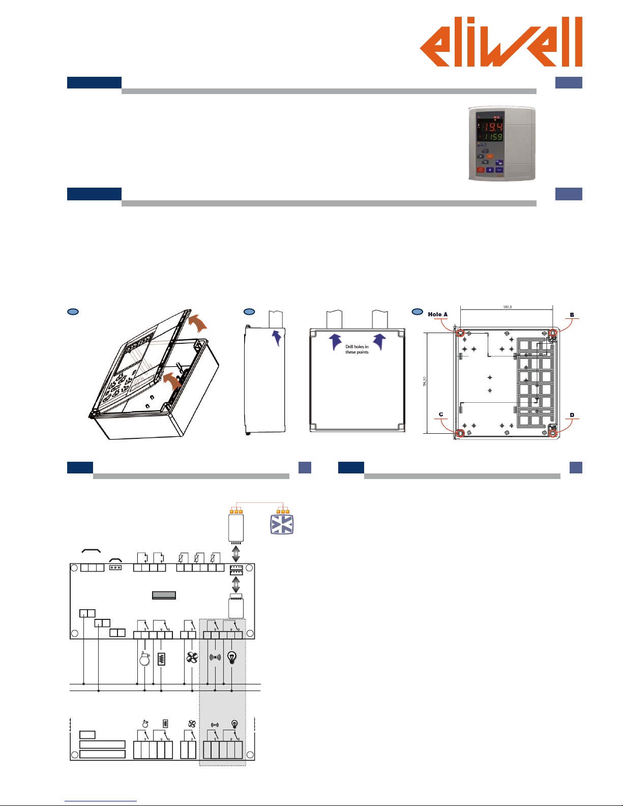
MECHANICAL ASSEMBLY
a) Remove the coverplate on the right side of the door, pressing lightly on
the points indicated by the arrows in Figure 1 and open the door.
b) Drill holes in the backplate at the top or bottom to pass the wires through.
See the example in figure 2.
c) Screw the backplate to the wall using 4 screws (not supplied) to match the
holes illustrated in Figure 3.
d) Shut the door by securing it with the 2 screws provided.
Replace the screw caps removed earlier from the door (see point a).
e) The door lock (an optional accessory) can be installed in 3 different
positions on the door, the holes to be drilled are indicated on the back.
Each position on the door represents a different position where the
disconnector can be mounted.
N.B.: to make it easier to wall mount the backplate, remove the door by pressing lightly on the left side (the side that the door is attached by). You will
also have to separate the base from the keypad by disconnecting the keypad
cable.
11
11
22
22
33
33
EWRC 300-500 LX
CCCCoooolllldddd FFFFaaaacccceeee FFFFaaaammmmiiiillllyy
yy • Quick Start
WIRING DIAGRAM
GND
485+
485-
RS-485
RS-485/TTL
Keyboard
Line
Neutral
Ground
EWRC 300-500 LX
19 20 21 22 23 24
Pb2
Pb1
Pb3
11 12 13 14
DI2
DI1
1 2 3
Line
Neutral
Ground
230V
230V
Removable
Connectors
Faston
LINE
NEUTRAL
Copy
Card
Bus
Adapter
RS 485
TTL
TTL
EWRC500LX only
Page 2
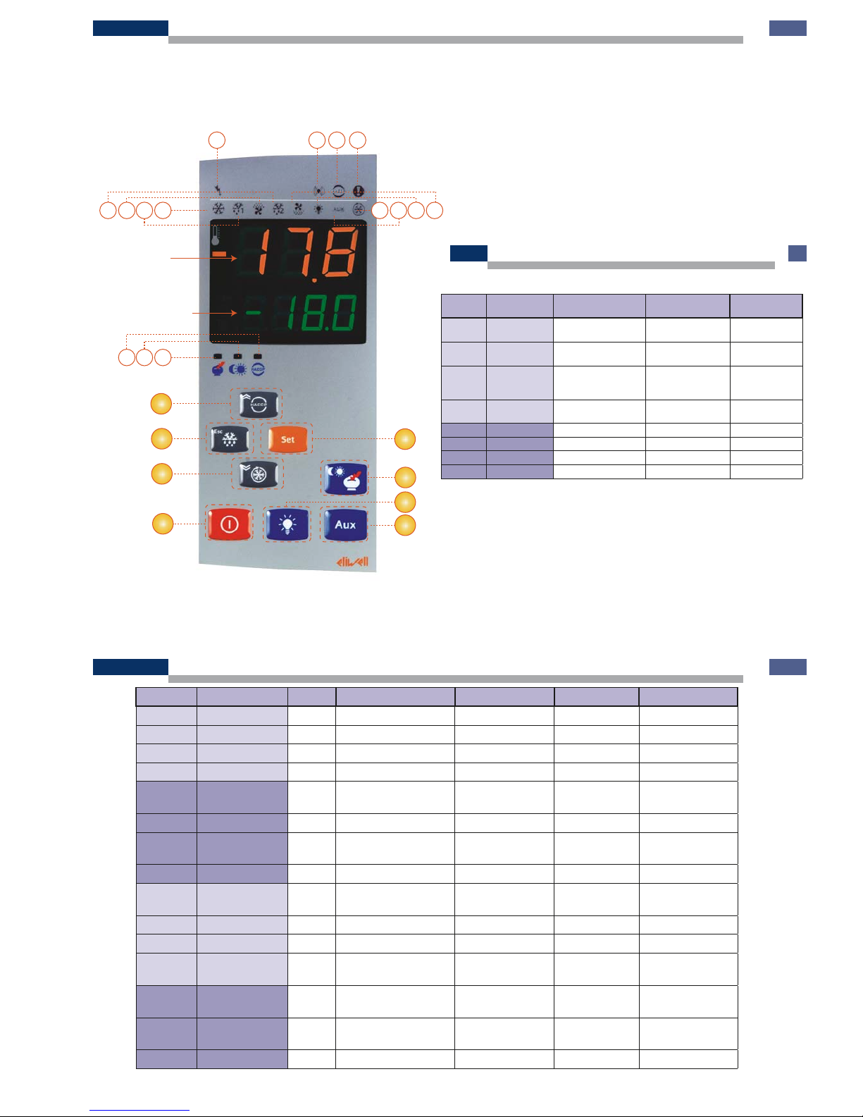
DISPLAY
Top Display 3 figures with + /- sign shows:
• Process Value
• parameters’ labels,
• alarms, functions
Bottom Display 4 figures shows:
• parameters’ value,
• function state / other
A
B
C
D
F
E
H
G
43
21
5678
131415
11 10 9
TOP DISPLAY
12
BOTTOM DISPLAY
Nr. LED color ON BLINK OFF Note
1 POWER red Power ON / Power OFF
2 ALARM red Alarm Silenced No Alarm
3 HACCP red HACCP Alarm Not Viewed No Alarm HACCP models
3 PANIC red Panic Alarm / No Alarm
5 COMPRESSOR yellow Compressor ON delay
Compressor
OFF
6 DEFROST 1 yellow defrost drip No defrost
7
EVAPORATOR
FANS
yellow Fans ON forced ventilation Fans OFF
8 DEFROST 2 yellow defrost drip No defrost
9
CONDENSER
FANS
yellow Fans ON / Fans OFF
10 LIGHT yellow Light ON / Light OFF
11 AUX yellow AUX ON / AUX OFF
12 DCC green
Deep Cooling Cycle
ON
/
Deep Cooling
Cycle OFF
13 ENERGY SAVING yellow Energy Saving ON /
Energy Saving
OFF
14
NIGHT AND
DAY
yellow Night and Day ON /
Night and Day
OFF
RTC models
15 HACCP yellow HACCP Menu / Other Menu HACCP models
Nr. KEY press and release
press approx
3 sec
Note
AUP
Scroll
Increase Values
HACCP menu H31
B ESC
Exit
Function Menu
manual defrost H32
C SET
Change SetPoint
Set Date / time
Enable Functions
Confi guration Menu
D DOWN
Scroll
Decrease Values
/ H33
E ENERGY SAVING Enable Energy Saving Night and Day Menu H37
F POWER Switch On / Off device drip H34
G LIGHT Switch On / Off Light forced ventilation H35
H AUX Aux / H36
LEDS
KEYS
Page 3

PARAMETERS
These are the most commonly used parameters. Their factory default values will suit normal electrical defrost applications. You can alter them to better
suit your particular application if you need to.
FOLDER LABEL DESCRIPTION RANGE DEFAULT M.U. Note
SEt Regulation SetPoint 0 °C/°F CutOut
CPr diF Differential 0 ... 30.0 2.0 °C/°F Related to SetPoint
CPr HSE Higher Set point adjustment limit LSE ... HdL 50.0 °C/°F
Minimum User can adjust
SetPoint
CPr LSE Lower Set point adjustment limit LdL ... HSE -50.0 °C/°F
Maximum User can adjust
SetPoint
CPr dOF Compressor Antishort cycle 0 ... 255 0 min Minutes
dEF dtY Defrost Mode 0 ... 2 0 num Electrical Defrost (1=HotGas)
dEF dit Interval between defrost 0 ... 255 6 h/min/sec Hours
dEF dCt defrost interval Counting mode 0 ... 3
3= RTC
models / 1
num
Time elapses since start of
last defrost
dEF dEt Maximum duration of Defrost 1 ... 255 30 h/min/sec Minutes
dEF dSt Defrost termination temperature -302.0 ... 1472.0 6.0 °C/°F
dEF dPO Execute a Defrost at Power On n/y n fl ag
FAn FSt Evaporator Fan Stop temperature -302.0 ... 1472.0 6.0 °C/°F
FAn Fdt Fan delay after defrost 0 ... 255 0 min Minutes
FAn dt Drip time 0 ... 255 0 min Minutes
FAn dFd Fan Stop during defrost n/y y fl ag
ALr HAL Maximum alarm threshold LAL ... 1472.0 50.0 °C/°F
ALr LAL Minimum alarm threshold -302.0 ... HAL -50.0 °C/°F
ALr dAO defrost Alarm Override 0 ... 999 60 min
Alarm delay after
defrost
ALr tAO Temperature Alarm Override 0 ... 255 0 min Temperature alarm delay
diS LOC Lock keyboard n/y n fl ag
diS PA1 Password 1 (USr) 0 ... 999 0 num
diS ndt number display type n/y y fl ag
diS CA1 Offset Probe 1 -30.0 ... 30.0 0.0 °C/°F Regulation Probe
diS CA2 Offset Probe 2 -30.0 ... 30.0 0.0 °C/°F Defrost termination Probe
diS ddL Lock display during defrost 0 ... 2 2 num Display shows “DEF”
CnF H00 Probe Type 0/1 1 fl ag
0=PTC; 1=NTC
depending on model
CnF H42 Defrost termination Probe presence n/y y fl ag Always present
HOW TO CHANGE THE SET POINT
• Press and release the SET button.
• The Top Display shows SET, the bottom display shows the value
• Use the UP & DOWN buttons to adjust the Set Point’s value
• Press ESC for display to return to normal
HOW TO ENTER THE USER LEVEL (USR) AND ALTER PARAMETER VALUES
• Press & Hold the SET button for 3 seconds until the display changes to
show USr
• Press & release SET to enter USr (User Level).
• The first parameter is displayed. Top display shows the parameter label,
Bottom display shows parameter value.
• Using the UP & DOWN buttons, go to the desired parameter
• Press & release SET, then using the UP & DOWN buttons, adjust the para-
meter’s value.
• Press ESC several times to return to normal display
ALL OTHER PARAMETERS ARE CONTAINED IN INSTALLER LEVEL (InS)
Entering Installer Level (InS):
You should only need to do this for more advanced applications. Here the
parameters are arranged in folders (Compressor / Defrost / Fans etc)
• Press & Hold the SET button for 3 seconds until the display changes to
show Usr
• Use the UP or DOWN button to display InS
• Press & release SET to enter InS (InStaller Level).
• The first parameter folder is displayed
• Keep pressing SET until you see the folder you want
• Press the UP or DOWN button, the first parameter is displayed. Top
display shows the parameter label, Bottom display shows parameter value.
• Using the UP & DOWN buttons, go to the desired parameter
• Press & release SET, then using the UP & DOWN buttons, adjust the parameter’s value.
• ress ESC several times to return to normal display
FOR MORE DETALED INFORMATION READ ON Technical Sheet p/n
9IS44058
cod. 9IS44112-1 - GB - rel. 07/08 © Eliwell Controls s.r.l. 2008 All rights reserved.
Eliwell Controls s.r.l.
Via dell’Industria, 15 • Zona Industriale Paludi • 32010 Pieve d’Alpago (BL) ITALY
Telephone +39 0437 986 111 • Facsimile +39 0437 989 066
Sales +39 0437 986 100 (Italy) • +39 0437 986 200 (other countries) • E-mail saleseliwell@invensyscontrols.com
Technical helpline +39 0437 986 300 • E-mail techsuppeliwell@invensyscontrols.com
www.eliwell.it
 Loading...