

Page 1
EWRC 300/500 NT
Controllers for static and ventilated cold rooms
English
QUICK START
Page 2
INTRODUCTION
The Coldface EWRC 300/500 NT series controls the temperature of a static or ventilated cold room.
The instrument controls positive and negative cold rooms and is capable of managing a double evaporator and condenser probes.
Coldface has 3 or 5 configurable relays depending on the model, 2(3) digital inputs configurable for
door switch or other devices. Models are available with clock with yearly calendar and HACCP event logging. Connection to TelevisSystem / Modbus is possible using the optional module plug-in RS485.
The container is used to install a magnetothermal switch or power contactor.
This summary document contains basic information about the standard models EWRC 300/500 NT.
For further information and different configurations, refer to the complete user manual cod. 9MA10258
downloadable free of charge from www.eliwell.com.
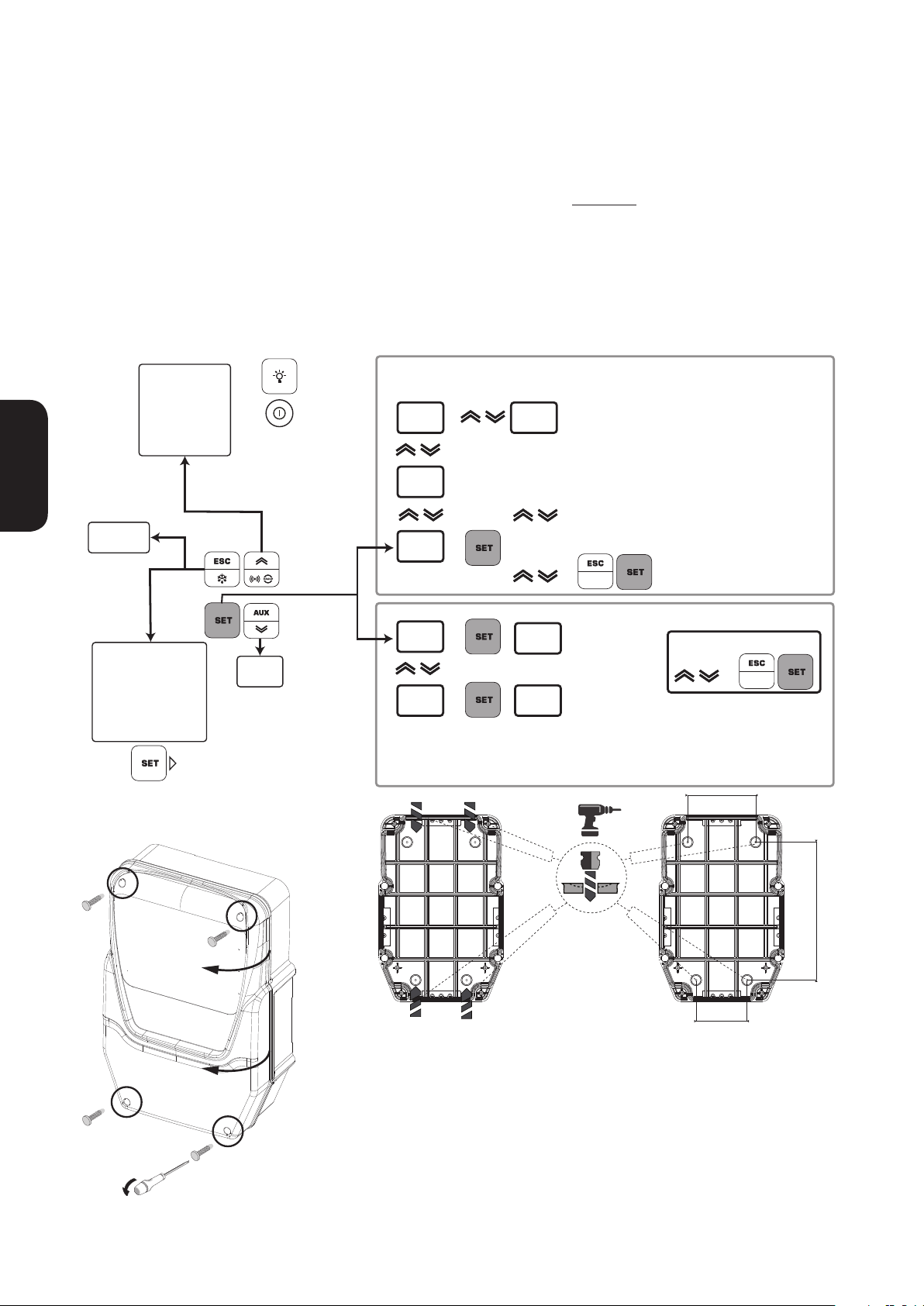
NAVIGATION DIAGRAM
Display alarms
if active
Display HACCP alarms
if function active
1 sec
English
Manual
defrost
rHC reset HACCP alarms
rSE active Set reduced
MECHANICAL INSTALLATION
3 sec
1 sec
Functions Menu
LOC keypad lock
rPA Pressure switch
rEd disable HACCP
function ON / OFF
Info
System
Turns light
on/o
Turns instrument
on/o
1 sec
3 sec
display probe
value
Pb1
-20.6
rtc
18.55
SET
-18.9
USr
inS
display probe
value
Pb2
-20.6
set time
and date
modify SetPoint
value
diF
2.0
CPr
- - -
conrm with
see manual
SetPoint & Probes
Parameters
modify value
conrm with
116
[UM] mm
A B
235
C
• Take out the 4 screws supplied and
then open the cover.
• Drill holes for the high and low voltage cable glands on the sides of the
backplate, as shown.
• Check that the cables are inside the
box.
• Use suitable cable glands and/
or conduit glands that guarantee an
airtight seal for all wiring.
See cutout at last page.
• Drill 4 holes (see A...D) in the wall and
fix the backplate using 4 screws (not
supplied) suited to the wall thickness.
• Insert plug covers TDI 20 (accessory
available on request)
• Close the door and screw on the 4
cover screws taking care that the hinges
are flush and do not interfere with the
closure of the cover.
EWRC 300/500 NT 2 - EN
D
87
Page 3
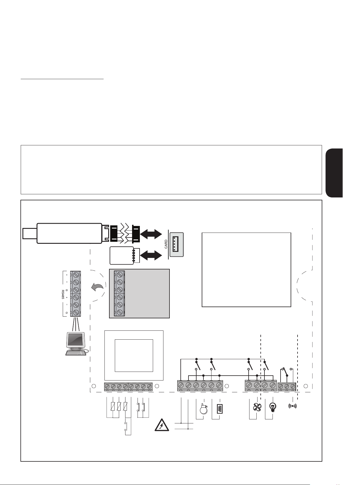
ELECTRICAL CONNECTIONS
Output relay (default settings)
• OUT1 relay 1 = Compressor
(or liquid line valve)
To switch between NTC/PTC probe types use parameter
H00. SWITCH OFF AND RESTART THE INSTRUMENT
after making the change.
• OUT2 relay 2 = Defrost
• OUT3 relay 3 = Evaporator fan
• OUT4 relay 4 = Light (EWRC 500 NT only)
OUT1-4 common-line max 18 A
• OUT5 relay 5 = Alarm/AUX (EWRC 500 NT only)
Probe inputs (default settings)
• Pb1 = NTC cold room probe
• Pb2 = NTC defrost end probe
• Pb3 = Not configured
Digital Inputs (default settings)
• DI1 = Door switch
• DI2 = not configured
• DI3 = not configured
Serial ports
• TTL for connection to UNICARD / Copy Card / MFK
• TTL for connection to TelevisSystem
• RS485 available ONLY with optional Plugin module
for connection to TelevisSystem / Modbus.
Important! Make sure the appliance is switched off before working on the electrical connections.
• Probe and digital inputs, OUT5 relay: screw-on terminals pitch 5.01: electric cables with max. cross-section
2.5 mm2 (only one wire per terminal for power connections).
• Power supply and relay OUT1..OUT4: screw-on terminals pitch 7.62: electric cables with max. cross-section
4mm2 (only one wire per terminal for power connections).
English
UNICARD
ELIWELL
ELIWELL
Yellow cable
COPY CARD
MFK
RS485
OPTIONAL
EWRC300/500 NT
DISPLAY
EWRC 500NT
OUT1 OUT2 OUT3 OUT4 OUT5
18 A max
only
COM
NONC
18 19 20 2117
1 2 3 4 5 6 7 8
GND GND GND+ +
+
+
PB1 PB2 DI2 DI1
PB3/DI3
230 Vac
L
N
H21
H22 H23 H24 H25
161514131211109
3 - EN EWRC 300/500 NT
Page 4

MODELS WITH COVER AND INSTALLED MINIATURE CIRCUIT BREAKER
EWRC 500 NT BREAKER | EWRC 500 NT 4-DIN
The versions with front door allow direct access to the switch miniature circuit breaker or to the top of the device
English
installed on the DIN rail mounted inside.
To open the front door, use both hands as shown above. Apply a slight pressure with your thumbs on top to
release the side flaps. Simultaneously with the index finger gently pull the door toward you.
In versions provided with the miniature circuit breaker, the installer must connect it to the power supply of the
electronic board through the wiring harness included in the packaging.
The wiring diagram is shown in the figure below.
In versions with transparent front door, the omega DIN rail is always available and already installed.
You can mount up to a maximum of 4 DIN modules, including 2DIN miniature circuit breaker when present.
The DIN housing is easily expandable from 2 to 4 DIN exploiting the pre-drilling barriers as shown in the top right.
EWRC500 NT BREAKER
OUT1 OUT2 OUT3 OUT4 OUT5
COM
NONC
18A max
18 19 20 2117
1 2 3 4 5 6 7 8
GND GND GND+ + +
PB1
PB2 DI2 DI1
+
H21
PB3/DI3
L
N
230 Vac
H22 H23 H24 H25
EWRC 300/500 NT 4 - EN
161514131211109
Page 5
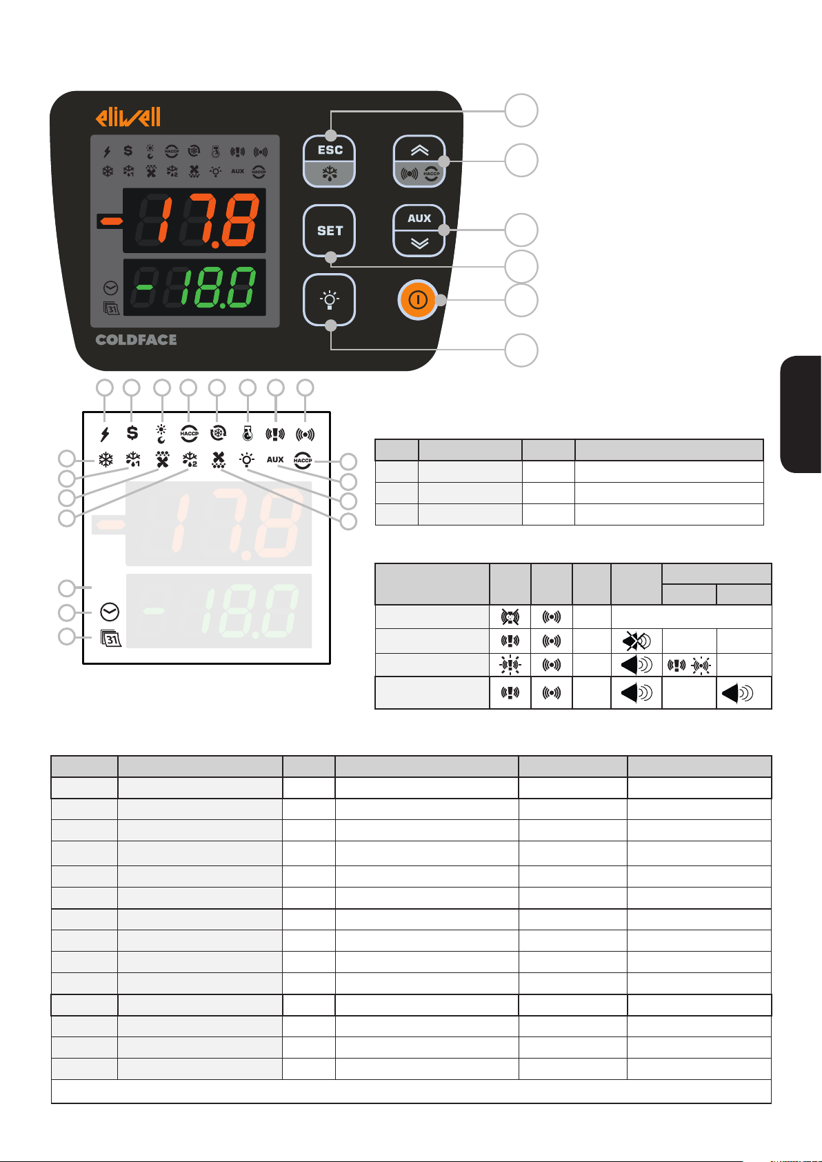
DISPLAY
%RH
1
2 3 4 5 6 7 8
LEDS
3-FIGURE UPPER DISPLAY
A
plus the - sign
Display:
• Operating value
B
• parameters label
• alarms, functions
if Upper display
C
it means that the value of the
blinking
Lower Display can be modified
D
E
F
4-FIGURE LOWER DISPLAY
Display:
• parameters value
• probe value
• function state
HACCP models
• time
English
N. LEDS Colour description
17 RH amber not used
18 TIME amber access in case of time display or editing
19 DATA amber access in case of date display or editing
10
11
12
9
13
14
15
16
ALARMS
17
%RH
18
19
No. LED Colour ON
1 POWER SUPPLY green Power supply ON / Power supply OFF
2 ENERGY SAVING amber Energy saving ON / Energy saving OFF
3 NIGHT & DAY amber Night & Day ON / Night & Day OFF
4 HACCP amber HACCP menu / /
5 DEEP COOLING (DCC) amber Drip cooling cycle ON / Drip cooling cycle OFF
6 PUMP DOWN amber Compressor Pump Down ON / Compressor Pump Down OFF
9 COMPRESSOR amber Compressor ON delay Compressor OFF
10 DEFROST 1 amber defrost coil drainage No defrost
11 EVAPORATOR FANS amber Fans ON forced ventilation Fans OFF
12 DEFROST 2 amber defrost coil drainage No defrost
13 HACCP ALARM red HACCP alarm Not displayed No alarm
14 AUXILIARY (AUX) amber AUX ON / AUX OFF
15 LIGHT amber Light ON / Light OFF
16 CONDENSER FANS amber Fans ON / Fans OFF
Alarms LED 7 LED 8
ALARM Red SEE "ALARMS TABLE" page 11”
PANIC Red --- ---
LEAK DETECTOR
PANIC +
LEAK DETECTOR
(1) = As long as the Panic alarm persists it will not be possible to mute the buzzer from the keypad.
Colour
BLINKING
ON: function/alarm ON; OFF: function/alarm OFF
Buzzer
Red
Red ---
LED Buzzer
...
OFF
Off
---
(1)
5 - EN EWRC 300/500 NT
Page 6

KEYS
No. KEY press and release
ESC key
A
Defrost
p UP
B
Alarms
• Functions Menu
• Alarms Menu (always visible)
press and hold for about
3seconds
• Manual defrost
• Return to Main Menu
/
• Display SetPoint / probe values /
time (Models with clock)
C SET
• Conrm values
• Access Parameters Menu
• Access value edit mode
(upper display blinking)
q DOWN
D
AUX
E ON/OFF /
system INFO
See Technical Support
Activate auxiliary function
Switch On/O
device
F LIGHT / Switch light on/o /
English
USER INTERFACE
NAVIGATION MENU Notes
• Output
• Scroll
• Increase values
• Conrm values
• Move right
HACCP alarms
only on foreseen models
and if present
display time
Models with clock only
• Scroll
• Decrease values
/
How to modify the SetPoint
• Press and release the SET key. The upper display will show SEt, the lower display will indicate the current SetPoint value
• Press and release the SET key once more. The upper display will show SEt blinking
• Use the UP & DOWN keys to adjust the Setpoint value
• Press the ESC key several times (or keep it pressed) to return to the normal display
How to read the probe value
• Press and release the SET key. The upper display will show SEt, the lower display will indicate the current SetPoint value
• Press and release the DOWN key. If the RTC clock is present, the time will be shown in the lower display
• Press and release the DOWN key once more. The upper display will show Pb1, the lower display will
indicate the value read by the room probe
• Press and release the DOWN key once more to read the value of probe Pb2 and Pb3 if configured
• Press the ESC key to return to the normal display.
How to modify the User Parameters
The user parameters are the most useful parameters and are described in this document, in the
section Parameters Table.
1) Press and hold the SET key for 3 seconds until the display shows PAr / USr
2) Press and release the SET key once more. The upper display will show the first parameter, the lower
display will indicate the current parameter value
3) Using the UP & DOWN keys, find the parameter that you wish to modify
4) Press and release the SET key once more. The upper display will show the name of the blinking parameter
5) Use the UP & DOWN keys to adjust the parameter value.
6) Press and release SET to save the parameter value
7) Return to step 3) or press ESC several times to return to the normal display
EWRC 300/500 NT 6 - EN
Page 7

USER PARAMETERS TABLE
This section describes the most commonly used parameters which are always visible (the access password PA1 is not enabled by default).
For a description of all other parameters, see the user manual.
NOTE: the user parameters ARE NOT divided into sub-folders and are always visible. The same parameters are also visible in the respective
folders ‘Compressor’, ‘Fans’, etc. (indicated also here to make the groupings clearer) in the password-protected Installer parameters menu.
PARA. DESCRIPTION U.M. RANGE DEFAULT
SEt Temperature control SEtpoint °C/°F -58.0...302 0.0
COMPRESSOR (CPr)
Activation differential
diF
N.B.: diF cannot be equal to 0.
Maximum value that can be assigned to the setpoint.
HSE
NOTE: The two setpoints are interdependent: HSE cannot be less than LSE and vice versa.
Minimum value that can be assigned to the setpoint.
LSE
NOTE: The two setpoints are interdependent: LSE cannot be greater than HSE and vice
versa.
Temperature value to be added algebraically to the Setpoint if reduced set enabled (Economy
OSP
function). Enabling can be controlled by a key, function or specially configured digital input.
Cit Minimum activation time of compressor before possible deactivation. If Cit = 0 not active. min 0 ... 255 0
CAt Maximum activation time of compressor before possible deactivation. If CAt = 0 not active. min 0 ... 255 0
Controller switch-on time in the event of faulty probe.
Ont
- if Ont = 1 and OFt = 0, compressor stays on permanently (ON).
- if Ont > 0 and OFt > 0, compressor operates in Duty Cycle mode.
Controller switch-off time in the event of faulty probe.
OFt
- if OFt = 1 and Ont = 0, compressor will always stay off (OFF).
- if Ont > 0 and OFt > 0, compressor operates in Duty Cycle mode.
Switch-on delay. The parameter indicates that a protection is active on the general compressor relay
dOn
actuations. At least the indicated time must elapse between the request and the actual activation of
the compressor relay.
Delay time after power-off: the delay time indicated must elapse between deactivation of the
dOF
compressor relay and the next power-on.
Delay time between power-ons; the delay time indicated must elapse between two consecutive
dbi
compressor power-ons.
Delay in activating outputs after the instrument is switched on or after a power failure.
OdO
0 = Not active
dS2 DEFROST (dEF)
Defrost mode
0 = Electric defrost (defrost cycle OFF), or compressor not running during defrost.
NOTE: electrical defrost + air defrost, in the case of fans connected in parallel to the defrost output
dtY
dit
dCt
dOH
dEt
dSt
relay.
1 = Cycle inversion defrost (hot gas, or compressor on during defrost)
2 = “Free” mode defrost (independent of compressor).
Interval between 2 defrost cycles
Interval between the start of two consecutive defrost cycles.
0 = Function disabled (defrost NEVER performed).
Defrost interval count mode
0 = Compressor running time (DIGIFROST® method);
defrost active ONLY when the compressor is on.
NOTE: compressor running hours are counted separately from the evaporator probe (count active also
when evaporator probe missing or faulty).
1 = Appliance running hours; defrost count is always active when machine is on and starts at each
power-up.
2 = Compressor stopped Every time the compressor stops, a defrost cycle is performed according to
parameter dtY;
3 = With RTC. defrost at specific times set by parameters dE1...dE8, F1...F8.
Defrost cycle enabling delay from request
Delay preceding start of first defrost after call.
Defrost timeout
Determines the maximum defrost time on Evaporator 1.
Defrost end temperature
Defrost 1 end temperature (determined by evaporator probe 1).
°C/°F 0 ... 30.0 2.0
°C/°F LSE ... HdL 50.0
°C/°F LdL ... HSE -50.0
°C/°F
min 0 ... 255 10
min 0 ... 255 10
sec 0 ... 255 2
min 0 ... 255 0
min 0 ... 255 2
min 0 ... 255 0
num 0 ... 2 0
hours/mins/
secs
num 0 ... 3 1
min 0 ... 59 0
hours/mins/
secs
°C/°F
-30.0 ...
30.0
0 ... 255 6 hours
1 ... 255 30 min
-302.0 ...
1472.0
0.0
6.0
English
7 - EN EWRC 300/500 NT
Page 8

PARA. DESCRIPTION U.M. RANGE DEFAULT
Defrost enabling request from power-on
Determines whether or not the instrument must defrost at power-up
dPO
(provided that the temperature measured at the evaporator will allow defrost).
n (0) = no, does not start defrosting at power-on; y (1) = yes, starts defrost at power-on
FANS (FAn)
Fans lockout temperature; if the value read is greater than FSt, the fans will be stopped. The value can
FSt
positive or negative
FAd Fans activation differential. °C/°F 0.1 ... 25.0 0.1
Fdt Fans activation delay after a defrost cycle. min 0 ... 250 0
dt dripping time. min 0 ... 250 0
Operating mode of evaporator fans during defrost.
dFd
n (0) = no (it depends on FCO parameter); y (1) = yes (fans excluded).
FCO Evaporator fans operating mode. The status of the fans will be:
A compressor ON fans thermoregulated, A compressor OFF depends on FCO
FCO=0, fans OFF
FCO=1-2, fans thermoregulated
FCO=3-4, fans in duty cycle
Dutycycle: controlled by way of parameters “FOn” and “FOF”.
ALARMS (ALr)
AFd Alarms cut-in differential. °C/°F 0.1 ... 25.0 1.0
Probe 1 maximum alarm. Temperature value (intended either as distance from setpoint or as an
HAL
English
absolute value based on Att) above which the probe will trigger activation of the alarm signal.
Probe 1 minimum alarm Temperature value (intended as distance from setpoint or as an absolute
LAL
value based on Att) beneath which the probe will trigger activation of the alarm signal.
Alarm override time after device is switched on following a power failure.
PAO
This parameter refers to high/low temperature alarms LAL and HAL only
dAO Temperature alarm override time after defrost. min 0 ... 250 60
Delay preceding indication of temperature alarm.
tAO
This parameter refers to high/low temperature alarms LAL and HAL only
DISPLAY parameters (diS)
LOCk. Setpoint edit lock. The parameter programming menu can still be accessed, and the settings
changed, which means also that the status of this parameter can be changed so as to unlock the
LOC
keypad.
n (0) = No
y (1) = yes.
PAssword 1. When enabled (PA1 ≠ 0) it is the access key for the
PA1
level 1 parameters (User).
Display values with decimal point.
ndt
n (0) = No (integers only)
y (1) = Yes (display with decimal point).
Calibration of probe Pb1.
CA1
Positive or negative temperature value added to the value read by Pb1. This sum is used for both
temperature display and temperature regulation purposes.
Calibration of probe Pb2.
CA2
Positive or negative temperature value added to the value read by Pb2. This sum is used for both
temperature display and temperature regulation purposes.
Display mode during defrost.
0 = Displays the temperature read by probe
1 = Locks the reading at the temperature value registering via the probe when the defrost cycle starts
ddL
H00
and until the next time the SEt is reached.
2 = Displays the label dEF during defrosting and until the next time the SEt is reached (or until Ldd
has elapsed).
CONFIGURATION (CnF)
If one or more parameters present in the folder are changed, the controller MUST be switched off and
switched on again.
Selection of type of probe used (Pb1 ... Pb3).
(0) = PTC
(1) = NTC
flag n/y n
°C/°F -58.0...302 0.0
flag n/y y
num 0 ... 4 1
°C/°F LA1...302 5.0
°C/°F -58.0...HA1 -5.0
hours 0 ... 10 3
min 0 ... 250 0
flag n/y n
num 0 ... 250 0
flag n/y y
°C/°F -30.0...30.0 0.0
°C/°F -30.0...30.0 0.0
num 0/1/2 1
num
0/1
(PTC/NTC)
1 (NTC)
EWRC 300/500 NT 8 - EN
Page 9

PARA. DESCRIPTION U.M. RANGE DEFAULT
Configuration of digital output 3 (OUT 3).
0 = disabled
1 = compressor
2 = defrost 1
H23
3 = Evaporator fans
4 = alarm
5 = AUX
6 = Stand-by
Evaporator probe (Pb2) present
H42
n (0) = not present
y (1) = present
rEL Firmware version release (e.g. 1,2,...). Read only. See Technical Support. / / /
tAb Map code. Read only. See Technical Support. / / /
COPY CARD parameters (FPr)
UL Upload. Transfer of programming parameters from instrument to Copy Card / / /
dL Download. Transfer of programming parameters from Copy Card to instrument / / /
Formatting. To erase data on Copy Card.
Fr
IMPORTANT: If parameter “Fr” is used, the data entered will be permanently lost. This
operation cannot be reversed.
7 = light
8 = Buzzer output
9 = defrost 2
10 = compressor 2
11 = frame heater
12 = Condenser fans
13 = Compressor Pump Down
num 0 ... 13 3
num n/y y
/ / /
THE INSTRUMENT IS USED TO EDIT OTHER PARAMETERS PRESENT IN THE
INSTALLER LEVEL (inS)
English
How to edit the installer level parameters
Procedure applies only to more advanced applications. In this case the parameters are arranged in folders (Compressor / Defrost / Fans etc)
1) Press and hold the SET key for 3 seconds until the display shows PAr / USr
2) Use UP & DOWN to select the parameter section inS
3) Press and release the SET key once more. The display will show the first folder
4) Press and release the SET key once more. The upper display will show the first parameter in the folder,
the lower display will indicate the current parameter value
5) Using the UP & DOWN keys, find the parameter that you wish to modify
The procedure proceeds in a similar manner to that described for the User parameters (points 4-7)
OPERATION IN DEFAULT CONFIGURATION
The instrument is configured for negative cold. For positive cold, disable the evaporator probe Pb2 (set
H42=n) and set relay OUT3 (parameter H23=6) to prevent continuous ventilation.
COMPRESSOR
The compressor is active if the cold room temperature detected by Pb1 exceeds the value of SEt + differential diF. The compressor stops if the cold room temperature detected by Pb1 falls below the SEt value.
The instrument includes compressor on/off protection*
DEFROST
Defrost is by means of electric heaters (parameter dty = 0) and the time counter is always active with the
instrument switched on (dCt=1).
Manual defrost
Manual defrost is activated by pressing and holding the ESC key (A).
If conditions for defrosting are not present, (e.g. the evaporator probe temperature is higher than the
defrost end temperature) or the parameter OdO≠0, the display will blink three times to indicate that the
operation will not be performed.
Default Defrost settings
dit = 6 hours. interval between 2 defrost cycles
dSt = 6.0 °C. defrosting end temperature set by Pb2.
The Defrost cycle may terminate due to timeout based on the parameter dEt (default 30 min).
EVAPORATOR FANS
Relay OUT3 is configured as fans relay and is activated in the required cases, according to delays and
parameter settings*
9 - EN EWRC 300/500 NT
Page 10

Default fan settings
dt = 0 min. dripping time
dFd = Y. Fans off during defrosting.
LIGHT (EWRC 500 NT)
The light is activated by pressing and holding the LIGHT key (F).
Since digital input D.I. 1 is configured as door switch, relay OUT4 (light) is activated when the door is
opened. The light also switches on with the instrument in stand-by*.
ALARM RELAY (EWRC 500 NT)
Relay OUT5 is configured as alarm relay and is activated in the case of alarms, according to delays and
parameter settings. *FOR MORE INFORMATION READ the manual, code 9MA10258
SUPERVISION
EWRC 300/500 NT can be connected to:
• TelevisSystem or external system remote control system via Modbus protocol
• DeviceManager fast parameter setting software
The connection can be made by direct RS-485 connection using the optional RS485/TTL plug-in module
(not included). See Electrical Connections.
*FOR MORE INFORMATION READ the manual, code 9MA10258
English
TECHNICAL SUPPORT
Please have the following information available when contacting Eliwell Technical Support:
• IdF firmware version (e.g. 554)
• rEL firmware version release (e.g. 1,2,...)
• tAb map code
• rC instrument model (e.g. 300 or 500)
To obtain this information:
• Press and release the DOWN / INFO key
• Press and release the DOWN key once more to display other information about the instrument.
• Press the ESC key to return to the normal display.
ALARMS AND TROUBLESHOOTING
How to display the alarms
1) Press and release the UP key. The upper display will always show the label ALr. The lower display will
show:
• nOnE if no alarms active
• SYS to indicate system alarms - see Alarms Table
• HACP to indicate HACCP alarms - see HACCP alarms
2) Using the UP & DOWN keys, find the type of alarm that you want to check
System alarms
The upper display will show the label ALr, the lower display will indicate the alarm code - see Alarms
Table
• Using the UP & DOWN key, scroll the other alarms
• Press the ESC key to return to the previous alarm code, press the ESC key several times (or keep it
pressed) to return to the normal display
HACCP ALARMS • AVAILABLE ONLY FOR HACCP MODELS
The instrument logs high and low temperature alarms for the cold room probe, as well as any power
failures. The alarm types and the duration and start time of the alarm itself will be displayed in the alarms
folder ALr. It is possible to disable the recording of alarms and/or resetting of HACCP alarms. See Functions Menu.
FOR MORE INFORMATION READ the manual, code 9MA10258
EWRC 300/500 NT 10 - EN
Page 11

ALARMS TABLE
This section lists alarms associated with the default conguration of the instrument.
For a description of alarms relating to custom congurations, refer to the user manual or contact Eliwell Technical Support.
Label Cause Eects Problem solving
Pb1 room probe faulty
• Measured values are outside operating
E1*
range
• Probe faulty/short-circuited/open
Pb2 defrost probe faulty
• Measured values are outside operating
E2*
range
• Probe faulty/short-circuited/open
Pb1 LOW temperature alarm
LA1
• Value read by Pb1 < LAL after time of
tAO.
Pb1 HIGH temperature alarm
HA1
• value read by probe Pb1 > HAL after
time of “tAO”.
End of defrost cycle due to time-out
Ad2
rather than due to defrost end temperature being read by the defrost probe
• Activation of digital input (set as door
switch) See para. H11/H12
OPd
• Depends on delay set by parameter tdO
• Label E1 displayed
• Disabling of maximum and minimum
alarm regulator
• Compressor operation based on parame-
• Check probe type NTC/PTC (see H00)
• Check probe wiring.
• Replace probe
ters “Ont” and “OFt” if set for duty cycle.
• Label E2 displayed
• The Defrost cycle will end due to timeout (Parameter “dEt”)
• Recording of label LA1 in folder ALr
• No eect on regulation.
• Recording of label HA1 in folder ALr
• No eect on regulation.
• Check probe type NTC/PTC (see H00)
• Check probe wiring.
• Replace probe
• Wait for the temperature value read by Pb1
to come back above LAL+AFd
• Wait until temperature value read by Pb1
returns below HAL-AFd.
• Recording of label Ad2 in folder ALr • Wait for the next defrost cycle for automatic
return
• Recording of label OPd in folder ALr
• Regulator locked (see para. dOA/PEA)
• Close door
• Depends on delay set by parameter OAO
English
E10**
**Models with clock only
Clock alarm clock faulty or battery low
Functions associated with clock not
present
Contact Eliwell Technical Support
ALL ALARMS
• Alarm icon permanently alight
• Buzzer (if present) and alarm relay (OUT5) activated, except Ad2
• Press any key to silence the alarm. The LED changes from a steady light to a blinking light. NOTE: the buzzer is deactivated while the alarm
relay remains active
*E1 - E2: If simultaneous they will be shown alternately on the display at a frequency of 2 seconds
WARNINGS
Important! Make sure the appliance is switched off before working on the electrical connections.
• Probe and digital inputs, OUT5 relay: screw-on terminals pitch 5.01: electric cables with max.
cross-section 2.5 mm2 (only one wire per terminal for power connections).
• Power supply and relay OUT1..OUT4: screw-on terminals pitch 7.62: electric cables with max.
cross-section of 4 mm2 (only one wire per terminal for power connections).
For the capacity of the terminals, see the label on the instrument. Outputs on OUT1-4 relay max. capacity
18A.
Do not exceed the maximum permitted current; for higher loads, use a contactor with sufficient power
capacity. Make sure that power supply is of the correct voltage for the instrument.
Probes have no connection polarity and can be extended using a normal two-core cable (note that
extension of the probe leads influences the instrument’s electromagnetic compatibility - EMC and
measurement class: take great care with the wiring). Probe cables, power supply cables and the TTL
serial cables should be routed separately from power cables.
11 - EN EWRC 300/500 NT
Page 12

TECHNICAL SPECIFICATIONS (EN 60730-2-9)
DESCRIPTION
Front panel
IP65
Classification
electronic automatic control device (not safety) device for stand-alone installation
wall mounted (distance between holes A-B 116 mm; holes C-D 87 mm holes A-C 235 mm
Hinges are available for mounting on special compartments for opening the cover both right
Screw on the respective anchoring screws taking care that the hinges are fitted well and lie flush
so that they do not interfere with the compression of the seal
Type of action
1.B
Pollution class
2
Material class
IIIa
Over voltage category
II
Nominal pulse voltage
2500 V
Operating temperature
-5 ... 50 °C
Power supply
230 Vac ± 10 % 50/60 Hz
Power consumption
11 VA max
EWRC 500 BREAKER version only
230 Vac Icn 4500 A, Bipolar (2P), for wires up to 10 mm
EWRC 500 BREAKER version only
In = 16 A
EWRC 500 BREAKER version only
4 KV
Digital outputs (relay)
refer to the label on the device
Fire resistance category
D
Software class
A
Connection
device on external flexible cable, Y type connection
Ball test temperature
100 °C
See Mechanical Installation paragraph
Installation
Miniature Circuit Breaker
English
Rated breaker current
Rated impulse voltage
and left.
2
EWRC 300/500 NT 12 - EN
Page 13

FURTHER INFORMATION
DESCRIPTION
Container
PC+ABS
Dimensions
front panel 213x318 mm, depth 102 mm
Dimensions
EWRC500 NT BREAKER version
screw-on terminals (see wiring diagram)
IMPORTANT: do not exceed ampere limits
Storage temperature
-20 ... 85 °C
Operating humidity
Storage humidity
–50 … 110 (NTC) / –55 … 150 °C (PTC) no decimal point, on 2 displays:
(upper display) 3 digit + sign/ (lower display) 4 digit
Analogue Inputs
3(2) NTC inputs PTC configurable by parameter H00
Digital Inputs
2(3) digital inputs no voltage configurable from parameter H11/H12/H13
EWRC 300 NT version
EWRC 500 NT version
common-line max 18 A
Buzzer
only on models where this is provided
• 1 TTL port for connection to Unicard / Copy Card / MFK
(use with optional plug-in module)
Accuracy
better than 0.5 % of end of scale +1 digit
Resolution
1 or 0.1 °C
RTC battery life
In a power failure, the clock battery will last 4 days.
front panel 221x318 mm, depth 107 mm
Connections
Display range
Relay outputs
Serial ports
with internal housing for magnetothermal switch,
remote control switch, contactor, etc. on DIN rail
10…90 % RH non-condensing
• OUT1 output SPST 2 HP 12(12) A 250 Vac
• OUT2 output SPST 1 HP 8(8) A 250 Vac
• OUT3 output SPST 1/2 HP 8(4) A 250 Vac
common-line max 18 A
• 1 TTL port for connection to TelevisSystem
• 1 RS-485 serial port for connection to TelevisSystem / Modbus
English
• OUT1 output SPST 2 HP 12(12) A 250 Vac
• OUT2 output SPST 1 HP 8(8) A 250 Vac
• OUT3 output SPST 1/2 HP 8(4) A 250 Vac
• OUT4 output SPST 1 HP 8(8) A 250 Vac
• OUT5 output SPDT 1/2 HP 8(4) A 250 Vac
13 - EN EWRC 300/500 NT
Page 14

Food safety
The device complies with standard EN13485 as follows:
- Suitable for storage.
- Application: air.
- Climate range A.
- measurement class 1 in the -25 °C and 15 °C (exclusively using Eliwell probes)
CONDITIONS OF USE - Permitted use
For safety reasons, the device must be installed and used in accordance with the instructions provided. In particular,
parts carrying dangerous voltages must not be accessible under normal conditions.
The device must be adequately protected from water and dust with regard to the application, and must only be
accessible using tools (with the exception of the front panel).
The device is suitable for use as a stand-alone unit and has been tested for safety aspects in accordance with
harmonised European reference standards.
Prohibited use
Any use other than that expressly permitted is prohibited.
The relays provided are of a functional type and can be subject to failure: any protection devices required by
product standards, or suggested by common sense for obvious safety requirements, must be installed externally to
the controller.
RESPONSIBILITY AND RESIDUAL RISKS
Eliwell Controls srl declines any liability for damage due to:
English
• installation/uses other than those expressly specified and, in particular, failure to comply with the safety
requirements of established standards and/or instructions specified in this document;
• use on panels that do not provide adequate protection against electric shock,
water or dust, when mounted;
• Use on panels allowing access to dangerous parts without having to use tools.
• Tampering with and/or modification of the product.
• Installation/use on panels which are not compliant with current standards and regulations.
DISCLAIMER
This document is the exclusive property of Eliwell and cannot be reproduced or circulated unless expressly
authorised by Eliwell. All possible care has been taken to ensure the accuracy of this document; nevertheless,
Eliwell Controls srl cannot accept liability for any damage resulting from its use. The same applies to any person or
company involved in the creation and preparation of this document. Eliwell reserves the right to make aesthetic or
functional changes at any time without notice.
DISPOSAL
The equipment (or product) must be subjected to separate waste collection in compliance with
the local legislation on waste disposal.
EWRC 300/500 NT 14 - EN
Page 15

CUT OUT
45
25
UM [mm]
110
60
SCALE 1:1
Lower Side
when printed A5 format
6.5
29
Page 16

Eliwell Controls s.r.l.
Via dell’Industria, 15 • Z.I. Paludi
32010 Pieve d’Alpago (BL) ITALY
T +39 0437 986 111
www.eliwell.com
Technical Customer Support
T +39 0437 986 300
E techsuppeliwell@schneider-electric.com
Sales
T +39 0437 986 100 (Italy)
T+39 0437 986 200 (other countries)
E saleseliwell@schneider-electric.com
9IS54389 - EN - rel. 10/16
© Eliwell Controls s.r.l. 2014-2016 All rights reserved.
 Loading...