

Page 1
Electronic controllers for refrigeration units
Controles electrónicos para unidades de refrigeración
Contrôleurs électroniques pour unités réfrigérantes
Controladores eletrônicos para unidades de refrigeração
EWP ///
Installation manual includes:
English, Spanish, French, and Portuguese
Page 2

Page 3
3
Electronic controllers for refrigeration units
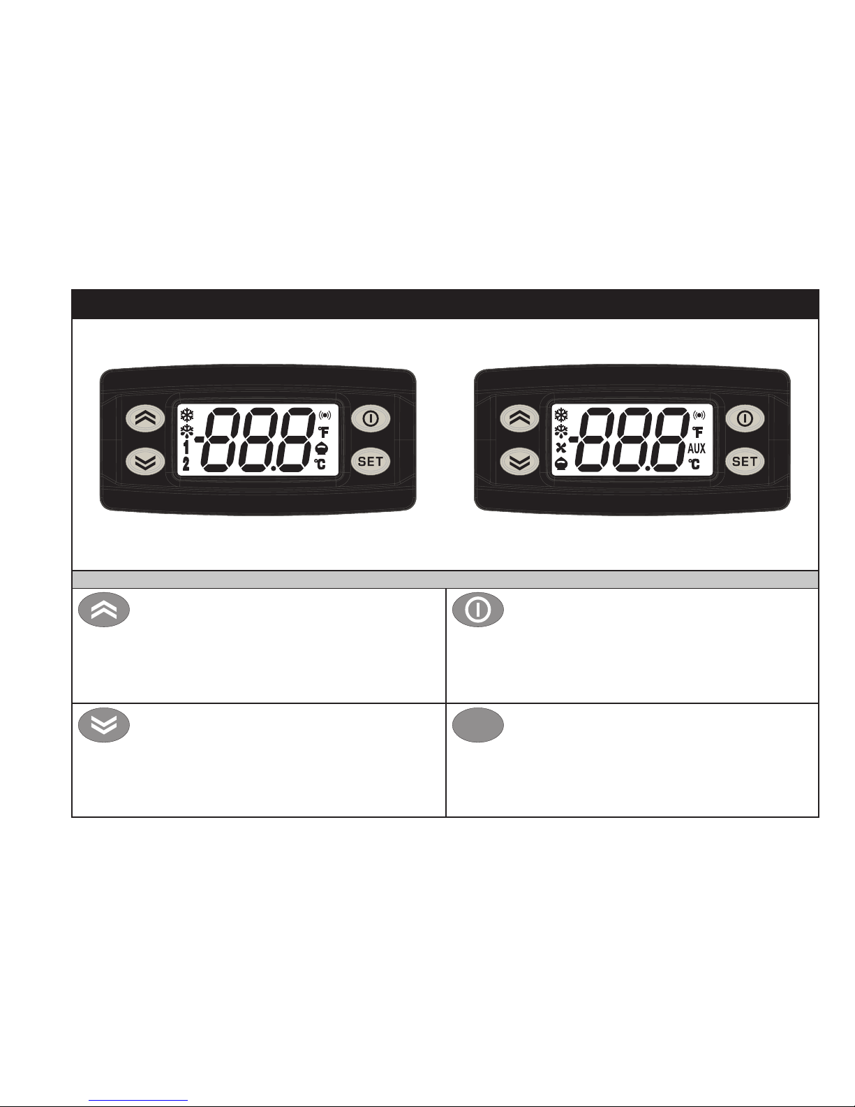
STAND-BY (ESC)
Press and release
Returns to the previous menu level
Confirm parameter value
Press for at least 5 secs
Activates the Stand-by function
(when outside the menus)
UP
Press and release
Scrolls through menu items
Increases values
Press for at least 5 secs
Activates the Manual Defrost function
DOWN
Press and release
Scrolls through menu items
Decreases values
Press for at least 5 secs
Configurable function by user (par.H32)
SET (ENTER)
Press and release
Displays alarms (if active)
Opens the Machine Status menu
Press for at least 5 secs
Opens the Programming menu
Confirms commands
set
KEYS
EW
PL
US
902/961
EW
PL
US
971/974
ENGLISH
Page 4

4
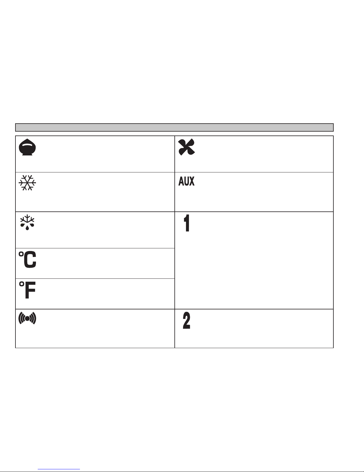
LEDs
Reduced SET / Economy
Flashing: reduced set active
Quick flashing: access to level 2 parameters
Off: otherwise
Compressor LED
Permanently on: compressor active
Flashing: delay, protection or
blocked start-up
Off: otherwise
Defrost LED
Permanently on: defrost active
Flashing: manual or D.I. activation
Off: otherwise
Fan LED
Permanently on: fans active
Off: otherwise
(only EWPlus 971 and EWPlus 974)
Alarm LED
Permanently on: alarm on
Flashing: alarm acknowledged
Off: otherwise
HEAT mode LED
Permanently on: compressor in HEAT mode
Off: otherwise
(only EWPlus 902 and EW Plus 961)
NOT USED
(only EWPlus 902 and EWPlus 961)
Aux LED
Permanently on: Aux active*
*depending on model
(only EWPlus 971 and EWPlus 974)
°C LED
Permanently on: °C setting (dro = 0)
Off: otherwise
°F LED
Permanently on: °F setting (dro = 1)
Off: otherwise
NOTE:
If the instrument is set in the COOL mode, in order to
use it in the HEAT mode it is necessary to re-program
the instrument by using the properly programmed
Copycard.
The same procedure should be followed to pass from
the HEAT mode to the COOL mode.
Page 5
5
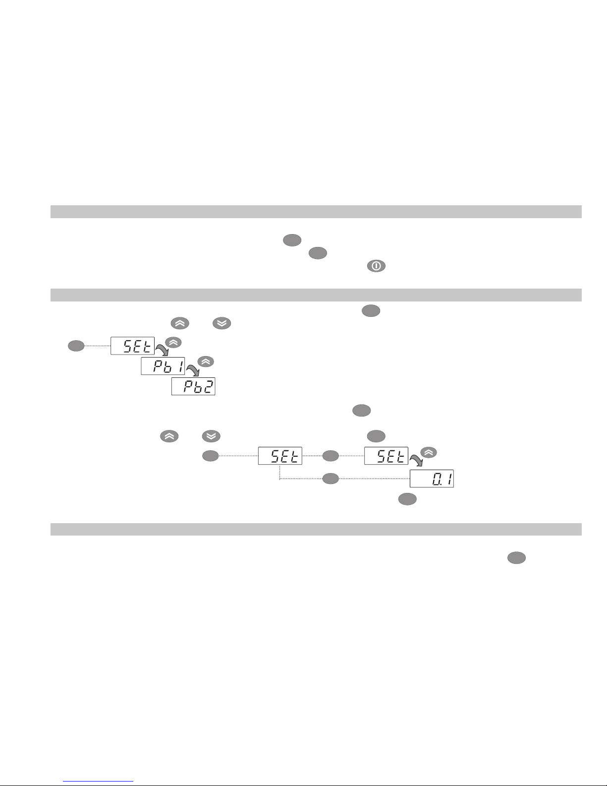
ACCESSING AND USING THE MENUS
Resources are organized into 2 menus which are accessed as explained below:
• ‘Machine Status’ menu: press and release the
set
key.
• ‘Programming’ menu: press for at least 5 secs the
set
key.
Either do not press any keys for 15 seconds (time-out) or press the key once, to confirm the last value
displayed and return to the previous screen.
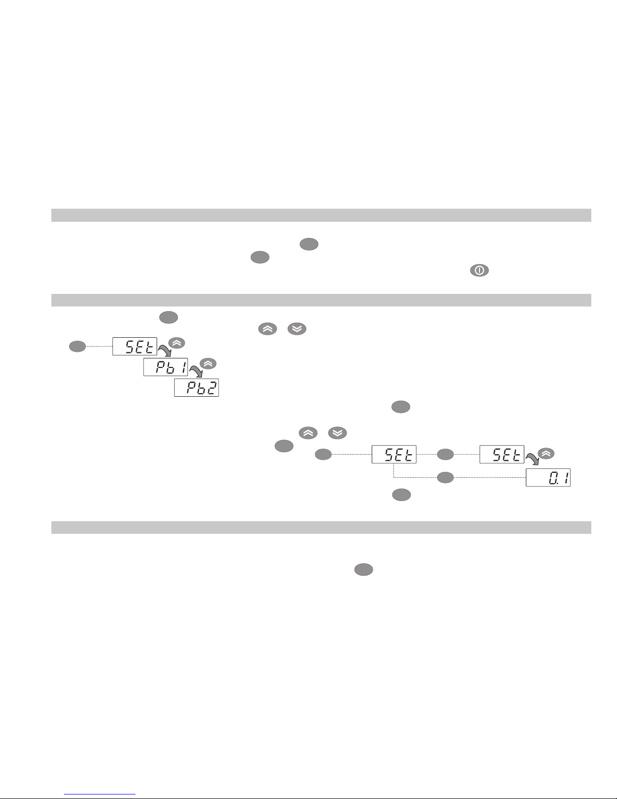
MACHINE STATUS MENU
Access the “Machine Status” menu by pressing and releasing the
set
key. If no alarms are active, the “SEt” label
appears. By pressing the
and keys you can scroll all folders in the “Machine Status” menu:
- AL: alarms folder (only visible if an alarm is active);
- SEt: Set point setting folder;
- Pb1: probe 1 folder;
- Pb2: probe 2 folder **;
(** models EWPlus 971 and EWPlus 974 only)
Setting the Set point: To display the Set point value press the
set
key when the ‘SEt’ label is displayed.
The Set point value appears on the display. To change the Set point value, press the
and keys within 15 seconds. Press
set
to confirm the modification.
set
set set
Displaying the probes: When the Pb1 or Pb2* label is displayed, press
set
and the associated probe value
will appear (* Pb2 is only present on models EWPlus 971 and EWPlus 974).
SET POINT EDIT LOCK
It is possible to disable the keypad on this device. The keypad can be locked by programming the ‘LOC’
parameter. With the keypad locked you can still access the ‘Machine Status’ menu by pressing
set
to display
the Set point, but you cannot edit them. To disable the keypad lock, repeat the locking procedure.
set
Page 6
6
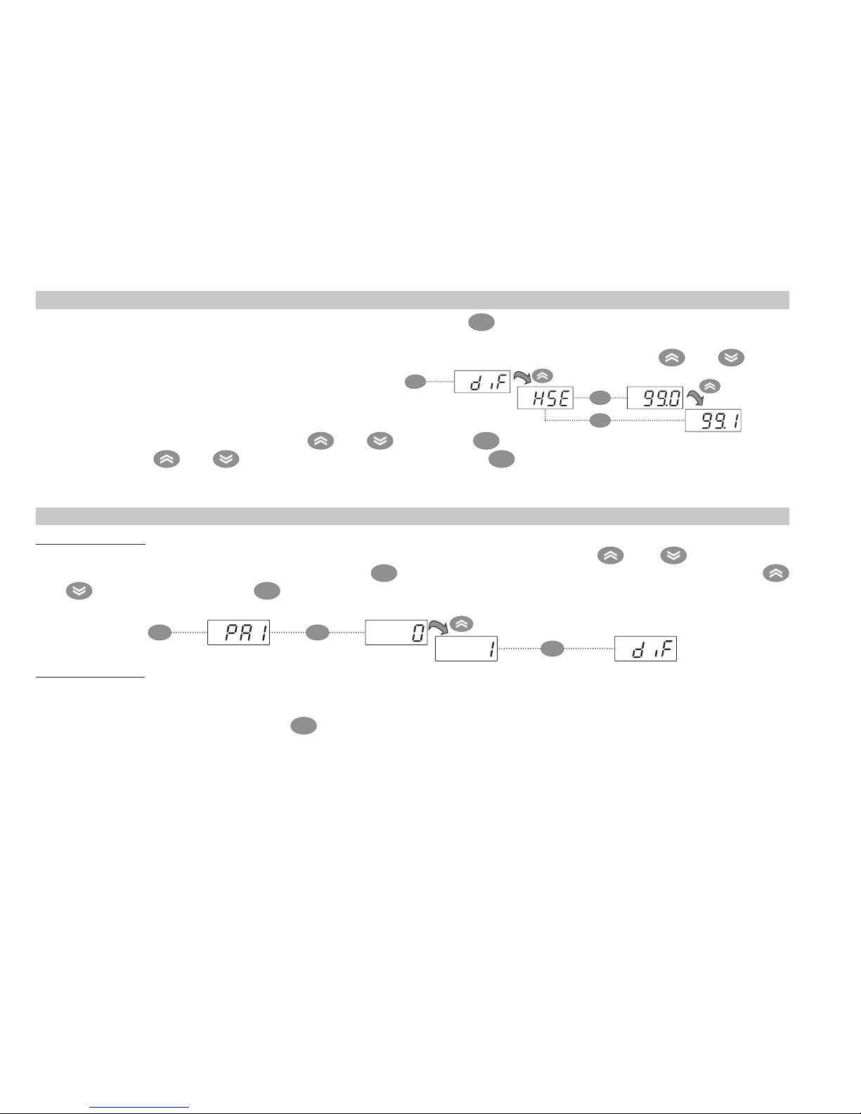
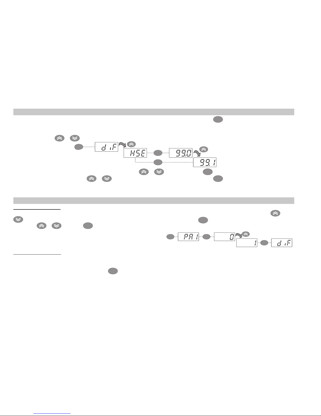
PROGRAMMING MENU
To access the ‘Programming’ menu press for at least 5 secs the
set
key. If specified, the ‘PA1’ for the level
1 parameters and the ‘PA2’ for the level 2 parameters access PASSWORD will be requested (see Par.
‘PASSWORD’) At the access, the display will show the first parameter (“diF”). By pressing the
and keys
you can scroll all parameters in the current level:
5 secs
Select the desired parameter using the and keys. Press
set
to see the current value of the selected
parameter. Press and to change the value and then press
set
to save it.
NOTE: It is strongly recommended that you switch the device off and on again each time the parameter
configuration is changed, in order to prevent malfunctioning of the configuration and/or ongoing timings.
PASSWORD
‘PA1’ Password: It allows access to the level 1 parameters. In the standard configuration the password is disabled
(value = 0). To enable it (value ≠ 0) enter the “Programming” menu by pressing the
and keys, scroll the
parameters until “PS1” label is displayed, press the
set
key to display the current value, change it by using the
and
keys and then press the
set
key to save it. If the password is already enabled, you will be required to enter
it to access the ‘Programming’ menu. To enter it:
set
setset
‘PA2’ Password: It allows access to the level 2 parameters. In the standard configuration the password is enabled
(valore ≠ 0). To change its value follow the steps like for ‘PA1’ and change the ‘PS2’ parameter value.
The visibility of the ‘PA2’ label will be:
1) If PA1 and PA2 ≠ 0: By pressing the
set
key for more than 5 seconds, “PA1” and “PA2” labels will be displayed
at the same level and it will be possible to access either the level 1 or the level 2 parameters.
2) Otherwise: The ‘PA2’ password is present between the level 1 parameters. If ‘PA2’ is enabled, you will be required
to enter it to access the level 2. To enter it follow the steps described for the ‘PA1’ password.
If the password is incorrect, the instruments display the PA1/PA2 label and you will have to repeat the entry
procedure.
set
set
set
Page 7
7
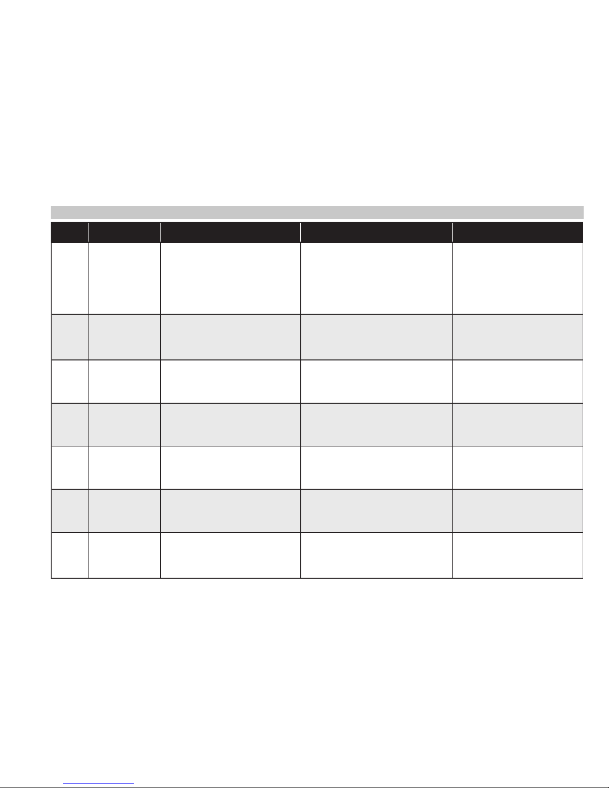
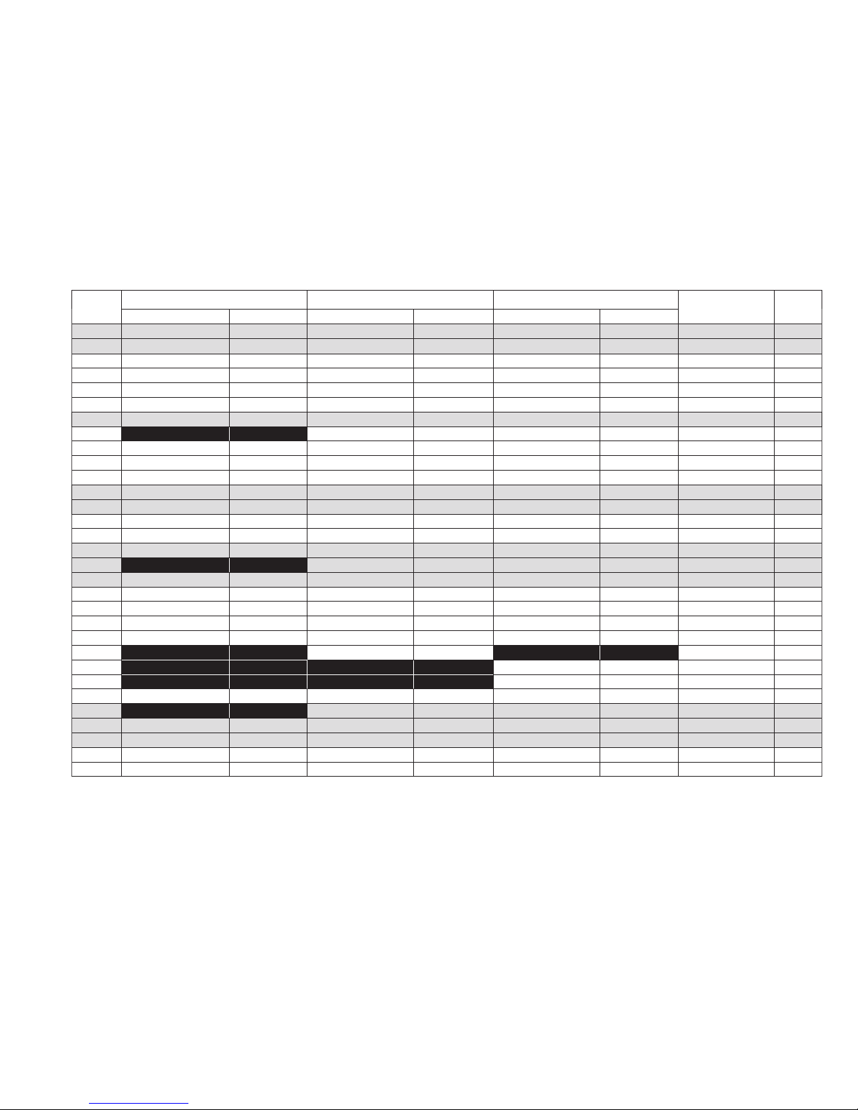
ALARMS
Label Fault Cause Effects Remedy
E1
Probe1 faulty
(cold room)
• Reading of out of range operating
values
• Probe faulty / short-circuited / open
• Display label E1
• Alarm icon permanently ON
• Min/max alarm regulator disabled
• Compressor operation according to
“Ont” and “OFt” parameters.
• Check probe type (NTC)
• Check the probe wiring
• Replace probe
E2
Probe2 faulty
(defrost)
• Reading of out of range operating
values
• Probe faulty / short-circuited / open
• Display label E2
• Alarm icon permanently ON
• The defrost cycle will end due to
Time-out (Parameter “dEt”)
• Check probe type (NTC)
• Check the probe wiring
• Replace probe
AH1
Probe1 HIGH
Temperature
alarm
Value read by Pb1 > HAL after time
of “tAO”.
(see “MAX/MIN TEMP. ALARMS “)
• Registration AH1 label in the AL folder
• No effect on regulation
• Wait until temperature value
read by probe1 returns below
HAL.
AL1
Probe1 LOW
Temperature
alarm
Value read by Pb1 < LAL after time
of “tAO”.
(see “MAX/MIN TEMP. ALARMS”)
• Registration AL1 label in the AL folder
• No effect on regulation
• Wait until temperature value
read by probe1 to come back
obove LAL
EA External alarm
• Digital input activated
(H11 = ±5)
• Registration EA label in the AL folder
• Alarm icon permanently ON
• Regulation blocked if EAL = y
• Check and remove the external
cause which generate alarm
on D.I.
OPd Door Open alarm
• Digital input activated
(H11 = ±4)
(for a longer time than tdO)
• Registration Opd label in the AL folder
• Alarm icon permanently ON
• Regulator blocked
• Close the door
• Delay function defined by OAO
Ad2
Defrosting
for time-out
• End of defrosting because of time
instead of because of reaching the
defrost end temperature detected
by the Pb2 probe.
• Registration Ad2 label in the AL folder
• Alarm icon permanently ON
• Wait until the next defrost for
automatic return
Page 8
8
MANUAL DEFROST CYCLE ACTIVATION
To manually activate the defrost cycle, hold down the key for 5 seconds.
If the defrost conditions are not satisfied:
- the parameter OdO ≠ 0 (EWPlus 902/961/971/974)
- the evaporator probe Pb2 temperature is higher than the defrost end temperature (EWPlus 971/974)
the display will flash 3 times, to indicate that the operation will not be carried out.
DIAGNOSTICS
Alarms are always indicated by the buzzer (if present) and the alarm icon .
To switch off the buzzer, press and release any key, the relative icon will continue to flash.
NOTES: If alarm exclusion times have been set (see ‘AL’ folder in the parameters table) the alarm will not be
signalled.
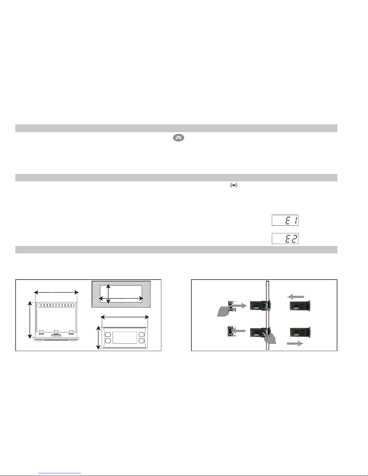
A probe 1 (Pb1) malfunction alarm will appear directly on the display with the
indication E1.
Models EWPlus 971/974: A probe 2 (Pb2) malfunction alarm will appear
directly on the display with the indication E2.
MECHANICAL ASSEMBLY
The instrument is designed for panel mounting. Make a hole of 2-13/16” x 1-1/8” (71x29mm), insert the instrument and fix it using the brackets provided. Do not mount the instrument in humid and/or dirty places; it is
suitable for use in ordinary polluted places. Ventilate the place in proximity to the instrument colling slits.
74 mm
32 mm
29 mm
71 mm
70 mm
59 mm
Page 9
9
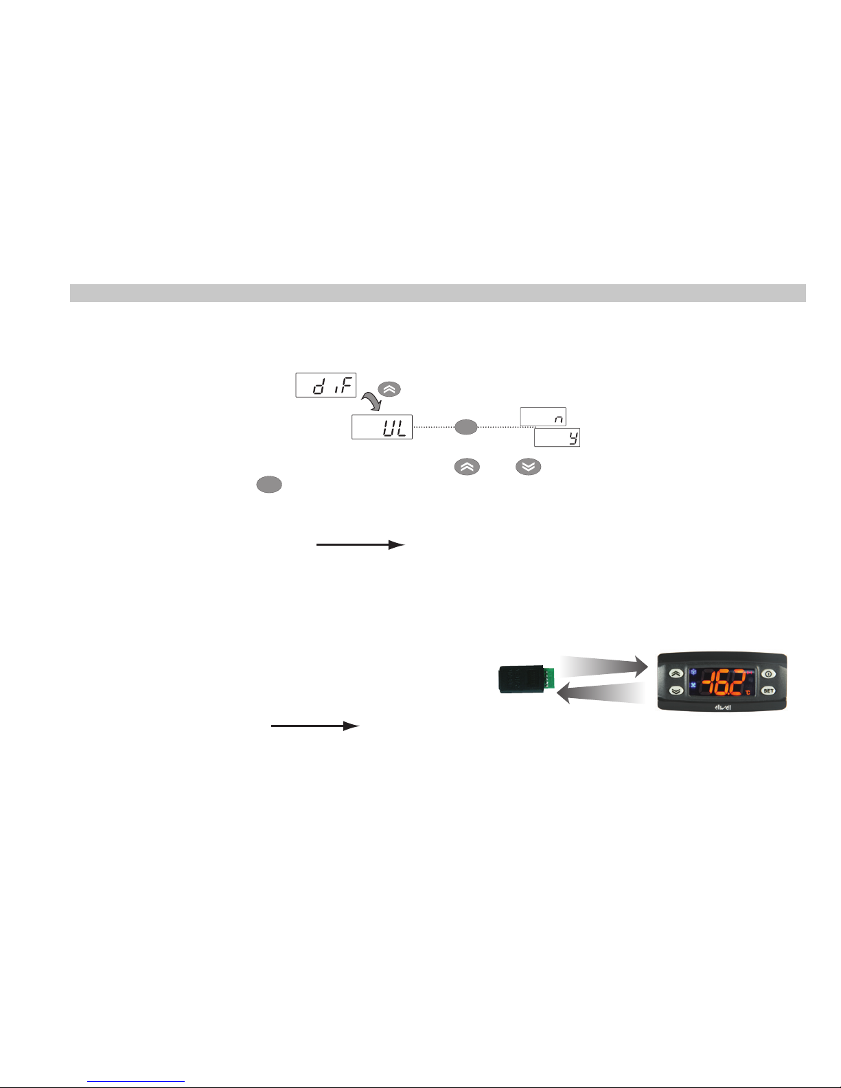
USING THE COPY CARD
The Copy Card is an accessory connected to the TTL serial port used for quick programming of the device
parameters (upload and download a parameter map to one or more devices of the same type). Upload (label
UL) and copy card formatting (label Fr) operations should be performed as explained below:
set
After the password ‘PA2’ has been putted in, press the and keys to scroll through to the required
function (e.g. UL). Press the
set
key to execute the upload. If the operation is successful, the display will show
‘y’, if not it will show ‘n’.
Upload (UL) This function uploads the programming parameters from the device.
UPLOAD: device
Copy Card
Format (Fr) This command is used to format the copy card, an operation which is necessary when using the
card for the first time. Important: when the copy card has been programmed, the parameter
‘Fr’ will delete all data that have been entered. This operation cannot be cancelled.
Download from reset:
Connect the copy card when the device is switched off. When
the device is switched on, the download from the copy card will
begin automatically. At the end of the lamp test, the display will
show ‘dLy’ if the operation was successful and ‘dLn’ if not.
DOWNLOAD: Copy Card
device
NOTES:
- After the parameters have been downloaded, the device uses the downloaded parameter map settings.
UPLOAD
DOWNLOAD
Page 10
10
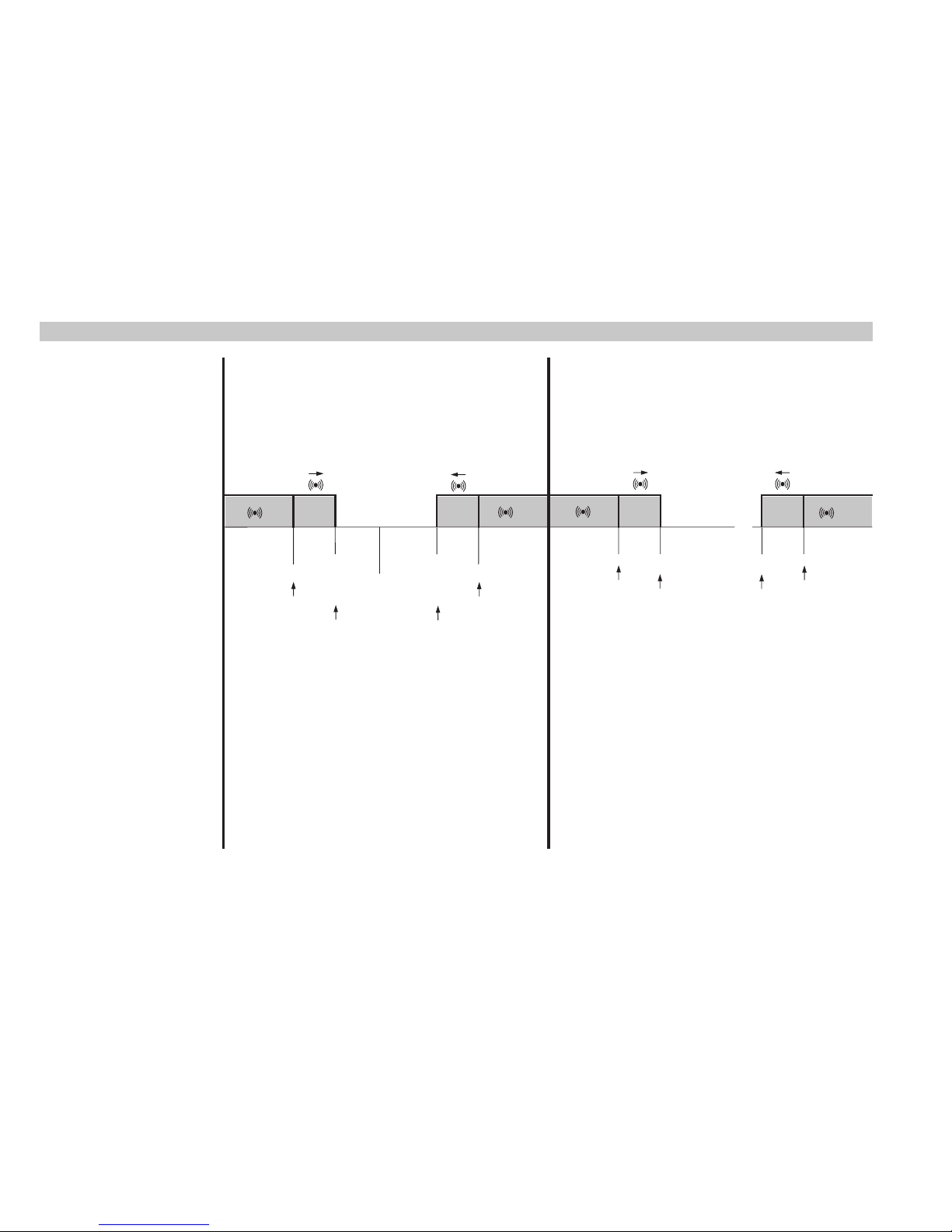
MAX/MIN TEMPERATURE ALARM
Relative Temperature
Value to Setpoint (Att=1)
Absolute Temperature
Value (Att=0)
Temp. ≤ Set + LAL *
Temp. ≥ Set + HAL **
Temp. ≥ Set + LAL + AFd or
≥ Set - ILALI + AFd (LAL < 0)
Temp. ≤ Set + HAL - AFd (HAL > 0)
Temp. ≤ LAL (LAL with sign)
Temp. ≥ HAL (HAL with sign)
Temp. ≥ LAL + AFd
Temp. ≤ HAL - AFd
Minimum temperature
alarm
Maximum temperature
alarm
Returning from
minimum temp. alarm
Returning from
maximum temp. alarm
* if LAL is negative, Set + LAL < Set
** if HAL is negative, Set + HAL < Set
Setpoint - LAL
AFd
Off
Setpoint + HAL
AFd
Setpoint - LAL + AFd
Setpoint + HAL - AFd
Setpoint
LAL
AFd
HAL
AFd
LAL + AFd
HAL - AFd
Page 11

11
CONDITIONS OF USE
Permitted use
For safety reasons the instrument must be installed and used according to the instruction provided and in
particular, under normal conditions, parts bearing dangerous voltage levels must not be accessible. The
device must be adequately protected from water and dust as per the application and must also only be
accessible via the use of tools (with the exception of the frontlet).
The device is ideally suited for use on household appliances and/or similar refrigeration equipment and has
been tested with regard to the aspects concerning European reference standards on safety.
Unpermitted use
Any other use other than that permitted is de facto prohibited. It should be noted that the relay contacts
provided are of a practical type and therefore subject to fault. Any protection devices required by product
standards or dictated by common sense due to obvious safety reasons should be applied externally.
TECHNICAL DATA
Classification: Control device (not safety) to integrate
Mounting: Panel mounting with 2-13/16” x 1-1/8” (71x29mm) drilling template
Control type: 1.B
Pollution rating: 2
Material class: IIIa
Overvoltage category class: II
Nominal impulsive voltage: 2500V
Temperature: Operating: –5 to +65°C (+23 to +149°F) - Storage: –30 to +85°C (–22 to +185°F)
Power Supply: 115Va or 230Va (
+
10% / -10%) 50/60 Hz
Consumption: 4VA max
Digital Output (relays): Please refer to the device label
Fire resistance class: D
Software class: A
NOTE: Check the power supply specified on the instrument label; for relay and power supply
capacities, contact Technical Service.
Page 12
12
Input Characteristics
Display Range: NTC: –50°C to +110°C (–58°C to +230°F)
(on display with 3 digit + sign)
Accuracy: Better than 0.5% of full-scale + 1 digit
Resolution: 0.1°C (0.1°F up to 199.9 ; 1°F beyond)
Buzzer: YES (it depends on the model)
Analogue Input: EWPlus 902/961: 1 NTC input - EWPlus 971/974: 2 NTC inputs
Digital Input: 1 voltage-free digital input
Output Characteristics
Digital Output:
Model Relay Type of load
Power Supply 115V
a Power Supply 230Va
EWPlus 902:
OUT1 - N.O.
Resistive 8A 8A
Motor 1/8 Hp 1/2 Hp
OUT1 - N.C. Resistive 6A 6A
EWPlus 961: Compressor Motor 16 FLA / 96 LRA 12 FLA / 72 LRA
EWPlus 971:
Compressor Motor 16 FLA / 96 LRA 12 FLA / 72 LRA
Defrost - N.O.
Resistive 8A 8A
Motor 1/8 Hp 1/2 Hp
Defrost - N.C. Resistive 6A 6A
EWPlus 974:
Compressor Motor 16 FLA / 96 LRA 12 FLA / 72 LRA
Defrost - N.O.
Resistive 8A 8A
Motor 1/8 Hp 1/2 Hp
Defrost - N.C. Resistive 6A 6A
Fan
Resistive 3A 3A
Motor 1.4 FLA / 7.5 LRA 1.4 FLA / 7.5 LRA
Mechanical Characteristics
Housing: PC UL94 V-0 resin plastic casing, polycarbonate glass
Dimensions: Front 2-15/16” x 1-1/4” (74x32mm), depth 2-15/16” (59mm) (excluding terminals)
Terminals: Screw terminals for cable with a diameter of 13 AWG
(2.5mm2)
Connectors: TTL for connection to Copy Card
Humidity: Operating / Storage: 10 to 90% RH (not condensing)
Page 13

13
Regulations
Electromagnetic compatibility: This device complies with Directive 2004/108/EC
Security: This device complies with Directive 2006/95/EC
Food safety: This device complies with standard EN 13485 as follows:
- suitable for storage
- application: air
- climate range A
- measurement class 1 in the range from -25°C to 15°C (-13°F to 59°F) (*)
(* exclusively using Eliwell NTC probes)
NOTE: The technical data included in this document, related to measurement (range, accuracy, resolution, etc.)
refer to the instrument itself, and not to its equipment such as, for example, sensors. This means, for example,
that sensor(s) error(s) shall be added to the instrument’s one.
TABLE OF PARAMETERS
PAR.
Liv. DESCRIPTION
SEt Temperature SEtpoint.
COMPRESSOR
diF 1&2
diFferential. Relay compressor tripping differential. The compressor stops on reaching the Setpoint
value (as indicated by the adjustment probe), and restarts at temperature value equal to the Setpoint
plus the value of the differential. Note: diF ≠ 0.
HSE 1&2 Higher SEt. Maximum possible setpoint value.
LSE 1&2 Lower SEt. Minimum possible setpoint value.
HC 2 The regulator will go to HOT operating mode (set to ‘H’) or COLD operating mode (set to ‘C’)
OSP 2
Offset Set Point. Temperature Value to be added to the Set-Point if reduced set is enabled
(Economy function).
dOd 2
digital (input) Open door. Digital input that allow you to switch off loads.
Valid if H11 = ±4 (door switch). n = does not switch off loads; y = switch off loads.
dAd 2 digital (input) Activation delay. Delay time in activating the digital input.
Ont 2
ON time (compressor). Compressor activation time in the event of faulty probe. If OFt=1 and
Ont=0, the compressor is always off, while if OFt=1 and Ont>0 it operated in duty cycle mode.
OFt 2
OFF time (compressor). Compressor deactivation time if probe is faulty. If Ont=1 and
OFt=0, the compressor is always on, while if Ont=1 and OFt>0 it operated in duty cycle mode.
Page 14

14
dOn 2
delay (at) On compressor. Delay time in activating the compressor relay after switch-on of
instrument.
dOF 2
delay (after power) OFF. Delay after switch off; the indicated time must elapse between switch-off of
the compressor relay and the successive switch-on.
dbi 2
delay between power-on. Delay between switch-ons; the indicated time must elapse between
two successive switch-ons of the compressor.
OdO (!) 2
delay Output (from power) On. Delay time in activating the outputs after switch-on of the instrument
or after a power failure.
DEFROST
dty 1&2
defrost type. Type of defrosting.
0 = electric defrost - compressor off (OFF) during defrosting;
1 = reverse cycle defrost (hot gas); compressor on (ON) during defrosting;
2 = Free defrost; defrosting independently of compressor.
dit 1&2 defrost interval time. Interval between the start of two successive defrosting operations.
dCt 2
defrost Counting type. Selection of count mode for the defrosting interval.
0 = compressor operating hours (DIGIFROST® method);
Defrosting active only if compressor is on;
1 = Real Time - equipment operating hours; defrost counting is always active when the
machine is on and start everytime the instrument switch on;
2 = compressor stop. Each time the compressor stops a defrosting cycle is performed
according to parameter dtY.
dOH 2 defrost Offset Hour. Start-of-defrosting delay time from the call.
dEt 1&2 defrost Endurance time. Defrosting time-out; determines duration of defrosting.
dSt 1&2 defrost Stop temperature. Defrost stop temperature (defined by the evaporator probe).
dPO 2
defrost (at) Power On. Determines if at the start-up the instrument must enter defrosting (if
the temperature measured by the evaporator allows this operation). y = yes; n = no.
EVAPORATOR FAN
FPt 2
Fan Parameter type. Characterizes the ‘FSt’ parameter that can be expressed or as an absolute
temperature value or as a value related to Setpoint. 0 = absolute 1 = relative.
FSt 1&2
Fan Stop temperature. Fan lock temperature; if the value, read by the evaporator probe, is
higher than the set value, fans stop.
Page 15

15
FAd 2 FAn differential. Fan starting differential (see par. ‘FSt’).
Fdt 1&2 Fan delay time. Delay time in activating fans after a defrost operation.
dt 1&2 drainage time. Dripping time.
dFd 1&2
defrost Fan disable. Allows to select the evaporator probes exclusion during defrost.
y = yes (fan disable); n = no.
FCO 2
Fan Compressor OFF. Allows to select compressor fans lock OFF (switched off).
y = fans activated (with thermostat; based on the value read by the defrost probe, see par. “FSt”); n =
fans off; dc = not used.
Fod 2
Fan open door. Fans active when the door is open.
Allows you to select the option of stopping the fans when the door is open, and re-starting the
fans when door is closed (if they were active). n = fans stop; y = fans unchanged.
ALARMS
Att 2
Allow you to select if the parameters HAL and LAL will have absolute (Att=0) or relative (Att=1)
value.
AFd 2 Alarm Fan differential. Alarm differential.
HAL 1&2
Higher ALarm. Maximum temperature alarm. Temperature value (in relative value) which if
exceeded in an upward direction triggers the activation of the alarm signal.
LAL 1&2
Lower ALarm. Minimum temperature alarm. Temperature value (in relative value), which if
exceeded in a downward direction, triggers the activation of the alarm signal.
PAO 2 Power-on Alarm Override. Alarm exclusion time after instrument switch on, after a power failure.
dAO 2 defrost Alarm Override. Temperature alarm exclusion time after defrost.
OAO 2
Alarm signaling delay after digital input disabling (door close). Alarm is only for high-low
temperature alarms.
tdO 2 time out door Open. Alarm activation delay time open door.
tAO 1&2 temperature Alarm Override. Temperature alarm signal delay time.
dAt 2
defrost Alarm time. Alarm for defrosting ended due to time out.
n = alarm deactivated; y = alarm activated.
EAL 2 External Alarm Clock. External alarm to lock loads (n = don’t lock loads; y = lock loads).
COMMUNICATION
dEA 2 Device address in family (valid values from 0 to 14).
FAA 2
Device family (valid values from 0 to 14). The FAA and dEA values represent the network address of
the equipment and are indicated in the following format “FF.DD” (where FF=FAA and DD=dEA).
Page 16

16
DISPLAY
LOC 1&2
LOCk. Setpoint change shutdown. See related paragraph. There is still the possibility to enter
into parameters programming and modify these, including the status of this parameter to
permit keyboard shutdown. n = no; y = yes.
PS1 1&2 PAssword 1. When enabled (value ≠ 0) it constitutes the access key for level 1 parameters.
PS2 2 PAssword 2. When enabled (value ≠ 0) it constitutes the access key for level 2 parameters.
ndt 2 number display type. View with decimal point. y = yes; n = no.
CA1 1&2 CAlibration 1. Positive or negative temperature value added to the value read by probe 1.
CA2 1&2 CAlibration 2. Positive or negative temperature value added to the value read by probe 2.
ddL 1&2
defrost display Lock. Viewing mode during defrosting.
0 = shows the temperature read by the room probe;
1 = locks the reading on the temperature value read by room probe when defrosting
starts, and until the next time the Setpoint value is reached;
2 = displays the label “dEF” during defrosting, and until the next time the Setpoint value
is reached.
dro 2
display read-out. Select °C or °F for displaying the temperature read by the thermostat probe.
(0 = °C, 1 = °F).
PLEASE NOTE: the switch between °C and °F DO NOT modify setpoint, differential, etc.
(for example set=10°C become 10°F)
ddd 2
Selection of type of value to be displayed.
0 = Setpoint; 1 = cold room probe (Pb1); 2 = evaporator probe (Pb2).
CONFIGURATION
H08 (!) 2
Stand-by operating mode. 0 = display switch off;
1 = display switch off, loads and alarms stopped;
2 = display with OFF label, loads and alarms stopped.
H11 (!) 2
Configuration of digital inputs/polarity. 0 = disabled; ±1 = defrosting; ±2 = reduced set;
±3 = not used; ±4 = door switch; ±5 = external alarm; ±6 = Stand-by (ON-OFF).
ATTENTION!:
the “+” sign indicates that the input is activated when the contact is closed.
the “-” sign indicates that the input is activated when the contact is open.
Page 17

17
H22 (!) 2
(Only EWPlus 971) Configurability of digital output 2 (B).
0 = Disabled; 1 = Compressor; 2 = Defrost; 3 = Fan; 4 = Alarm; 5 = AUX; 6 = Standby.
H23 (!) 2 (Only EWPlus 974) Configurability of digital output 3 (C). Same as H22.
H25 (!) 2 (Option) Enable/Disable the buzzer. 0 = Disabled; 4 = Buzzer; 1-2-3-5-6 = Not used.
H32 (!) 2
DOWN button configurability.
0 = disabled; 1 = defrost; 2 = not used; 3 = reduced set; 4 = stand-by.
H42 (!) 1&2 Evaporator probe present. n = not present; y = present.
reL 1&2 reLease firmware. Device version: read only parameter.
tAb 1&2 tAble of parameters. Reserved: read only parameter.
COPY CARD
UL 2 Up load. Programming parameter transfer from instrument to Copy Card.
Fr 2 Format. Erasing all data in the copy card.
(!) WARNING!
• If one or more of these parameters highlighted with (!) are modified, the controller must be switched off
and switched on again to ensure correct operation.
• Parameter H25 is present only in model with buzzer on board.
SUPERVISION
The device can be connected to:
• Telecontrol system TelevisSystem (°)
• ParamManager fast parameter setting software
The connection can be made via TTL serial port.
For connection to RS-485 bus use TTL/RS485 interface BusAdapter 150.
For connection to PC should be used:
• for TelevisSystem: PCInterface 1110/1120 with Televis license;
• for ParamManager: PCInterface 2150/2250 with ParamManager license;
(°) To configure the instrument for this purpose, use parameters “dEA” and “FAA” in the “Programming” menu.
NOTE: The instrument can be connected to TelevisSystem but the RVD function is not available.
Page 18
18
CONNECTIONS
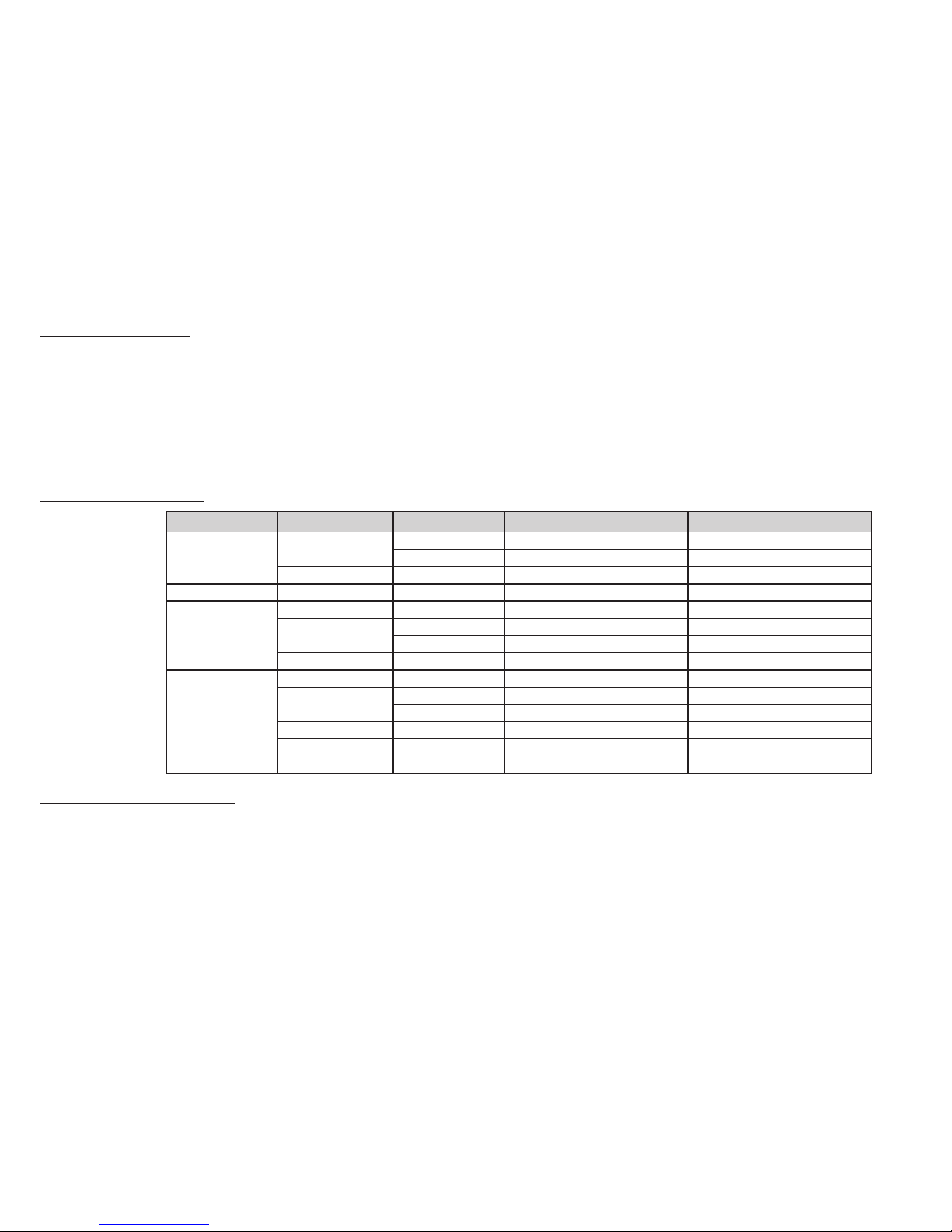
EWPlus 902 TERMINALS
OUT1 regulator relay OUT1
N-L Power Supply (115Va or 230Va)
A TTL input
EWPlus 961 TERMINALS
Compressor relay
N-L Power Supply (115Va or 230Va)
A TTL input
EWPlus 961EWPlus 902
N
L
3 6 7 9
10
D.I.
Power Supply
4VA max
Pb1
4 5 11
(thermostat)
LOAD
OUT1
A
TTL
W
PLU
S
902
N
L
2 3 9
10
D.I.
Pb1
4 11
(A)
(thermostat)
A
TTL
W
PLU
S
961
Power Supply
4VA max
Page 19
19
CONNECTIONS
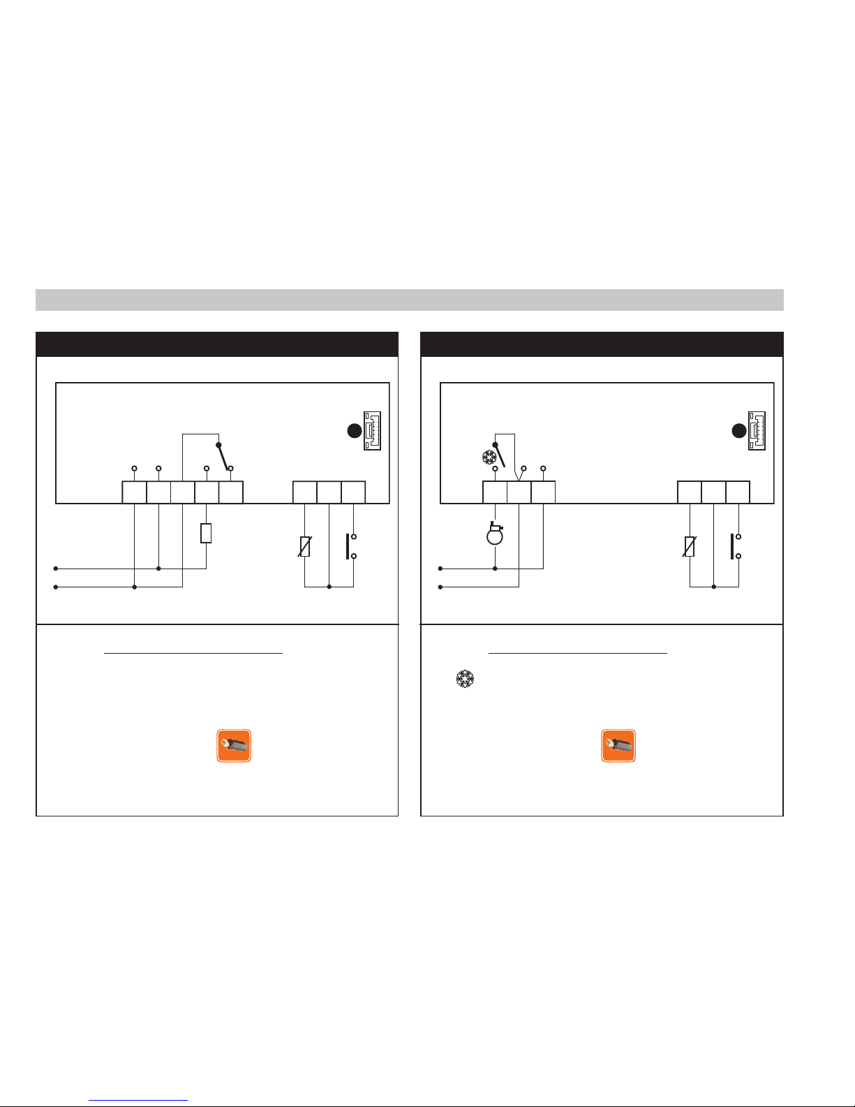
EWPlus 971 TERMINALS
Compressor relay
Defrost relay
N-L Power Supply (115Va or 230Va)
A TTL input
EWPlus 974 TERMINALS
Compressor relay
Defrost relay
Fans relay
N-L Power Supply (115Va or 230Va)
A TTL input
EWPlus 974EWPlus 971
N
L
2 3 6 7 8 9
10
D.I.
Pb1
4 5 11
Pb2
(A) (B)
(evaporator)
(thermostat)
A
TTL
W
PLU
S
971
Power Supply
4VA max
1
N
L
2 3 6 7 8 9
10
(C)
D.I.
Pb1
4 5 11
Pb2
(A) (B)
(evaporator)
(thermostat)
A
TTL
W
PLU
S
974
Power Supply
4VA max
Page 20
20
Parameters - Default setting
PAR
EWPlus 902/961 EWPlus 971 EWPlus 974
M.U. Level
RANGE DEFAULT RANGE DEFAULT RANGE DEFAULT
SEt -50,0 ... 99,0 32,0 -50,0 ... 99,0 32,0 -50,0 ... 99,0 32,0 °C/°F
diF 0,1 ... 30,0 2,0 0,1 ... 30,0 2,0 0,1 ... 30,0 2,0 °C/°F 1&2
HSE LSE ... 230 99,0 LSE ... 230 99,0 LSE ... 230 99,0 °C/°F 1&2
LSE -55,0 ... HSE -50,0 -55,0 ... HSE -50,0 -55,0 ... HSE -50,0 °C/°F 1&2
HC H/C C flag 2
OSP -30,0 ... 30,0 0,0 -30,0 ... 30,0 0,0 -30,0 ... 30,0 0,0 °C/°F 2
dOd n/y n n/y n n/y n flag 2
dAd 0 ... 255 0 0 ... 255 0 0 ... 255 0 min 2
Ont 0 ... 250 0 0 ... 250 0 0 ... 250 0 min 2
OFt 0 ... 250 1 0 ... 250 1 0 ... 250 1 min 2
dOn 0 ... 250 0 0 ... 250 0 0 ... 250 0 secs 2
dOF 0 ... 250 0 0 ... 250 0 0 ... 250 0 min 2
dbi 0 ... 250 0 0 ... 250 0 0 ... 250 0 min 2
OdO 0 ... 250 0 0 ... 250 0 0 ... 250 0 min 2
dty 0/1/2 0 0/1/2 0 flag 1&2
dit 0 ... 250 6 0 ... 250 6 0 to 250 6 hours 1&2
dCt 0/1/2 1 0/1/2 1 0/1/2 1 num 2
dOH 0 ... 59 0 0 ... 59 0 0 ... 59 0 min 2
dEt 1 ... 250 30 1 ... 250 30 1 ... 250 30 min 1&2
dSt -50,0 ... 150 45,0 -50,0 ... 150 45,0 °C/°F 1&2
dPO n/y n n/y n n/y n flag 2
FPt 0/1 0 flag 2
FSt -50,0 ... 150 100,0 °C/°F 1&2
FAd 1,0 ... 50,0 2,0 °C/°F 2
Fdt 0 ... 250 0 min 1&2
dt 0 ... 250 0 0 ... 250 0 min 1&2
dFd n/y y flag 1&2
FCO n/y y flag 2
Fod n/y n flag 2
Att 0/1 1 0/1 1 0/1 1 flag 2
AFd 1,0 ... 50,0 2,0 1,0 ... 50,0 2,0 1,0 ... 50,0 2,0 °C/°F 2
Page 21
21
PAR
EWPlus 902/961 EWPlus 971 EWPlus 974
M.U. Level
RANGE DEFAULT RANGE DEFAULT RANGE DEFAULT
HAL LAL ... 150,0 50,0 LAL ... +150,0 50,0 LAL ... 150,0 50,0 °C/°F 1&2
LAL -50,0 ... HAL -50,0 -50,0 ... HAL -50,0 -50,0 ... HAL -50,0 °C/°F 1&2
PAO 0 ... 10 0 0 ... 10 0 0 ... 10 0 hours 2
dAO 0 ... 999 0 0 ... 999 0 0 ... 999 0 min 2
0AO 0 ... 10 0 0 ... 10 0 0 ... 10 0 hours 2
tdO 0 ... 250 0 0 ... 250 0 0 ... 250 0 min 2
tAO 0 ... 250 0 0 ... 250 0 0 ... 250 0 min 1&2
dAt n/y n n/y n flag 2
EAL n/y n n/y n n/y n flag 2
dEA 0 ... 14 0 0 ... 14 0 0 ... 14 0 num 2
FAA 0 ... 14 0 0 ... 14 0 0 ... 14 0 num 2
LOC n/y n n/y n n/y n flag 1&2
PS1 0 ... 250 0 0 ... 250 0 0 ... 250 0 núm 1&2
PS2 0 ... 250 0 0 ... 250 0 0 ... 250 0 num 2
ndt n/y y n/y y n/y y flag 2
CA1 -12,0 ... 12,0 0,0 -12,0 ... 12,0 0,0 -12,0 ... 12,0 0,0 °C/°F 1&2
CA2 -12,0 ... 12,0 0,0 -12,0 ... 12,0 0,0 °C/°F 1&2
ddL 0/1/2 1 0/1/2 1 0/1/2 1 num 1&2
dro 0/1 1 0/1 1 0/1 1 flag 2
ddd 0/1/2 1 0/1/2 1 0/1/2 1 num 2
H08 0/1/2 2 0/1/2 2 0/1/2 2 num 2
H11 -6 ... +6 0 -6 ... +6 0 -6 ... +6 0 num 2
H22 0 ... 6 2 num 2
H23 0 ... 6 3 num 2
H25(!) 0 ... 6 4 num 2
H32 0 ... 4 0 0 ... 4 0 0 ... 4 0 num 2
H42 n/y y n/y y flag 1&2
rEL / / / / / / / 1&2
tAb / / / / / / / 1&2
UL / / / / / / / 2
Fr / / / / / / / 2
(!) WARNING!
Parameter H25 is present only in model with buzzer on board.
Page 22

22
ELECTRICAL WIRING
Attention! Never work on electrical connections when the machine is switched on.
The device is equipped with screw or removable terminals for connecting electric cables with a diameter of
13 AWG (2.5mm2) (one wire per terminal for power connections).
For the capacity of the terminals, see the label on the instrument. Do not exceed the maximum current allowed;
in case of higher loads, use an appropriate contactor. Make sure the power supply voltage complies with the
one required by the instrument. Probes have no connection polarity and can be extended using a regular
bipolar cable (note that the extension of the probes affects the EMC electromagnetic compatibility of the
instrument: pay extreme attention to wiring). Probe cables, power supply cables and TTL serial cables should
be separated from, and not placed near power cables.
RESPONSIBILITY AND RESIDUAL RISKS
In addition to the exclusions provided in the Warranty terms, Invensys Controls shall not be liable for any
damages deriving from:
- Installation and/or use other than that prescribed and, in particular, that does not comply with applicable
regulatory and safety standards, including the standards provided herein;
- Installation and/or use on boards which do not guarantee adequate protection against electric shock,
water, dust, or access to dangerous parts;
- Installation and/or use on boards that do not comply with applicable regulatory and safety standards;
- tampering with and/or alteration of the products.
DISCLAIMER
This manual and its contents remain the sole property of Robertshaw Controls Company, d/b/a Invensys
Controls, and shall not be reproduced or distributed without the written permission of an authorized
representative of Invensys Controls. Although considerable care has been exercised in the preparation of this
document, Invensys Controls, its employees, agents, vendors, and any other third parties cannot and do not
accept any liability whatsoever in connection with its use, preparation, editing, or any misprints and errors
contained herein. Invensys Controls reserves the right to make changes to this document at any time without
prior notice.
Page 23

23
WARRANTY ON EWPLUS 902/961/971/974 SERIES
Eighteen Months Limited Warranty
Invensys Controls warrants to the original contractor installer, or to the original consumer user, that each new
Eliwell Control will be free from defects in materials and workmanship under normal use and service for a
period of eighteen (18) months from the date of manufacture (the “Warranty Period”). If any Product fails within
the applicable Warranty Period, Invensys Controls shall, at its option, repair or replace the Product or credit
the purchase price, provided the Product is returned to Invensys Controls’ facility or designated agent within
the Warranty Period, with transportation or postage charges prepaid and proof of the date of purchase, and
the Product, upon examination by Invensys Controls, is found not to conform to the Warranty. Cost of Product
removal, labor, or reinstallation of new Product are not covered under this Warranty and are not the responsibility
of Invensys Controls. Warranty on Products, parts and/or components sold, but not manufactured by Invensys
Controls, shall be expressly limited to the warranty terms of the manufacturer of such products, parts and/or
components.
The above warranty does not apply to: i) batteries; ii) defects or damage that result from use of the Products in
other than their normal and customary manner; iii) defects or damage that result from use of the Products in
any manner other than in accordance with Invensys Controls’ recommendations and instructions; iv) defects or
damage which occur from misuse, alteration, accident, water, fire or neglect; and/or v) defects due to abuse or
damage such as burned contacts, stripped threads, split castings, improper installation or missing parts.
THE FOREGOING WARRANTY IS IN LIEU OF AND EXCLUDES ALL OTHER WARRANTIES, WHETHER
EXPRESS OR IMPLIED, INCLUDING THE IMPLIED WARRANTIES OF MERCHANTABILITY, TITLE AND FITNESS
FOR A PARTICULAR PURPOSE. IN NO EVENT SHALL INVENSYS CONTROLS BE LIABLE TO CONSUMER,
CONTRACTOR OR ANY THIRD PARTY FOR ANY CONSEQUENTIAL, INCIDENTIAL, SPECIAL, EXEMPLARY, OR
PUNITIVE DAMAGES ARISING FROM OR RELATING TO USE OF THE PRODUCT INCLUDING, BUT NOT LIMITED
TO, LOSS OF GOODWILL, LOSS OF PROFIT OR REVENUE, AND PROPERTY DAMAGE, REGARDLESS WHETHER
SUCH LOSS OR DAMAGE IS BASED IN CONTRACT, WARRANTY, TORT, NEGLIGENCE, STRICT LIABILITY,
INDEMNITY, PRODUCT LIABILITY, OR OTHERWISE AND EVEN IF INVENSYS CONTROLS HAS BEEN ADVISED
OF THE POSSIBILITY OF SUCH DAMAGES.
Page 24

24
WARRANTY ON EWPLUS 902/961/971/974 SERIES (Cont.)
REPAIR, REPLACEMENT, OR CREDIT OF THE PURCHASE PRICE, AS PROVIDED HEREIN, SHALL CONSTITUTE
BUYER’S SOLE RIGHTS AND REMEDIES WITH RESPECT TO DEFECTS IN THE PRODUCTS.
Some states do not allow the exclusion or limitation of incidental or consequential damages, or allow limitations
on how long an implied warranty lasts, so the above limitations or exclusions may not apply to you. This Warranty
gives you specific legal rights, and you may also have other rights which vary from state to state.
For Warranty returns, send controls, shipping prepaid and proof of date of purchase to:
Invensys Controls
Warranty Claims Department
515 S. Promenade
Corona, CA 91719
In Canada:
Invensys Controls
Warranty Claims Department
3505 Laird Road Unit #14
Mississauga, Ontario L5L 5Y7 Canada
Page 25

25
Controles electrónicos para unidades de refrigeración
STAND-BY (ESC)
Pulsar y soltar
Regresa a un nivel anterior respecto al
menú actual
Confirma el valor del parámetro
Pulsar durante al menos 5 s
Activa la función Stand-by
(cuando no estoy dentro del menú)
Subir
Pulsar y soltar
Recorre las opciones del menú
Aumenta los valores
Pulsar durante al menos 5 s
Activa la función de descarche manual
Bajar
Pulsar y soltar
Recorre las opciones del menú
Aumenta los valores
Pulsar durante al menos 5 s
Función configurable por el usuario
(par. H32)
SET (ENTER)
Pulsar y soltar
Muestras las alarmas (si las hay)
Entra en el menú Estado Máquina
Pulsar durante al menos 5 s
Entra en el menú Programación
Confirma los mandos
set
TECLAS
EW
PLUS
902/961
EW
PLUS
971/974
ESPAÑOL
Page 26
26
LED
SET Reducido / Economy
Intermitente: set reducido activado
Intermitente rápido: encendido con
parámetros de nivel 2
Off: en caso contrario
Led Compresor
Encendido fijo: compresor activado
Intermitente: retardo, protección o
activación bloqueada
Off: en caso contrario
Led Defrost (Descarche)
Encendido fijo: descarche activado
Intermitente: activación manual o desde E.D.
Off: en caso contrario
Led Ventilador
Encendido fijo: ventiladores activados
Off: en caso contrario
(sólo EWPlus 971 y EWPlus 974)
Led Alarma
Encendido fijo: presencia de una alarma
Intermitente: alarma silenciada
Off: en caso contrario
Led Estado HEAT
Encendido fijo: compresor en HEAT
Off: en caso contrario
(sólo EWPlus 902 y EWPlus 961)
NO UTILIZADO
(sólo EWPlus 902 y EWPlus 961)
Led Aux
Encendido fijo: salida Aux activada*
*según el modelo
(sólo EWPlus 971 y EWPlus 974)
Led °C
Encendido fijo: configuración en °C (dro = 0)
Off: en caso contrario
Led °F
Encendido fijo: configuración en °F (dro = 1)
Off: en caso contrario
Nota:
Si el instrumento está programado en modalidad Frío
(COOL), para poderlo utilizar en modalidad Calor
(HEAT) es necesario reprogramarlo con la Copy Card
debidamente configurada.
Lo mismo ocurre para pasar de Calor a Frío.
Page 27
27
ACCESO Y USO DE LOS MENÚS
Los recursos están agrupados en dos menús a los que se accede como se indica a continuación:
• Menú “Estado Máquina”: pulsar y soltar la tecla
set
.
• Menú “Programación”: pulsar la tecla
set
durante más de 5 segundos.
Esperar 15 segundos sin utilizar el teclado (tiempo máximo) o pulsar una vez la tecla para confirmar el
último valor que aparece en el display y regresar a la página anterior.
MENÚ ESTADO MÁQUINA
Pulsar y soltar la tecla
set
para entrar en el menú “Estado Máquina”. Si no hay ninguna alarma activada, se
visualiza la etiqueta “SEt”. Pulsar las teclas
y para recorrer las carpetas del menú “Estado Máquina”:
- AL: carpeta de alarmas (sólo se visualiza si hay alarmas activadas);
- SEt: carpeta de configuración
- Pb1: carpeta del valor de la sonda 1;
- Pb2: carpeta del valor de la sonda 2 **;
(** sólo modelos EWPlus 971 y EWPlus 974)
Configurar el Setpoint: Para ver el valor del Setpoint, pulsar la tecla
set
mientras se visualiza la etiqueta
“SEt”. El valor del Setpoint aparecerá en el display. Para modificar el valor del
Setpoint, pulsar las teclas y antes de que transcurran 15 s. Para confirmar la
modificación, pulsar
set
.
Ver las sondas: Desde las etiquetas Pb1 o Pb2*, pulsar la tecla
set
para ver el valor medido por la
sonda asociada (* Pb2 sólo se visualiza en los modelos EWPlus 971 y EWPlus 974).
BLOQUEO DE MODIFICACIÓN DEL SETPOINT
El instrumento permite desactivar el funcionamiento del teclado.
El teclado se puede bloquear programando el parámetro “LOC”. Aunque el teclado esté bloqueado, es
posible acceder al menú “Estado Máquina” pulsando la tecla
set
y ver el Setpoint. El valor no se podrá
modificar. Para desbloquear el teclado, repetir el procedimiento de bloqueo.
set
set
set set
Page 28
28
MENÚ DE PROGRAMACIÓN
Para entrar en el menú de “Programación”, pulsar durante más de 5 s la tecla
set
. Si está activada, el sistema
solicitará la CONTRASEÑA de acceso “PA1” para mostrar los parámetros de nivel 1 y “PA2” para mostrar los de
nivel 2 (ver apartado “CONTRASEÑA”). Al entrar en el menú, el display mostrará el primer parámetro (“diF”).
Pulsar las teclas
y para recorrer todos los parámetros del nivel actual:
5 sec
Seleccionar el parámetro deseado con las teclas y . Pulsar la tecla
set
para ver el valor actual del
parámetro. Utilizar las teclas y para modificar el valor y pulsar la tecla
set
para guardarlo.
NOTA: se recomienda apagar y volver a encender el instrumento siempre que se modifique la configuración de
los parámetros para evitar anomalías de funcionamiento en la configuración y/o los temporizadores activados.
CONTRASEÑA
Contraseña “PA1”: Autoriza el acceso a los parámetros de nivel 1. En la configuración estándar la contraseña
no está habilitada (valor = 0). Para habilitarla (valor ≠ 0) entrar en el menú Programación, pulsar las teclas y
para recorrer los parámetros hasta seleccionar la etiqueta “PS1”, pulsar
set
para ver el valor, modificarlo con
las teclas y y pulsar
set
para guardarlo. Si la contraseña está habilitada, el sistema la solicitará al entrar en
el menú “Programación”. Para introducirla, seguir la secuencia:
Contraseña “PA2”: Autoriza el acceso a los parámetros de nivel 2. En la configuración estándar está habilitada
(valor ≠ 0). Para modificar el valor, seguir las operaciones descritas para “PA1” y cambiar el valor del parámetro
“PS2”. La visibilidad de “PA2” es:
1) Si PA1 y PA2 ≠ 0: Pulsando la tecla
set
durante más de 5 s, “PA1” y “PA2” se visualizarán en el mismo nivel y será
posible acceder a los parámetros de nivel 1 o de nivel 2.
2) En los demás casos: La contraseña “PA2” se encuentra entre los parámetros de nivel 1. Si está habilitada, será
solicitada para acceder al nivel 2. Para introducirla, realizar las operaciones descritas para la contraseña “PA1”.
Si la contraseña introducida es incorrecta, el instrumento muestra la etiqueta PA1/PA2 y es necesario repetir la
secuencia de introducción.
set
setset
set
set
set
Page 29

29
ALARMAS
Etiqueta Avería Causa Efectos Soluciones
E1
Sonda1 averiada
(cámara)
• Lectura de valores fuera del rango de
funcionamiento
• Sonda averiada / en cortocircuito
/ abierta
• Visualización de etiqueta E1
• Icono de alarma fijo
• Desactivación del control de alarma de
máxima y mínima
• Funcionamiento del compresor según
los parámetros “Ont” y “OFt”.
• Controlar el tipo de sonda (NTC)
• Controlar el cableado de las
sondas
• Sustituir la sonda
E2
Sonda2 averiada
(descarche)
• Lectura de valores fuera del rango de
funcionamiento
• Sonda averiada / en cortocircuito
/ abierta
• Visualización de etiqueta E2
• Icono de alarma fijo
• El ciclo de descarche termina por tiempo
máximo (parámetro “dEt”)
• Controlar el tipo de sonda (NTC)
• Controlar el cableado de las
sondas
• Sustituir la sonda
AH1
Alarma de ALTA
temperatura de la
sonda 1
Valor leído por Pb1 > HAL transcurrido
un tiempo equivalente a “tAO”
(ver “ALARMAS DE TEMP. MÁX. Y MÍN.)
• Registro de etiqueta AH1 en carpeta AL
• Sin efecto sobre la regulación
• Esperar a que el valor de
temperatura leído por la sonda 1
descienda por debajo de HAL
AL1
Alarma de BAJA
temperatura de la
sonda 1
Valor leído por Pb1 > LAL transcurrido
un tiempo equivalente a “tAO”
(ver “ALARMAS DE TEMP. MÁX. Y MÍN.)
• Registro de etiqueta AL1 en carpeta AL
• Sin efecto sobre la regulación
• Esperar a que el valor de
temperatura leído por la sonda 1
descienda por debajo de LAL
EA Alarma exterior
• Activación de la entrada digital
(H11 = ±5)
• Registro de etiqueta EA en carpeta AL
• Icono de alarma fijo
• Bloqueo de la regulación si EAL = y
• Comprobar y eliminar la causa
externa que ha generado la
alarma en la E.D.
OPd
Alarma puerta
abierta
• Activación de la entrada digital
(H11 = ±4) (durante un periodo de
tiempo mayor que tdO)
• Registro de etiqueta Opd en carpeta AL
• Icono de alarma fijo
• Bloqueo del control
• Cerrar la puerta
• Función de retardo definida
por OAO
Ad2
Descarche por
tiempo máximo
• Fin de descarche por tiempo en
lugar de por temperatura de fin de
descarche medida por la sonda Pb2
• Registro de etiqueta dAt en carpeta AL
• Icono de alarma fijo
• Esperar el descarche sucesivo para
restablecimiento automático
Page 30

30
74 mm
32 mm
29 mm
71 mm
70 mm
59 mm
ACTIVACIÓN MANUAL DEL CICLO DE DESCARCHE
La activación manual del ciclo de descarche se obtiene manteniendo pulsada durante 5 s la tecla .
Si no se dan las condiciones de descarche necesarias:
- El parámetro OdO ≠ 0 (EWPlus 902/961/971/974)
- La temperatura de la sonda del evaporador Pb2 supera la temperatura final de descarche (EWPlus 971/974)
el display parpadeará 3 veces para indicar que el descarche no será efectuado.
DIAGNÓSTICO
En caso de alarma el zumbador (si lo hay) se activa y el icono de alarma se enciende.
Para silenciar el zumbador, pulsar y soltar una tecla cualquiera. El icono de alarma seguirá parpadeando.
NOTAS: Durante los tiempos de inhabilitación de alarmas (carpeta “AL” de la Tabla de Parámetros), la alarma
no es señalizada.
El aviso E1 de alarma por sonda 1 averiada (Pb1) aparece directamente
en el instrumento.
Modelos EWPlus 971/974: El aviso de alarma por sonda 2 averiada
(Pb2) aparece directamente en el instrumento.
INSTALACIÓN
El instrumento ha sido diseñado para la instalación en panel. Realice un orificio de 2-13/16” x 1-1/8”
(71x29mm), introduzca el instrumento y fíjelo con los soportes que se suministran. No instale el instrumento
en lugares excesivamente húmedos y/o sucios, es adecuado para el uso en ambientes con polución ordinaria
o normal. La zona próxima a las ranuras de refrigeración del instrumento ha de estar bien ventilada.
Page 31

31
CÓMO UTILIZAR LA COPY CARD
La Copy Card es un accesorio que, conectándolo a un puerto de serie de tipo TTL, permite programar de modo
rápido los parámetros del instrumento (cargar y descargar un mapa de parámetros en uno o más instrumentos
del mismo tipo). Para cargar (etiqueta UL) y formatear la Copy Card (etiqueta Fr), es necesario efectuar las
siguientes operaciones:
Introducir la contraseña “PA2” y recorrer las opciones con las teclas y para seleccionar la función
deseada (por ejemplo UL). Pulsar la tecla
set
para iniciar la descarga.
Si el proceso termina con éxito, el display mostrará “y”; en caso de error, mostrará “n”.
Cargar (UL) Esta operación sirve para cargar los parámetros de programación desde el instrumento.
CARGAR: instrumento
Copy Card
Formato: (Fr)
Este comando sirve para formatear la Copy Card. Se recomienda efectuar esta operación cuando la
Copy Card se utiliza por primera vez. Atención: si el parámetro “Fr” se utiliza cuando la Copy Card
ya está programada, todos los parámetros que contiene serán cancelados. Esta operación no se
puede anular.
Descarga mediante reset:
Conectar la Copy Card al instrumento mientras está apagado.
Al encenderlo, el proceso de descarga desde la Copy Card
se iniciará en automático. Una vez completado el test de las
lámparas, el display mostrará “dLy” si el proceso termina
con éxito y “dLn” en caso de error.
DESCARGA: Copy Card
instrumento
NOTAS: Una vez completado el proceso de descarga, el instrumento utilizará las configuraciones del nuevo
mapa que se acaba de cargar.
UPLOAD
DOWNLOAD
set
Page 32

32
ALARMA DE TEMPERATURA MÁX. Y MÍN.
Temperatura en Valor
Relativo al Setpoint (Att=1)
Temperatura en Valor
Absoluto (Att=0)
Temp. ≤ Set + LAL *
Temp. ≥ Set + HAL **
Temp. ≥ Set + LAL + AFd o
≥ Set - ILALI + AFd (LAL < 0)
Temp. ≤ Set + HAL - AFd (HAL > 0)
Temp. ≤ ( con signo)
Temp. ≥ HAL (HAL con signo)
Temp. ≥ LAL + AFd
Temp. ≤ HAL - AFd
Alarma de
temperatura mínima
Alarma de
temperatura máxima
Restablecimiento
tras alarma de
temperatura mínima
Restablecimiento tras
temperatura máxima
* si LAL es negativo, Set + LAL < Set
** si HAL es negativo, Set + HAL < Set
Setpoint - LAL
AFd
Off
Setpoint + HAL
AFd
Setpoint - LAL + AFd
Setpoint + HAL - AFd
Setpoint
LAL
AFd
HAL
AFd
LAL + AFd
HAL - AFd
Page 33

33
CONDICIONES DE USO
Uso permitido
Con el fin de lograr una mayor seguridad, el instrumento debe instalarse y utilizarse según las instrucciones
suministradas y en condiciones normales no deberán ser accesibles las piezas con tensiones peligrosas. El
dispositivo debe estar protegido adecuadamente contra el agua y el polvo según su aplicación y ser accesible
sólo con el uso de una herramienta (con excepción del frontal). El dispositivo es idóneo para equipos
refrigerantes de uso doméstico y/o similares y su seguridad se ha verificado según las normas armonizadas
europeas de referencia.
Uso no permitido
Está totalmente prohibido cualquier otro uso distinto del permitido. Se debe tener en cuenta que los
contactos de relé suministrados son de tipo funcional y pueden averiarse: los dispositivos de protección
previstos por la normativa del producto o bien sugeridos por el sentido común, según específicas exigencias
de seguridad, deben estar instalados fuera del instrumento.
DATOS TÉCNICOS
Clasificación: Dispositivo de funcionamiento (no de seguridad) para incorporar
Instalación: Sobre panel con plantilla de montaje 2-13/16” x 1-1/8” (71x29mm).
Tipo de acción: 1.B
Grado de contaminación: 2
Grupo de material: IIIa
Categoría de sobretensión: II
Tensión impulsiva nominal: 2500 V
Temperatura: Uso: –5 a +65°C (+23 a +149°F) - Almacenamiento: –30 a +85°C (–22 a +185°F)
Alimentación eléctrica: 115Va or 230Va (
+
10% / -10%) 50/60 Hz
Consumo: 4VA máx.
Salidas digitales (relé): Consultar la etiqueta del dispositivo
Grado de resistencia al fuego: D
Clase del software: A
Nota: Controle la alimentación declarada en la etiqueta del instrumento; consulte con el departamento
comercial para obtener información sobre las capacidades de los relés y la alimentación.
Page 34

34
Características de las entradas
Rango de visualización: NTC –50°C a +110°C (–58°C a +230°F)
(en el display con 3 dígitos + signo)
Precisión: Mejor del 0.5% del final de escala +1 dígito
Definición: 0.1°C (0.1°F hasta 199.9°C ; 1°F más allá)
Zumbador: SÍ (según el modelo)
Entradas analógicas: EWPlus 902/961: 1 entrada NTC - EWPlus 971/974: 2 entradas NTC
Entradas digitales: 1 entrada digital sin tensión
Características de las salidas
Salidas
digitales:
Modelo Relé Tipo de carga
Alimentación 115VA Alimentación 230VA
EWPlus 902:
OUT1 - N.A.
resistivo 8A 8A
motor 1/8 Hp 1/2 Hp
OUT1 - N.C. resistivo 6A 6A
EWPlus 961: compresor motor 16 FLA / 96 LRA 12 FLA / 72 LRA
EWPlus 971:
compresor motor 16 FLA / 96 LRA 12 FLA / 72 LRA
descarche - N.A.
resistivo 8A 8A
motor 1/8 Hp 1/2 Hp
descarche - N.C. resistivo 6A 6A
EWPlus 974:
compresor motor 16 FLA / 96 LRA 12 FLA / 72 LRA
descarche - N.A.
resistivo 8A 8A
motor 1/8 Hp 1/2 Hp
descarche - N.C. resistivo 6A 6A
ventiladores
resistivo 3A 3A
motor 1.4 FLA / 7.5 LRA 1.4 FLA / 7.5 LRA
Características mecánicas
Caja: Cuerpo plástico de resina PC UL94 V-0, cristal de policarbonato
Dimensiones: Frontal 2-15/16” x 1-1/4” (74x32mm), profundidad 2-15/16” (59mm) (bornes excluidos)
Bornes: De tornillo/extraíbles para cables con sección de 13 AWG
(2.5 mm2)
Conectores: TTL para conectar la Copy Card
Humedad: Funcionamiento / Almacenamiento: 10 a 90% HR (sin condensación)
Page 35

35
Normas
Compatibilidad Electromagnética: El dispositivo cumple los requisitos de la Directiva 2004/108/EC
Seguridad: El dispositivo cumple los requisitos de la Directiva 2006/95/EC
Seguridad alimentaria: El dispositivo cumple los siguientes requisitos de la Norma EN13485:
- idóneo para la conservación
- aplicacion: aire
- clase climática A
- clase de medición 1 en el rango de -25°C to 15°C (-13°F to 59°F) (*)
(*sólo y exclusivamente si se utilizan sondas Eliwell NTC)
NOTA: Las características técnicas inherentes a las medidas (rango, precisión, definición, etc.), que se incluyen en
el documento, se refieren al instrumento en sí mismo y no a los accesorios en dotación como, por ejemplo, las
sondas. Esto implica, por ejemplo, que el error introducido por la sonda se agrega al característico del instrumento.
TABLA DE PARÁMETROS
PAR. Niv. DESCRIPCIÓN
SEt
SEtpoint de regulación de la temperatura.
COMPRESOR
diF 1&2
diFferential. Diferencial de activación del relé del compresor; el compresor se apaga al alcanzar el valor
de Setpoint configurado (por indicación de la sonda Pb1) y se vuelve a encender cuando la temperatura
alcanza un valor equivalente al setpoint más el valor del diferencial. Nota: diF ≠ 0.
HSE 1&2
Higher SEt. Valor máximo de setpoint.
LSE 1&2
Lower SEt. Valor mínimo de setpoint.
HC 2
El control aplicará una modalidad de funcionamiento para CALOR (“H”) o para FRÍO (“C”)
OSP 2
Offset Set Point. Valor de temperatura que se ha de sumar algebraicamente al Set-Point si el set reducido
está habilitado (función Economy).
dOd 2
digital (input) Open door. Entrada digital que permite apagar los dispositivos. Válido si H11=±4
(microinterruptor de la puerta). n = no apagar los dispositivos; y = apagar los dispositivos.
dAd 2
digital (input) Activation delay. Tiempo de retardo para la activación de la entrada digital.
Ont 2
ON time (compressor). Tiempo de encendido del compresor por sonda averiada. Si OFt=1 y Ont=0, el
compresor permanece siempre apagado, si OFt=1 y Ont>0 funciona en modalidad duty cycle.
OFt 2
OFF time (compressor). Tiempo de apagado del compresor por sonda averiada. Si Ont=1 y OFt=0, el
compresor permanece siempre encendido, si Ont=1 y OFt>0 funciona en modalidad duty cycle.
Page 36

36
dOn 2 delay (at) On compressor. Tiempo de retardo para la activación del relé del compresor desde la llamada.
dOF 2
delay (after power) OFF. Tiempo de retardo tras el apagado; entre el apagado del relé del compresor
y el encendido sucesivo debe transcurrir el tiempo indicado.
dbi 2
delay between power-on. Tiempo de retardo entre encendidos; entre dos encendidos sucesivos del
compresor debe transcurrir el tiempo indicado.
OdO (!) 2
delay Output (from power) On. Tiempo de retardo para la activación de las salidas desde el
encendido del instrumento o tras un corte de corriente.
DESCARCHE
dty 1&2
defrost type. Tipo de descarche.
0 = descarche eléctrico - compresor apagado (OFF) durante el descarche;
1 = descarche con inversión de ciclo (gas caliente);
compresor encendido (ON) durante el descarche;
2 = descarche en modalidad Free; descarche independiente del compresor.
dit 1&2 defrost interval time. Intervalo de tiempo entre dos descarches sucesivos.
dCt 2
defrost Counting type. Selección del modo de cómputo del intervalo de descarche.
0 = horas de funcionamiento del compresor (método DIGIFROST®); Descarche activado SÓLO
con compresor encendido;
1 = Real Time - horas de funcionamiento del aparato; el cómputo de descarche permanece
siempre activado cuando la máquina está encendida y se inicia siempre al encenderla;
2 = parada compresor. Cada vez que el compresor se para se inicia un ciclo de descarche en
función del parámetro dty.
dOH 2 defrost Offset Hour. Tiempo de retardo para iniciar el primer descarche desde la llamada.
dEt 1&2
defrost Endurance time. Tiempo máximo de descarche; determina la duración máxima del descarche.
dSt 1&2
defrost Stop temperature. Temperatura de fin de descarche (determinada por la sonda del evaporador).
dPO 2
defrost (at) Power On. Determina si el instrumento debe iniciar el descarche al encenderlo (si la
temperatura medida lo permite). y = sí; n = no.
VENTILADORES EVAPORADOR
FPt 2
Fan Parameter type. Caracteriza el parámetro “FSt” que se puede expresar en valor absoluto de
temperatura o en valor relativo al Setpoint. 0 = absoluto; 1 = relativo.
FSt 1&2
Fan Stop temperature. Temperatura de bloqueo de los ventiladores; si el valor leído por la sonda
del evaporador supera el valor programado, los ventiladores se paran.
FAd 2 FAn differential. Diferencial de intervención para activación de los ventiladores (ver par. “FSt”).
Fdt 1&2 Fan delay time. Tiempo de retardo para la activación de los ventiladores tras un descarche.
Page 37

37
dt 1&2 drainage time. Tiempo de goteo.
dFd 1&2
defrost Fan disable. Permite seleccionar la desactivación de los ventiladores del evaporador durante
el descarche. y = sí (ventilador desactivado o apagado); n = no.
FCO 2
Fan Compressor OFF. Permite seleccionar el bloqueo de los ventiladores con el compresor OFF
(apagado). y = ventiladores activados (termostatación; en función del valor leído por la sonda de
descarche, ver el parámetro “FSt”); n = ventiladores apagados; dc = no utilizado;
Fod 2
Fan open door. Activación de los ventiladores si la puerta está abierta.
Permite seleccionar el bloqueo de los ventiladores con la puerta abierta y su activación al cerrarla (si
estaban activados). n = bloqueo ventiladores; y = ventiladores sin variación de estado.
ALARMAS
Att 2
Permite seleccionar si los parámetros HAL y LAL deben tener un valor absoluto (Att=0) o relativo
(Att=1).
AFd 2 Alarm Fan differential. Diferencial de alarmas.
HAL 1&2
Higher ALarm. Alarma de temperatura máxima. Valor de temperatura (en valor relativo) por encima
del cual se activa la señal de alarma.
LAL 1&2
Lower ALarm. Alarma de temperatura máxima. Valor de temperatura (en valor relativo) por debajo
del cual se activa la señal de alarma.
PAO 2
Power-on Alarm Override. Tiempo de desactivación de las alarmas al encender el instrumento tras
un corte de corriente.
dAO 2 defrost Alarm Override. Tiempo de desactivación de las alarmas de temperatura tras el descarche.
0AO 2
Retardo para la activación de la alarma tras la desactivación de la entrada digital (puerta cerrada).
Por alarma se entiende la alarma de alta y baja temperatura.
tdO 2 time out door Open. Tiempo de retardo para la activación de la alarma por puerta abierta.
tAO 1&2 temperature Alarm Override. Tiempo de retardo para la activación de la alarma de temperatura.
dAt 2
defrost Alarm time. Activación de alarma por fin de descarche por tiempo máximo.
n = no activar alarma; y = activar alarma.
EAL 2 External Alarm Clock. Una alarma externa bloquea los controles (n = no bloquear; y = bloquear).
COMUNICACIÓN
dEA 2 Índice del dispositivo dentro de la familia (valores válidos de 0 a 14).
FAA 2
Familia de dispositivo (valores válidos de 0 a 14). El par de valores FAA y dEA es la dirección de red
del dispositivo y posee el siguiente formato “FF.DD” (donde FF=FAA y DD=dEA).
Page 38

38
DISPLAY
LOC 1&2
LOCk. Bloqueo de modificación del Setpoint. Ver el apartado correspondiente. Es posible entrar
en la programación de parámetros y modificar incluso su estado para permitir el desbloqueo del
teclado. n = no; y = sí.
PS1 1&2
PAssword 1. Si está habilitada (valor distinto de 0), activa la contraseña de acceso a los parámetros
de nivel 1.
PS2 2
PAssword 2. Si está habilitada (valor distinto de 0), activa la contraseña de acceso a los parámetros
de nivel 2.
ndt 2 number display type. Visualización con punto decimal. y = sí; n = no.
CA1 1&2 Calibración 1. Valor de temperatura positivo o negativo que se suma al leído por la sonda 1.
CA2 1&2 Calibración 2. Valor de temperatura positivo o negativo que se suma al leído por la sonda 2.
ddL 1&2
Defrost display Lock. Modalidad de visualización durante el descarche.
0 = muestra la temperatura leída por la sonda de la cámara;
1 = bloquea la lectura en el valor de temperatura leído por la sonda de la cámara desde que se
activa el descarche y hasta que se alcanza el valor de Setpoint;
2 = muestra la etiqueta “dEF” durante el descarche y hasta que se alcanza el valor de Setpoint.
dro 2
Display read-out. Selecciona la unidad de visualización de la temperatura leída por la sonda en °C
o °F. (0 = °C, 1 = °F).
NOTA: al pasar de °C a °F y viceversa, NO se modifican los valores del setpoint, el diferencial,
etc. (por ejemplo set = 10 °C será 10 °F).
ddd 2
Selección del tipo de valor que ha de mostrar el display.
0 = Setpoint; 1 = sonda de la cámara (Pb1); 2 = sonda del evaporador (Pb2).
CONFIGURACIÓN
H08 (!) 2
Modalidad de funcionamiento en stand-by.
0 = apagar sólo el display;
1 = apagar el display, bloquear los controles y las alarmas;
2 = mostrar OFF en el display y bloquear los controles y las alarmas.
H11 (!) 2
Configuración de las entradas digitales y la polaridad.
0 = desactivado; ±1 = descarche; ±2 = set reducido; ±3 = no utilizado;
±4 = microinterruptor puerta; ±5 = alarma externa; ±6 = Stand-by (ON-OFF).
¡ATENCIÓN!: signo “+” indica que la entrada se activa con contacto cerrado.
signo “-” indica che la entrada se activa con contacto abierto.
Page 39

39
H22 (!) 2
(Solo EWPlus 971) Configuración salida digital 2 (B).
0=Deshabilitada; 1=Compressor; 2=Desescarghe; 3=Ventiladores; 4=Alarma; 5=AUX; 6=StandBy.
H23 (!) 2 (Solo EWPlus 974) Configuración salida digital 3 (C). Análogo a H21.
H25 (!) 2 (Opciòn) Activa/Desactiva el zumbador. 0 = Deshabilitada; 4 = Buzzer; 1-2-3-5-6 = No se utiliza.
H32 (!) 2
Configuración de la tecla DOWN.
0 = desactivada; 1 = descarche; 2 = no utilizada; 3 = set reducido; 4 = stand-by.
H42 (!) 1&2 Presencia de la sonda del evaporador. n = no presente; y = presente.
reL 1&2 reLease firmware. Versión de dispositivo: parámetro de solo lectura.
tAb 1&2 tAble of parameters. Reservado: parámetro de solo lectura.
COPY CARD
UL 2 Up Load. Envío de los parámetros de programación del instrumento a la Copy Card.
Fr 2 Format. Eliminación de todos los datos contenidos en la Copy Card.
(!) ¡ATENCIÓN!
• Cuando se modifica uno o más parámetros marcados con (!), es necesario apagar y volver a encender el
control para garantizar el funcionamiento correcto.
• El parámetro H25 sólo está presente en los modelos equipados con zumbador.
SUPERVISIÓN
El instrumento se puede conectar:
• al sistema de telegestión TelevisSystem (°)
• a un software de configuración rápida de los parámetros ParamManager
La conexión se efectúa a través de un puerto de serie TTL.
Para efectuar la conexión a la red RS-485, se debe utilizar la interfaz TTL/RS485 BusAdapter 150.
Para la conexión al PC, se debe utilizar:
• para TelevisSystem: PCInterface 1110/1120 con licencia Televis;
• para ParamManager: PCInterface 2150/2250 con licencia ParamManager;
(°) Para configurar el instrumento, se deben utilizar los parámetros “dEA” y “FAA” del menú “Programación”.
NOTA: El instrumento se puede conectar a TelevisSystem pero la función RVD no estará disponible.
Page 40

40
CONEXIONES
BORNES EWPlus 902
OUT1 relé del control OUT1
N-L Alimentación (115Va o 230Va)
A Entrada TTL
BORNES EWPlus 961
Relé del compresor
N-L Alimentación (115Va o 230Va)
A Entrada TTL
EWPlus 961EWPlus 902
N
L
3 6 7 9
10
D.I.
Alimentación
4VA máx
Pb1
4 5 11
(cámara)
CARGA
OUT1
A
TTL
W
PLU
S
902
N
L
2 3 9
10
D.I.
Pb1
4 11
(A)
(cámara)
A
TTL
W
PLU
S
961
Alimentación
4VA máx
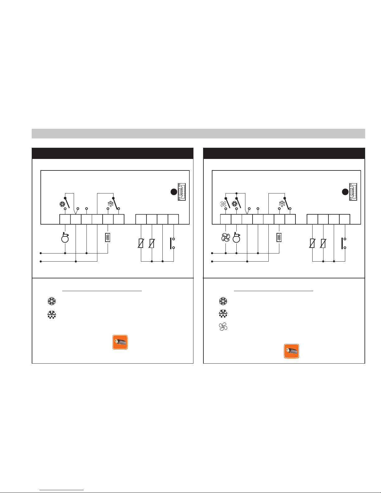
Page 41

41
CONEXIONES
BORNES EWPlus 971
Relé del compresor
Relé de descarche
N-L Alimentación (115Va o 230Va)
A Entrada TTL
BORNES EWPlus 974
Relé del compresor
Relé de descarche
Relé de los ventiladores
N-L Alimentación (115Va o 230Va)
A Entrada TTL
EWPlus 974EWPlus 971
N
L
2 3 6 7 8 9
10
D.I.
Pb1
4 5 11
Pb2
(A) (B)
(descarche)
(cámara)
A
TTL
W
PLU
S
971
Alimentación
4VA máx
1
N
L
2 3 6 7 8 9
10
(C)
D.I.
Pb1
4 5 11
Pb2
(A) (B)
(descarche)
(cámara)
A
TTL
W
PLU
S
974
Alimentación
4VA máx
Page 42

42
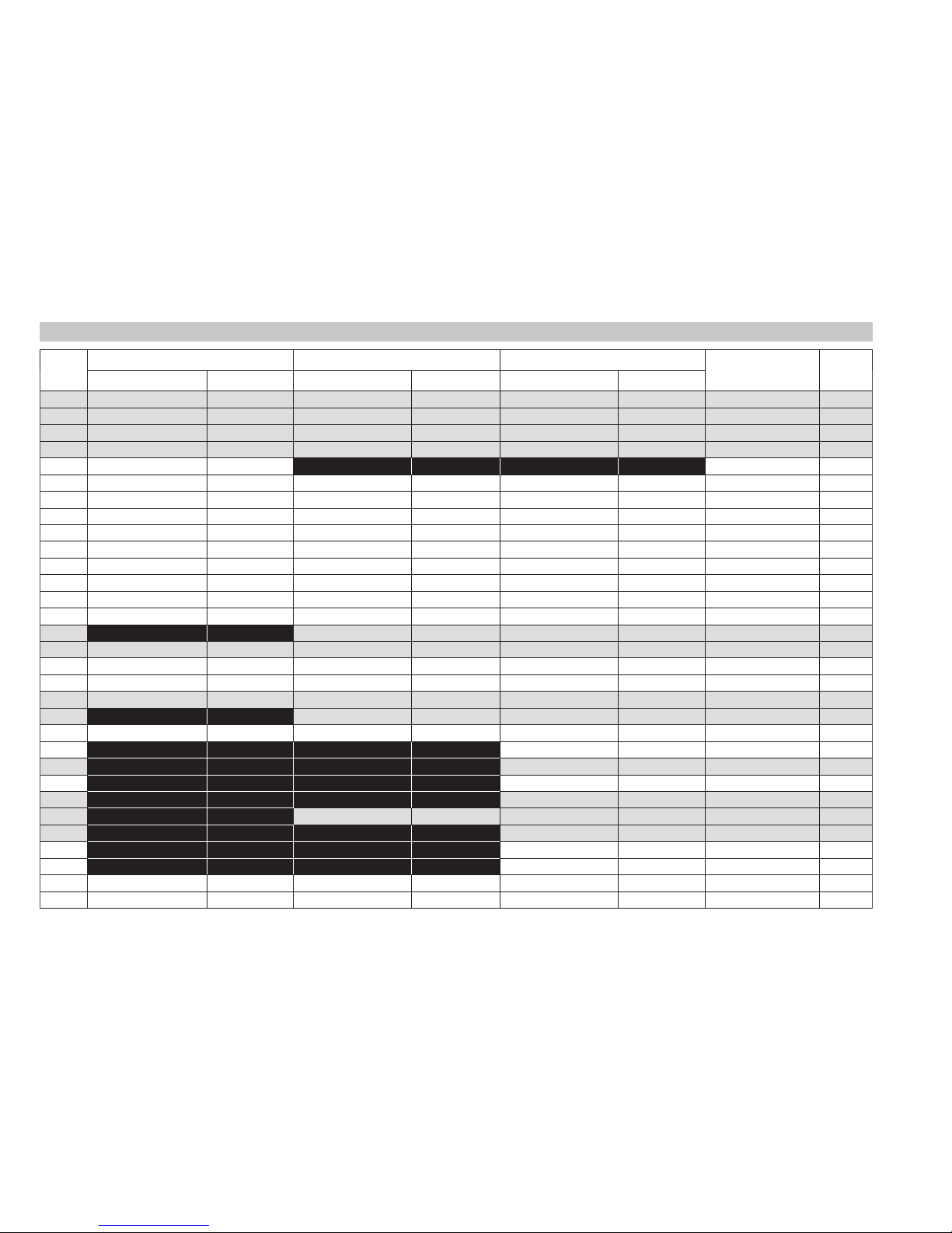
Parámetros - Ajuste predefinido
PAR
EWPlus 902/961 EWPlus 971 EWPlus 974
U.M. Nivel
RANGO PREDEFINIDO RANGO PREDEFINIDO RANGO PREDEFINIDO
SEt -50,0 ... 99,0 32,0 -50,0 ... 99,0 32,0 -50,0 ... 99,0 32,0 °C/°F
diF 0,1 ... 30,0 2,0 0,1 ... 30,0 2,0 0,1 ... 30,0 2,0 °C/°F 1&2
HSE LSE ... 230 99,0 LSE ... 230 99,0 LSE ... 230 99,0 °C/°F 1&2
LSE -55,0 ... HSE -50,0 -55,0 ... HSE -50,0 -55,0 ... HSE -50,0 °C/°F 1&2
HC H/C C flag 2
OSP -30,0 ... 30,0 0,0 -30,0 ... 30,0 0,0 -30,0 ... 30,0 0,0 °C/°F 2
dOd n/y n n/y n n/y n flag 2
dAd 0 ... 255 0 0 ... 255 0 0 ... 255 0 min. 2
Ont 0 ... 250 0 0 ... 250 0 0 ... 250 0 min. 2
OFt 0 ... 250 1 0 ... 250 1 0 ... 250 1 min. 2
dOn 0 ... 250 0 0 ... 250 0 0 ... 250 0 sec 2
dOF 0 ... 250 0 0 ... 250 0 0 ... 250 0 min. 2
dbi 0 ... 250 0 0 ... 250 0 0 ... 250 0 min. 2
OdO 0 ... 250 0 0 ... 250 0 0 ... 250 0 min. 2
dty 0/1/2 0 0/1/2 0 flag 1&2
dit 0 ... 250 6 0 ... 250 6 0 ... 250 6 horas 1&2
dCt 0/1/2 1 0/1/2 1 0/1/2 1 núm. 2
dOH 0 ... 59 0 0 ... 59 0 0 ... 59 0 min. 2
dEt 1 ... 250 30 1 ... 250 30 1 ... 250 30 min. 1&2
dSt -50,0 ... 150 45,0 -50,0 ... 150 45,0 °C/°F 1&2
dPO n/y n n/y n n/y n flag 2
FPt 0/1 0 flag 2
FSt -50,0 ... 150 100,0 °C/°F 1&2
FAd 1,0 ... 50,0 2,0 °C/°F 2
Fdt 0 ... 250 0 min. 1&2
dt 0 ... 250 0 0 ... 250 0 min. 1&2
dFd n/y y flag 1&2
FCO n/y y flag 2
Fod n/y n flag 2
Att 0/1 1 0/1 1 0/1 1 flag 2
AFd 1,0 ... 50,0 2,0 1,0 ... 50,0 2,0 1,0 ... 50,0 2,0 °C/°F 2
Page 43

43
PAR
EWPlus 902/961 EWPlus 971 EWPlus 974
U.M. Nivel
RANGO PREDEFINIDO RANGO PREDEFINIDO RANGO PREDEFINIDO
HAL LAL ... 150,0 50,0 LAL ... 150,0 50,0 LAL ... 150,0 50,0 °C/°F 1&2
LAL -50,0 ... HAL -50,0 -50,0 ... HAL -50,0 -50,0 ... HAL -50,0 °C/°F 1&2
PAO 0 ... 10 0 0 ... 10 0 0 ... 10 0 horas 2
dAO 0 ... 999 0 0 ... 999 0 0 ... 999 0 min. 2
0AO 0 ... 10 0 0 ... 10 0 0 ... 10 0 horas 2
tdO 0 ... 250 0 0 ... 250 0 0 ... 250 0 min. 2
tAO 0 ... 250 0 0 ... 250 0 0 ... 250 0 min. 1&2
dAt n/y n n/y n flag 2
EAL n/y n n/y n n/y n flag 2
dEA 0 ... 14 0 0 ... 14 0 0 ... 14 0 núm. 2
FAA 0 ... 14 0 0 ... 14 0 0 ...14 0 núm. 2
LOC n/y n n/y n n/y n flag 1&2
PS1 0 ... 250 0 0 ... 250 0 0 ... 250 0 núm. 1&2
PS2 0 ... 250 0 0 ... 250 0 0 ... 250 0 núm. 2
ndt n/y y n/y y n/y y flag 2
CA1 -12,0 ... 12,0 0,0 -12,0 ... 12,0 0,0 -12,0 ... 12,0 0,0 °C/°F 1&2
CA2 -12,0 ... 12,0 0,0 -12,0 ... 12,0 0,0 °C/°F 1&2
ddL 0/1/2 1 0/1/2 1 0/1/2 1 núm. 1&2
dro 0/1 1 0/1 1 0/1 1 flag 2
ddd 0/1/2 1 0/1/2 1 0/1/2 1 núm. 2
H08 0/1/2 2 0/1/2 2 0/1/2 2 núm. 2
H11 -6 ... +6 0 -6 ... +6 0 -6 ... +6 0 núm. 2
H22 0 ... 6 2 num 2
H23 0 ... 6 3 num 2
H25 (!) 0 ... 6 4 núm. 2
H32 0 ... 4 0 0 ... 4 0 0 ... 4 0 núm. 2
H42 n/y y n/y y flag 1&2
rEL / / / / / / / 1&2
tAb / / / / / / / 1&2
UL / / / / / / / 2
Fr / / / / / / / 2
¡ATENCIÓN!
El parámetro H25 está presente sólo en los modelos equipados con zumbador.
Page 44

44
CONEXIONES ELÉCTRICAS
¡Atención! Trabaje en el cableado eléctrico sólo y únicamente con la máquina apagada.
El instrumento incorpora regletas de tornillo o extraíbles para conectar cables eléctricos con una sección máxima
de 13 AWG (2,5mm
2)
(un único cable por borne para las conexiones de potencia). Consulte la capacidad de los
bornes en la etiqueta del instrumento. No supere la corriente máxima permitida; en caso de cargas superiores,
utilice un contactor de potencia adecuada. Asegúrese de que el voltaje de la alimentación corresponda al
requerido por el instrumento. Las sondas no se caracterizan por ninguna polaridad de conexión y pueden
prolongarse utilizando un cable bipolar normal (téngase en cuenta que la prolongación de las sondas afecta al
comportamiento del instrumento desde el punto de vista de la compatibilidad electromagnética EMC). Realice las
conexiones con atención. Los cables de prueba, los cables de alimentación y los cables de la serie TTL deben estar
separados de los cables de energía, no colocados cerca de ellos.
RESPONSABILIDAD Y RIESGOS RESIDUALES
Además de las exclusiones previstas en las condiciones de la Garantía, Invensys Controls no se hará responsable
por daños derivados de:
- La instalación y/o el uso distintos de los indicados y, en particular, que no cumplan con las correspondientes
normas reglamentarias y de seguridad, inclusive las normas estipuladas en el presente;
- La instalación y/o el uso en tableros que no garanticen una protección adecuada contra descargas eléctricas,
agua, polvo o acceso a piezas peligrosas;
- La instalación y/o el uso en tableros que no cumplan con las correspondientes normas reglamentarias y de
seguridad;
- La manipulación y/o alteración de los productos.
EXIMENTE DE RESPONSABILIDAD
Este manual y su contenido son de propiedad exclusiva de Robertshaw Controls Company, que opera bajo
el nombre de Invensys Controls, y no podrán ser reproducidos ni distribuidos sin el permiso escrito de un
representante autorizado de Invensys Controls. Aunque se ha ejercido un considerable cuidado en la
elaboración de este documento, ni Invensys Controls ni sus empleados, distribuidores, vendedores u otros
terceros aceptan, ni pueden hacerlo, responsabilidad alguna en relación con su uso, elaboración, redacción,
erratas ni errores contenidos en el mismo. Invensys Controls se reserva el derecho de efectuar cambios en el
documento en cualquier momento, sin previo aviso.
Page 45

45
Garantía – Serie EWPLUS 902/961/971/974
Garantía Limitada por dieciocho meses
Invensys Controls garantiza al instalador o comprador original que cada control de Eliwell nuevo se encuentra libre
de defectos de material o mano de obra en condiciones normales de uso y servicio por el término de dieciocho (18)
meses a partir de la fecha de fabricación (el “Período de Garantía”). Si algún Producto demostrara estar defectuoso
dentro del Período de Garantía correspondiente, Invensys Controls reparará o reemplazará el mismo, a su criterio,
o reembolsará el precio de compra a condición de que el Producto sea devuelto a la planta de Invensys Controls
o al distribuidor designado, dentro del Período de Garantía, con los gastos de transporte o envío prepagados y
comprobante de la fecha de compra y se determine que el Producto, al ser examinado por Invensys Controls, no
responde a la Garantía. Los gastos ocasionados por el retiro del Producto, la mano de obra o reinstalación de un
Nuevo Producto no están cubiertos por la presente Garantía e Invensys Controls no se hace responsable por los
mismos. La Garantía de los Productos, piezas y/o componentes vendidos pero no fabricados por Invensys Controls,
se limitará expresamente a los términos de garantía del fabricante de tales productos, piezas y/o componentes.
La garantía precedente no se aplicará a: i) baterías; ii) defectos o daños originados por el uso de los Productos en
alguna otra forma que la normal y acostumbrada; iii) defectos o daños originados por el uso de los Productos de
manera diferente a la indicada en las recomendaciones e instrucciones de Invensys Controls; iv) defectos o daños
ocasionados por uso indebido, alteración, accidente, exposición al agua o al fuego o negligencia y/o v) defectos
debidos a abuso o daños tales como contactos quemados, roscas sin aislamiento, fundiciones rajadas, instalación
incorrecta o piezas faltantes.
LA GARANTIA PRECEDENTE REEMPLAZA Y EXCLUYE TODAS LAS DEMAS GARANTIAS, EXPRESAS O IMPLICITAS,
INCLUSIVE LAS GARANTIAS IMPLICITAS DE CALIDAD COMERCIAL, PROPIEDAD Y ADECUACION A UN FIN
DETERMINADO. EN NINGUN CASO SERA INVENSYS CONTROLS RESPONSABLE ANTE EL CONSUMIDOR,
CONTRATISTA O TERCEROS POR DAÑOS EMERGENTES, INCIDENTALES, POSIBLES, EJEMPLARES O PUNITIVOS
PROVENIENTES O RELACIONADOS CON EL USO DEL PRODUCTO INCLUSIVE, AUNQUE SIN CARACTER
TAXATIVO, LA PERDIDA DE CLIENTELA, EL LUCRO CESANTE Y DAÑOS MATERIALES, INDEPENDIENTEMENTE
DE QUE TAL PERDIDA O DAÑO OBEDEZCA AL CONTRATO, LA GARANTIA, UN ACTO ILICITO, NEGLIGENCIA,
RESPONSABILIDAD OBJETIVA, INDEMNIDAD, RESPONSABILIDAD DEL FABRICANTE U OTRO E INCLUSO SI
INVENSYS CONTROLS HA SIDO ADVERTIDA SOBRE LA POSIBILIDAD DE TALES DAÑOS.
Page 46

46
Garantía – Serie EWPLUS 902/961/971/974
LA REPARACION, REEMPLAZO O REEMBOLSO DEL PRECIO DE COMPRA, DE ACUERDO CON LO DISPUESTO
EN LA PRESENTE, CONSTITUIRAN LOS UNICOS DERECHOS Y RECURSOS DEL COMPRADOR RESPECTO DE
DEFECTOS EN LOS PRODUCTOS.
Algunos estados no permiten la exclusión ni limitación de daños incidentales o emergentes ni permiten la limitación
del plazo de duración de una garantía implícita, de modo que las limitaciones o exclusiones antedichas pueden no
ser aplicables en su caso. La presente Garantía le otorga derechos legales específicos y usted podrá gozar de otros
derechos que varían de un estado a otro.
Para devoluciones en Garantía, envíe el control, con envío prepagado y comprobante de la fecha de compra a:
Invensys Controls
Warranty Claims Department
515 S. Promenade
Corona, CA 91719
oo
En Canadá:
Invensys Controls
Warranty Claims Department
3505 Laird Road Unit #14
Mississauga, Ontario L5L 5Y7 Canada
Page 47

47
Contrôleurs électroniques pour unités réfrigérantes
STAND-BY (ESC)
Appuyer et relâcher
Retour au niveau précédant celui du
menu courant
Confirme la valeur du paramètre
Appuyer pendant au moins 5 s
Active la fonction Stand-by
(lorsque les menus sont fermés)
UP
Appuyer et relâcher
Fait défiler les rubriques du menu
Augmente les valeurs
Appuyer pendant au moins 5 s
Active la fonction Dégivrage Manuel
DOWN
Appuyer et relâcher
Fait défiler les rubriques du menu
Réduit les valeurs
Appuyer pendant au moins 5 s
Fonction configurable par l’utilisateur
(par.32)
SET (ENTER)
Appuyer et relâcher
Affiche les éventuelles alarmes
Accède au menu état machine
Appuyer pendant au moins 5 s
Accède au menu Programmation
Confirme les commandes
set
KEYS
EW
PLUS
902/961
EW
PLUS
971/974
FRANÇAIS
Page 48

48
LEDS
SET réduit / Economy
Clignotante: Set réduit activé
Clignotement rapide: accès aux paramètres
niveau 2
Off: pour autres états
Led Compresseur
Allumée en permanence: Compresseur Activé
Clignotante: Retard, Protection ou
Activation Bloquée.
Off: pour autres états
Led Defrost (Dégivrage)
Allumée en permanence: Dégivrage Activé
Clignotante: Activation manuelle ou par D.I.
Off: pour autres états
Led Fan
Allumée en permanence: Ventilateurs Activés
Off: pour autres états
(uniquement EWPlus 971 et EWPlus 974)
Led Alarme
Allumée en permanence: Présence d’une alarme
Clignotante: Alarme acquittée
Off: pour autres états
HEAT mode LED
Allumée en permanence: compresseur en
HEAT mode
Off: pour autres états
(uniquement EWPlus 902 et EWPlus 961)
NOT USED
(uniquement EWPlus 902 et EWPlus 961)
Aux LED
Allumée en permanence: Aux Activé*
*En fonction du modèle
(uniquement EWPlus 971 et EWPlus 974)
Led °C
Allumée en permanence: configuration en °C
(dro = 0)
Off: pour autres états
Led °F
Allumée en permanence: configuration en °F
(dro = 1)
Off: pour autres états
REMARQUE:
Si l’instrument est programmé en mode Froid
(COOL), pour pouvoir l’utiliser en mode Chaud
(HEAT) il est nécessaire de le reconfigurer au moyen
de la Copycard dûment programmée.
Il en est de même pour passer du mode Chaud au
mode Froid.
Page 49

49
ACCÈS ET UTILISATION DES MENUS
Les ressources sont organisées en deux menus auxquels il est possible d’accéder de la manière suivante:
• menu «État Machine»: appuyer et relâcher sur la touche
set
.
• menu «Programmation»: appuyer pendant plus de 5 secondes sur la touche
set
.
Aucune pression sur les touches pendant plus de 15 secondes (time-out) ou l’enfoncement simple de la touche
permettent de confirmer la dernière valeur affichée à l’écran et de revenir à la page-écran précédente.
MENU ÉTAT MACHINE
Appuyer et relâcher la touche
set
pour accéder au menu «État Machine». S’il n’y a aucune alarme en cours,
l’afficheur visualisera l’étiquette «SEt». Les touches
et permettent de faire défiler tous les répertoires du
menu «État Machine»:
- AL: répertoire alarmes (
visible uniquement en présence d’alarmes activées);
- SEt: répertoire de configuration des Points de consigne;
- Pb1: répertoire valeur sonde 1;
- Pb2: répertoire valeur sonde 2 **;
(** uniquement modèles EWPlus 971 et EWPlus 974)
Configurer le point de consigne: Pour visualiser la valeur du Point de consigne, appuyer sur la touche
set
lorsque
l’étiquette « SEt » est affichée à l’écran. La valeur du Point de consigne apparaît sur l’afficheur. Pour
modifier la valeur du Point de consigne, agir, dans les 15 secondes qui suivent, sur les touches
et
. Pour confirmer la modification, appuyer sur
set
.
Visualiser les sondes: En présence de l’étiquette Pb1 ou Pb2* et en appuyant sur la touche
set
, l’écran affiche la
valeur mesurée par la sonde associée (*Pb2 n’est présente que sur les modèles EWPlus 971/974).
BLOCAGE MODIFICATION DU POINT DE CONSIGNE
L’instrument prévoit la possibilité de désactiver le fonctionnement du clavier. Il est possible de verrouiller le clavier
en programmant correctement le paramètre « LOC ». En cas de clavier verrouillé, il est cependant toujours possible
d’accéder au menu «État Machine» en appuyant sur la touche
set
et de visualiser le Point de consigne, mais sans
pouvoir en modifier la valeur. Pour désactiver le verrouillage du clavier, répéter la procédure de verrouillage.
set
set
set set
Page 50

50
MENU DE PROGRAMMATION
Pour entrer dans le menu «Programmation», appuyer pendant plus de 5 secondes sur la touche
set
. Si prévu,
le système demandera un MOT DE PASSE d’accès «PA1» pour les paramètres de niveau 1 et «PA2» pour les
paramètres de niveau 2 (voir paragraphe «MOT DE PASSE»). Après accès l’afficheur visualisera le premier
paramètre («diF»). Les touches
et permettent de faire défiler tous les paramètres de niveau actuel:
5 s
Sélectionner le paramètre souhaité à l’aide des touches et . Appuyer sur la touche
set
pour afficher
la valeur courante du paramètre. À l’aide des touches
et pour modifier la valeur dudit paramètre puis
enfoncer la touche
set
pour mémoriser la valeur.
REMARQUE: il est recommandé d’éteindre et de rallumer l’instrument à chaque modification de la configuration des
paramètres afin de prévenir tout dysfonctionnement au niveau de la configuration et/ou des temporisations en cours.
MOT DE PASSE
Mot de passe “PA1”: Permet d’accéder aux paramètres de niveau 1. Dans la configuration standard le mot de passe
n’est pas validé (valeur=0). Pour l’activer (wert ≠ 0), entrer dans le menu de Programmation, faire défiler les paramètres
à l’aide des touches
et jusqu’à apparition de l’étiquette «PS1», appuyer sur
set
pour en visualiser la valeur, la
modifier au moyen des touches
et puis appuyer sur
set
pour l’enregistrer. Si le mot de passe est validé, le
système le demandera à l’entrée du menu «Programmation». Pour entrer le mot de passe, il faut:
Mot de passe “PA2”: permet d’accéder aux paramètres de niveau 2. Dans la configuration standard ce mot de
passe est validé (wert ≠ 0). Pour en modifier la valeur, suivre la procédure indiquée pour le PA1 et modifier la valeur du
paramètre PS2. La visibilité de PA2 est:
1) Si PA1 et PA2 ≠ 0: Enfoncer la touche
set
pendant plus de 5 secondes pour visualiser PA1 et PA2 sur le même
niveau et choisir d’accéder aux paramètres de niveau1 ou de niveau2.
2) Tour les autres cas: Le mot de passe PA2 fait partie des paramètres de niveau1. S’il est validé, le système le
domandera pour accéder au niveau2. Pour l’introduire, suivre les procédures décrites pour le mot de passe PA1.
Si le mot de passe entré est incorrect, l’instrument visualisera l’étiq. PA1/PA2 et il faudra répéter la procédure d’introduction.
set
setset
set
set
set
Page 51

51
ALARME
Étiq. Panne Cause Effets Résolution Problème
E1
Sonde1
défectueuse
(chambre)
• Lecture de valeurs hors des limites
de fonctionnement
• Sonde défectueuse / en court circuit /ouverte
• Affi chage étiquette E1
• Icône Alarme Fixe
• Désactivation du régulateur d’alarme
de temp. max et min
• Fonctionnement Compresseur en
fonction du paramètres Ont et OFt.
• Contrôler le type de sonde (NTC)
• Contrôler le câblage des sondes
• Remplacer la sonde
E2
Sonde2
défectueuse
(dégivrage)
• Lecture de valeurs hors des limites
de fonctionnement
• Sonde défectueuse / en court circuit / ouverte
• Affi chage étiquette E2
• Icône Alarme Fixe
• Le cycle de Dégivrage terminera pour
Time out (Paramètre «dEt»)
• Contrôler le type de sonde (NTC)
• Contrôler le câblage des sondes
• Remplacer la sonde
AH1
Alarme de HAUTE T
Température
sonde 1
Valeur lue par Pb1 > HAL après un
temps équivalant à «tAO». (voir
schéma « ALARMES DE MIN/MAX »)
• Mémorisation étiquette AH1 dans le
répertoire AL
• Aucun eff et sur le réglage
• Attendre le retour de la valeur
de température lue par la sonde 1
inférieure à HAL.
AL1
Alarme de BASSE T
Température
sonde 1
Valeur lue par Pb1 > HAL après un
temps équivalant à «tAO». (voir
schéma « ALARMES DE MIN/MAX »)
• Mémorisation étiquette AL1 dans le
répertoire AL
• Aucun eff et sur le réglage
• Attendre le retour de la valeur
de température lue par la sonde 1
supérieure à LAL.
EA
Alarme
Extérieure
• Activation de l’entrée numérique
(H11 = ±5)
• Mémorisation étiquette EA dans le
répertoire AL
• Icône Alarme Fixe
• Blocage du réglage si EAL = y
• Vérifier et inhiber la cause
extérieure qui a provoqué l’alarme
sur D.I.
OPd
Alarme Porte
Ouverte
• Activation de l’entrée numérique
(H11 = ±4)
(pour un temps majeur tdO)
• Mémorisation étiquette Opd dans le
répertoire AL
• Icône Alarme Fixe
• Blocage du réglage
• Fermer la porte
• Fonction retard défi nie par
OAO
Ad2
dégivrage par
time-out
• Fin du dégivrage par temps et
non par atteinte de la température
de fin de dégivrage relevée par la
sonde Pb2.
• Enregistrement de l’étiquette Ad2
dans le répertoire AL
• Icône Alarme Fixe
• Attendre le dégivrage successif
pour acquittement automatique
Page 52

52
ACTIVATION MANUELLE DU CYCLE DE DÉGIVRAGE
Pour obtenir l’activation manuelle du cycle de dégivrage, enfoncer pendant 5 secondes la touche .
Si les conditions pour le dégivrage ne sont pas réunies:
- le paramètre OdO ≠ 0 (EWPlus 902/961/971/974)
- la température de la sonde de l’évaporateur est supérieure à la température de fin de dégivrage (EWPlus 971/974)
l’afficheur clignotera 3 fois pour signaler que l’opération ne sera pas effectuéee.
DIAGNOSTIC
La condition d’alarme est toujours signalée par l’éventuel vibreur sonore (buzzer) et par l’icône alarme .
Pour éteindre le vibreur sonore, enfoncer et relâcher une touche quelconque ; l’icône correspondante continuera
de clignoter.
REMARQUES: en cas d’alarmes désactivées (répertoire «AL» du Tableau Paramètres), l’alarme n’est pas signalée.
La signalisation d’alarme pour sonde 1 défectueuse (Pb1) est directement affichée
à l’écran de l’instrument et accompagnée de l’indication E1.
Modèles EWPlus 971/974: La signalisation d’alarme pour sonde 2 défectueuse (Pb2)
est directement affichée à l’écran de l’instrument et accompagnée de l’indication E2.
MONTAGE MECANIQUE
L’instrument est conçu pour être monté sur panneau. Pratiquer un trou de 2-13/16” x 1-1/8” (71x29mm) et
introduire l’instrument en le fixant avec l’étrier spécial fourni comme accessoire. Eviter de monter l’instrument
dans des emplacements exposés à une humidité élevée et/ou à la saleté; celui-ci est, en effet, adapté à une
utilisation dans des environnements sujets à une pollution normale.
74 mm
32 mm
29 mm
71 mm
70 mm
59 mm
Page 53

53
UTILISATION DE LA COPY CARD
La Copy Card est un accessoire qui, raccordé au port série type TTL, permet de programmer rapidement les
paramètres de l’instrument (chargement et téléchargement d’une liste de paramètres dans un ou plusieurs
instruments du même type). Les opérations de téléchargement (étiquette UL) et de formatage de la clé (étiquette
Fr) s’effectuent comme suit :
après avoir inséré le mot de passe «PA2», faire défiler à l’aide des touches
et pour visualiser la fonction
souhaitée (ex. : UL). Appuyer sur la touche
set
pour procéder au téléchargement.
Si l’opération est réussie, l’afficheur visualisera «y», dans le cas contraire, il visualisera «n».
Upload (UL): Cette opération permet de télécharger les paramètres de programmation de l’instrument à la
CopyCard. TÉLÉCHARGEMENT: instrument
Copy Card
Format: (Fr): Cette commande permet de formater la Copy Card, opération conseillée en cas de première
utilisation. Attenzion: après avoir programmé la Copy Card, à l’aide du paramètre «Fr», toutes
les données saisies sont effacées. L’opération n’est pas susceptible d’être annulée.
(Download) Chargement après remise à zéro:
Connecter la Copy Card à l’instrument hors tension.
Au démarrage de l’instrument, le chargement depuis la
Copy Card sera automatique. Au terme du lamp test,
l’afficheur visualisera «dLy» pour indiquer que l’opération
est réussie et «dLn» si l’opération a échoué.
CHARGEMENT: Copy Card
instrument
REMARQUES:
- Après les opérations de Chargement, l’instrument fonctionnera selon les paramétrages de la nouvelle liste qui
vient d’être chargée.
UPLOAD
DOWNLOAD
set
Page 54

54
ALARMES DE MIN/MAX TEMPÉRATURE
Température en Valeur
Relative au Setpoint (Att=1)
Température en Valeur
Absolue (Att=0)
Temp. ≤ Set + LAL
*
Temp. ≥ Set + HAL
**
Temp. ≥ Set + LAL + AFd ou
≥ Set - ILALI + AFd (LAL < 0)
Temp. ≤ Set + HAL - AFd (HAL > 0)
Temp. ≤ LAL (LAL avec signe)
Temp. ≥ HAL (HAL avec signe)
Temp. ≥ LAL + AFd
Temp. ≤ HAL - AFd
Alarme de
température minimum
Alarme de
température maximum
Fin d’alarme de
température minimum
Fin d’alarme de
température maximum
* si LAL est négatif, Set + LAL < Set
** si HAL est négatif, Set + HAL < Set
Setpoint - LAL
AFd
Off
Setpoint + HAL
AFd
Setpoint - LAL + AFd
Setpoint + HAL - AFd
Setpoint
LAL
AFd
HAL
AFd
LAL + AFd
HAL - AFd
Page 55

55
CONDITIONS D’UTILISATION
Utilisation autorisee
Dans un souci de sécurité, l’instrument devra être installé et utilisé selon les instructions fournies et, en particulier, dans
des conditions normales, aucune partie présentant une tension dangereuse ne devra être accessible. Le dispositif
devra être protégé de manière adéquate contre l’eau et la poussière, conformément à l’application et ne devra en
outre être accessible que par le recours à un outil (à l’exception de la partie frontale). Le dispositif est en mesure d’être
incorporé dans un appareil pour usage domestique et/ou appareil similaire dans le cadre de la réfrigération et il a été
vérifié du point de vue de la sécurité sur la base des normes européennes harmonisées en vigueur.
Utilisation non autorisee
Toute utilisation, quelle qu’elle soit, qui serait différente de celle qui est permise est de fait interdite. On souligne
que les contacts relais fournis sont du type fonctionnel et sont sujets à des pannes: les dispositifs de protection
éventuels, prévus par les normes relatives au produit ou suggérées par le simple bon sens et répondant à des
exigences évidentes de sécurité doivent être réalisés en dehors de l’instrument.
DONNÉES TECHNIQUES
Classification: Dispositif de fonctionnement (non pas de sécurité) à intégrer
Montage: Sur panneau avec gabarit de forage 2-13/16” x 1-1/8” (71x29mm).
Type d’action: 1.B
Degré de pollution: 2
Groupe du matériau: IIIa
Catégorie de surtension: II
Tension impulsive nominale: 2500V
Température: Ambiante: –5 à +65°C (+23 à +149°F) - Stockage: –30 à +85°C (–22 à +185°F)
Alimentation: 115Va or 230Va (
+
10% / -10%) 50/60 Hz
Consommation: 4VA max
Sorties numériques (relé): Se référer à l’étiquette apposée sur le dispositif
Catégorie de résistance au feu: D
Classe du logiciel: A
REMARQUE: Vérifier l’alimentation déclarée sur l’étiquette de l’instrument; Consulter le Service commercial
pour obtenir les débits des relais et alimentations.
Page 56

56
Caractéristiques Entrées
Plage de visualisation: NTC –50°C à +110°C (–58°C à +230°F) - (sur afficheur 3 digit + signe)
Précision: Meilleure que 0.5% du fond d’échelle +1 digit
Résolution: 0.1°C (0.1°F jusqu’à +199.9°F ; 1°F au-delà)
Buzzer: OUI (dépend du modèle)
Entées analogiques: EWPlus 902/961: 1 entrée type NTC - EWPlus 971/974: 2 entrées type NTC
Entées numériques: 1 entrée numérique libre de potentiel
Caractéristiques Sorties
Sorties
numériques:
Modelo Relais Type de charge
Alimentation 115V
a Alimentation 230Va
EWPlus 902:
OUT1 - N.O.
Résistive 8A 8A
Moteur 1/8 Hp 1/2 Hp
OUT1 - N.C. Résistive 6A 6A
EWPlus 961: Compresseur Moteur 16 FLA / 96 LRA 12 FLA / 72 LRA
EWPlus 971:
Compresseur Moteur 16 FLA / 96 LRA 12 FLA / 72 LRA
Dégivrage - N.O.
Résistive 8A 8A
Moteur 1/8 Hp 1/2 Hp
Dégivrage - N.C. Résistive 6A 6A
EWPlus 974:
Compresseur Moteur 16 FLA / 96 LRA 12 FLA / 72 LRA
Dégivrage - N.O.
Résistive 8A 8A
Moteur 1/8 Hp 1/2 Hp
Dégivrage - N.C. Résistive 6A 6A
Ventilateurs
Résistive 3A 3A
Moteur 1.4 FLA / 7.5 LRA 1.4 FLA / 7.5 LRA
Caractéristiques Mécaniques
Conteneur: Corps: plastique/résine PC UL94 V-0, verre: polycarbonate, touches
Dimensions: Frontales 2-15/16” x 1-1/4” (74x32mm), profondeur 59mm (2-15/16”)
(à exclusion de bornes)
Bornes: À vis/déconnectés pour le branchement des câbles électriques, avec section
max 13 AWG
(2.5mm2)
Sériel: TTL pour connexion à Copy Card
Humidité: Ambiante / Stockage: 10 à 90% RH (non condensante)
Page 57

57
Normes
Compatibilité Électromagnétique: Le dispositif est conforme à la Directive 2004/108/EC
Sécurité: Le dispositif est conforme à la Directive 2006/95/EC
Sécurité Alimentaire: Le dispositif est conforme à la Norme EN13485 comme suit:
- adapté à la conservation
- application: air
- milieu climatique A
- classe de mesure 1 selon la plage allant de -25°C to 15°C (-13°F to 59°F) (*)
(* uniquement avec utilisation de sondes Eliwell NTC)
REMARQUE
: Les caractéristiques techniques présentées dans ce document et inhérentes à la mesure (plage, précision,
résolution, etc.) se réfèrent à l’instrument au sens strict du terme, et non aux éventuels accessoires fournis, comme les
sondes. Cela implique, par exemple, que l’erreur introduite par la sonde s’ajoute à l’erreur caractéristique de l’instrument.
TABLEAU DESCRIPTION PARAMÈTRES
PAR. Liv. DESCRIPTION
SEt SEtpoint. Point de consigne de réglage de la Température.
COMPRESSEUR
diF 1&2
diFferential. Différentiel d’intervention du relais compresseur. Le compresseur s’arrêtera quand est
atteinte la valeur du Setpoint programmée (sur indication de la sonde de réglage) pour repartir à une
valeur de température équivalant au Setpoint plus la valeur du différentiel. Nota: diF ≠ 0.
HSE 1&2 Higher SEt. Valeur maximum pouvant être attribuée au Setpoint.
LSE 1&2 Lower SEt. Valeur minimum pouvant être attribuée au Setpoint.
HC 2 Le régulateur fonctionnera en modalité CHALEUR («H») ou en modalité RÉFRIGÉRATION («C»)
OSP 2
Offset Set Point. Valeur de température à additionner de manière algébrique au point de consigne en
cas de set limité habilité (fonction Economy)
dOd 2
digital (input) Open door. Entrées numériques que permet de éteints les régulateurs.
Valide pour H11 = ±4 (interrupteur porte). n = non éteints régulateurs; y = éteints régulateurs.
dAd 2 digital (input) Activation delay. Temps de retard activation de les entrée numérique.
Ont 2
ON time (compressor). Temps d’allumage du compresseur pour sonde en panne. Pour OFt=1 et
Ont=0, le compresseur reste toujours éteint, pour OFt=1 et Ont>0 il fonctionne en modalité duty cycle.
OFt 2
OFF time (compressor). Temps d’extinction du régulateur pour sonde en panne. Pour Ont=1 et OFt=0, le
compresseur reste toujours allumé, pour Ont=1 et OFt>0 il fonctionne en modalité duty cycle.
Page 58

58
dOn 2 delay (at) On compressor. Temps retard activation relais compresseurs de l’appel.
dOF 2
delay (after power) OFF. Temps de retard après extinction. Entre l’extinction du relais du compresseur
et l’allumage successif, il faut que s’écoule le laps de temps indiqué.
dbi 2
delay between power-on. Temps retard entre les allumages. Entre deux allumages successifs du
compresseur, il faut que s’écoule le laps de temps indiqué.
OdO(!) 2
delay Output (from power) On. Temps de retard activation sorties à partir de l’allumage de l’instrument
ou après une absence de tension.
DÉGIVRAGE
dty 1&2
defrost type. Type de dégivrage.
0 = dégivrage électrique - compresseur éteint (OFF) durant le dégivrage;
1 = dégivrage à inversion de cycle (gaz chaud); compresseur allumé (ON) durant le dégivrage;
2 = dégivrage avec modalités Free; dégivrage indépendant du compresseur.
dit 1&2 defrost interval time. Temps d’intervalle entre le début de deux dégivrages successifs.
dCt 2
defrost Counting type. Sélection du mode de décompte de l’intervalle de dégivrage.
0 = heures de fonctionnement compresseur (méthode DIGIFROST®);
Dégivrage actif seulement si le compresseur est allumé;
1 = Real Time – heures de fonctionnement de l’appareil;
la mesure du dégivrage est toujours active si la machine est allumée;
2 = arrêt du compresseur. À chaque arrêt du compresseur, un cycle de dégivrage est
effectué en fonction du paramètres dtY.
dOH 2
defrost Offset Hour. Temps de retard pour initialiser le début du premier dégivrage à partir de la
demande.
dEt 1&2 defrost Endurance time. Time-out de dégivrage; détermine la durée maximum du dégivrage.
dSt 1&2 defrost Stop temperature. Température de fin dégivrage (déterminée par la sonde évaporateur).
dPO 2
defrost (at) Power On. Détermine si, au moment de la mise sous tension, l’instrument doit entrer en
dégivrage (à condition que la température mesurée sur l’évaporateur le permette. y=oui; n=non.
VENTILATEURS ÉVAPORATEUR
FPt 2
Fan Parameter type. Caractérise le paramètre “FSt” qui peut être exprimé soit comme valeur de
température absolue soit comme valeur relative au point de consigne. 0 = absolue ; 1 = relative.
FSt 1&2
Fan Stop temperature. Température de blocage des ventilateurs; une valeur, lue par la sonde de
l’évaporateur, supérieure à la valeur programmée provoque l’arrêt des ventilateurs.
FAd 2 FAn differential. Différentiel d’intervention activation ventilateurs (voir par. “FSt”).
Page 59

59
Fdt 1&2 Fan delay time. Temps de retard pour l’activation des ventilateurs après un dégivrage.
dt 1&2 drainage time. Temps d’égouttement.
dFd 1&2
defrost Fan disable. Permet de sélectionner ou non l’exclusion des ventilateurs évaporateur au cours
du dégivrage. y = oui (exclusion des ventilateurs); n = non.
FCO 2
Fan Compressor OFF. Permet de sélectionner ou non le blocage des ventilateurs à compresseur OFF
(éteint). y = ventilateurs actifs (placés sous thermostat ; en fonction de la valeur lue par la
sonde de dégivrage, voir paramètre “FSt”); n = ventilateurs éteints; dc = non utilisée.
Fod
2
Fan open door. Ventilateurs actifs à porte ouverte.
Permet de sélectionner ou non, le blocage des ventilateurs à porte ouverte et leur remise en marche
à la fermeture (s’ils étaient actifs). n= blocage des ventilateurs; y=ventilateurs inaltérés.
ALARMES
Att 2 Permet de sélectionner le paramètres HAL et LAL comme valeur absolue (Att=0) ou relative (Att=1).
AFd 2 Alarm Fan differential. Différentiel de fonctionnement des alarmes de température.
HAL 1&2
Higher ALarm. Alarme de température maximum. Valeur de température (exprimée comme valeur
relative) dont le dépassement vers le haut entraînera l’activation de la signalisation d’alarme.
LAL 1&2
Lower ALarm. Alarme de température minimum. Valeur de température (exprimée comme valeur
relative) dont le dépassement vers le bas entraînera l’activation de la signalisation d’alarme.
PAO 2
Power-on Alarm Override. Temps d’exclusion alarmes à la mise sous tension de l’instrument, après un
manque de tension.
dAO 2 defrost Alarm Override. Temps d’exclusion alarmes de température après le dégivrage.
OAO 2
Retard de la signalisation de l’alarme après la désactivation de l’entrée numérique (fermeture de la
porte). L’alarme est considérée en tant qu’alarme de haute et de basse température.
tdO 2 time out door Open. Retard d’activation de l’alarme de porte ouverte.
tAO 1&2 temperature Alarm Override. Temps retard signalisation alarme température.
dAt 2
defrost Alarm time. Signalisation de l’alarme pour dégivrage terminé pour time out.
n = ne déclenche pas l’alarme ; y = déclenche l’alarme.
EAL 2 External Alarm Lock. Alarme extérieure de blocage des régulateurs (n=ne bloque pas, y=bloque).
COMMUNICATION
dEA 2 Indice du dispositif au sein de la famille (valeurs valables de 0 à 14).
FAA 2
Famille du dispositif (valeurs valables de 0 à 14) Le couple de valeurs FAA et dEA représente l’adresse
de réseau du dispositif qui est indiquée sous le format suivant “FF.DD” (où FF=FAA et DD=dEA).
Page 60

60
AFFICHEUR
LOC 1&2
LOCk. Verrouillage du point de consigne Voir le paragraphe correspondant. Il est néanmoins
possible d’entrer en programmation paramètres et de les modifier, y compris l’état de ce paramètre
pour permettre le déverrouillage du clavier. n = non ; y = oui.
PS1 1&2
PAssword 1. Mot de passe 1. Quand il est habilité (valeur différente de 0) représente la clé d’accès
pour les paramètres de niveau 1.
PS2 2
PAssword 2. Mot de passe 2. Quand il est habilité (valeur différente de 0) représente la clé d’accès
pour les paramètres de niveau 2.
ndt 2 number display type. Visualisation avec point décimal. y = oui ; n = non.
CA1 1&2
CAlibration 1. Calibrage 1. Valeur de température positive ou négative qui est additionnée à celle qui
est lue par la sonde 1.
CA2 1&2
CAlibration 2. Calibrage 2. Valeur de température positive ou négative qui est additionnée à celle qui
est lue par la sonde 2.
ddL 1&2
defrost display Lock. Modalité de visualisation durant le dégivrage.
0 = visualise la température lue par la sonde cellule;
1 = bloque la lecture sur la valeur de température lue par la sonde cellule au moment de
l’entrée en dégivrage et jusqu’à l’obtention successive de la valeur de Setpoint;
2 = visualise l’étiquette “dEF” durant le dégivrage et jusqu’à l’obtention successive de la
valeur de Setpoint.
dro 2
Sélection °C ou °F pour la visualisation de la température lue par la sonde. 0 = °C, 1 = °F.
ATTENTION : en passant de °C à °F ou vice versa, on NE modifie PAS les valeurs du point de
consigne, du différentiel, etc. (ex. set=10°C devient 10°F).
ddd 2
Sélection du type de valeur à visualiser sur l’afficheur.
0 = point de consigne ; 1 = sonde chambre (Pb1) ; 2 = sonde évaporateur (Pb2).
CONFIGURATION
H08 (!) 2 Mode de fonctionnement en stand-by:
0 = seul l’afficheur s’éteint;
1 = l’afficheur s’éteint, régulateurs et alarmas bloqués;
2 = afficheur avec étiquette OFF, régulateurs et alarmas bloqués.
H11 (!) 2
Configuration des entrées numériques/polarités. 0 = désactivé; ±1 = dégivrage; ±2 = programmation
limitée; ±3 = non utilisé; ±4 = interrupteur porte; ±5 = alarme externe; ±6 = Stand-by (ON-OFF).
ATTENTION!: Le signe “+” indique que l’entrée est active pour le contact fermé.
Le signe “-” indique que l’entrée est active pour le contact ouvert.
Page 61

61
H22 (!) 2
(Uniquement EWPlus 971) Configurabilité sortie numérique 2 (B).
0 = Désactivèe; 1 = Compresseur; 2 = Dévrage; 3 = Ventilateurs; 4 = Alarme; 5 = AUX; 6 = StandBy.
H23 (!) 2 (Uniquement EWPlus 974) Configurabilité sortie numérique 3 (C). Analogue à H22.
H25 (!) 2 (Option) Validée/Invalidée buzzer. 0 = Désactivèe; 4 = Buzzer; 1-2-3-5-6 = Pas utilizé.
H32 (!) 2
Configurabilité de la touche DOWN.
0 = désactivée ; 1 = dégivrage ; 2 = non utilisé ; 3 = réglage mode économie; 4 = stand-by.
H42 (!) 1&2 Présence sonde Evaporateur. n = non présente; y = présente.
reL 1&2 reLease firmware. Version du dispositif : paramètre destiné uniquement à la lecture.
tAb 1&2 tAble of parameters. Réservé : paramètre avec lecture uniquement.
COPY CARD
UL 2 Up load. Transfert paramètres de programmation de l’instrument vers la Copy Card.
Fr 2 Format. Effacement de toutes les données introduites dans la copy card.
(!) ATTENTION!
• Lorsque vous modifiez un ou plusieurs de ces paramètres indiqués par (!), pour garantir le bon fonctionnement
du dispositif, le contrôleur doit être mis hors tension puis sous tension à nouveau après la modification.
• Le paramètre H25 est présent uniquement sur les modèles doués de buzzer à bord.
SUPERVISION
L’instrument peut être connecté à:
• Système de télégestion TelevisSystem (°)
• Software pour la configuration rapide des paramètres Param Manager
La connexion peut être effectuée à travers le port sèrie TTL.
Pour la connexion à RS-485 utiliser le module interface TTL/RS485 BusAdapter 150.
Pour la connexion au PC utiliser:
• pour TelevisSystem: PCInterface 1110/1120 avec propre licence Televis;
• pour ParamManager: PCInterface 2150/2250 avec propre licence ParamManager;
(°) Pour configurer ainsi l’instrument, utiliser les paramètres «dEA» et «FAA» dans le menu «Programmation».
REMARQUE: L’instrument peut être connecté au TelevisSystem mais la fonction RVD n’est pas disponible.
Page 62

62
CONNEXIONS
BORNES EWPlus 902
OUT1 relais régulateur OUT1
N-L Alimentation (115Va ou 230Va)
A Entrée TTL
BORNES EWPlus 961
Relais compresseur
N-L Alimentation (115Va ou 230Va)
A Entrée TTL
EWPlus 961EWPlus 902
N
L
3 6 7 9
10
D.I.
Alimentation
4VA máx
Pb1
4 5 11
(chambre)
CHARGE
OUT1
A
TTL
W
PLU
S
902
N
L
2 3 9
10
D.I.
Pb1
4 11
(A)
(chambre)
A
TTL
W
PLU
S
961
Alimentation
4VA máx
Page 63

63
CONNEXIONS
BORNES EWPlus 971
Relais compresseur
Relais dégivrage
N-L Alimentation (115Va ou 230Va)
A Entrée TTL
BORNES EWPlus 974
Relais compresseur
Relais dégivrage
Relais ventilateurs
N-L Alimentation (115Va ou 230Va)
A Entrée TTL
EWPlus 974EWPlus 971
N
L
2 3 6 7 8 9
10
D.I.
Pb1
4 5 11
Pb2
(A) (B)
(dégivrage)
(chambre)
A
TTL
W
PLU
S
971
Alimentation
4VA máx
1
N
L
2 3 6 7 8 9
10
(C)
D.I.
Pb1
4 5 11
Pb2
(A) (B)
(dégivrage)
(chambre)
A
TTL
W
PLU
S
974
Alimentation
4VA máx
Page 64

64
Paramètres - Défaut
PAR
EWPlus 902/961 EWPlus 971 EWPlus 974
U.M. Niveau
PLAGE DÉFAUT PLAGE DÉFAUT PLAGE DÉFAUT
SEt -50,0 ... 99,0 32,0 -50,0 ... 99,0 32,0 -50,0 ... 99,0 32,0 °C/°F
diF 0,1 ... 30,0 2,0 0,1 ... 30,0 2,0 0,1 ... 30,0 2,0 °C/°F 1&2
HSE LSE ... 230 99,0 LSE ... 230 99,0 LSE ... 230 99,0 °C/°F 1&2
LSE -55,0 ... HSE -50,0 -55,0 ... HSE -50,0 -55,0 ... HSE -50,0 °C/°F 1&2
HC H/C C flag 2
OSP -30,0 ... 30,0 0,0 -30,0 ... 30,0 0,0 -30,0 ... 30,0 0,0 °C/°F 2
dOd n/y n n/y n n/y n flag 2
dAd 0 ... 255 0 0 ... 255 0 0 ... 255 0 min 2
Ont 0 ... 250 0 0 ... 250 0 0 ... 250 0 min 2
OFt 0 ... 250 1 0 ... 250 1 0 ... 250 1 min 2
dOn 0 ... 250 0 0 ... 250 0 0 ... 250 0 s 2
dOF 0 ... 250 0 0 ... 250 0 0 ... 250 0 min 2
dbi 0 ... 250 0 0 ... 250 0 0 ... 250 0 min 2
OdO 0 ... 250 0 0 ... 250 0 0 ... 250 0 min 2
dty 0/1/2 0 0/1/2 0 flag 1&2
dit 0 ... 250 6 0 ... 250 6 0 ... 250 6 heures 1&2
dCt 0/1/2 1 0/1/2 1 0/1/2 1 num 2
dOH 0 ... 59 0 0 ... 59 0 0 ... 59 0 min 2
dEt 1 ... 250 30 1 ... 250 30 1 ... 250 30 min 1&2
dSt -50,0 ... 150 45,0 -50,0 ... 150 45,0 °C/°F 1&2
dPO n/y n n/y n n/y n flag 2
FPt 0/1 0 flag 2
FSt -50,0 ... 150 100,0 °C/°F 1&2
FAd 1,0 ... 50,0 2,0 °C/°F 2
Fdt 0 ... 250 0 min 1&2
dt 0 ... 250 0 0 ... 250 0 min 1&2
dFd n/y y flag 1&2
FCO n/y y flag 2
Fod n/y n flag 2
Att 0/1 1 0/1 1 0/1 1 flag 2
AFd 1,0 ... 50,0 2,0 1,0 ... 50,0 2,0 1,0 ... 50,0 2,0 °C/°F 2
Page 65

65
PAR
EWPlus 902/961 EWPlus 971 EWPlus 974
U.M. Niveau
PLAGE DÉFAUT PLAGE DÉFAUT PLAGE DÉFAUT
HAL LAL ... 150,0 50,0 LAL ... 150,0 50,0 LAL ... 150,0 50,0 °C/°F 1&2
LAL -50,0 ... HAL -50,0 -50,0 ... HAL -50,0 -50,0 ... HAL -50,0 °C/°F 1&2
PAO 0 ... 10 0 0 ... 10 0 0 ... 10 0 heures 2
dAO 0 ... 999 0 0 ... 999 0 0 ... 999 0 min 2
0AO 0 ... 10 0 0 ... 10 0 0 ... 10 0 heures 2
tdO 0 ... 250 0 0 ... 250 0 0 ... 250 0 min 2
tAO 0 ... 250 0 0 ... 250 0 0 ... 250 0 min 1&2
dAt n/y n n/y n flag 2
EAL n/y n n/y n n/y n flag 2
dEA 0 ... 14 0 0 ... 14 0 0 ... 14 0 num 2
FAA 0 ... 14 0 0 ... 14 0 0 ... 14 0 num 2
LOC n/y n n/y n n/y n flag 1&2
PS1 0 ... 250 0 0 ... 250 0 0 ... 250 0 num 1&2
PS2 0 ... 250 0 0 ... 250 0 0 ... 250 0 num 2
ndt n/y y n/y y n/y y flag 2
CA1 -12,0 ... 12,0 0,0 -12,0 ... 12,0 0,0 -12,0 ... 12,0 0,0 °C/°F 1&2
CA2 -12,0 ... 12,0 0,0 -12,0 ... 12,0 0,0 °C/°F 1&2
ddL 0/1/2 1 0/1/2 1 0/1/2 1 num 1&2
dro 0/1 1 0/1 1 0/1 1 flag 2
ddd 0/1/2 1 0/1/2 1 0/1/2 1 num 2
H08 0/1/2 2 0/1/2 2 0/1/2 2 num 2
H11 -6 ... +6 0 -6 ... +6 0 -6 ... +6 0 num 2
H22 0 to 6 2 num 2
H23 0 to 6 3 num 2
H25 (!) 0 ... 6 4 num 2
H32 0 ... 4 0 0 ... 4 0 0 ... 4 0 num 2
H42 n/y y n/y y flag 1&2
rEL / / / / / / / 1&2
tAb / / / / / / / 1&2
UL / / / / / / / 2
Fr / / / / / / / 2
(!) ATTENTION!
Le paramètre H25 est présent uniquement sur les modèles doués de buzzer à bord.
Page 66

66
CABLAGE ELECTRIQUE
Attention ! Il ne faut agir sur les branchements électriques que lorsque la machine est éteinte.
L’instrument est doté de borniers à vis ou pouvant être déconnectés pour le branchement de câbles électriques
avec section maxi de 13 AWG (2.5 mm2) (un conducteur seulement par borne pour les connexions de puissance)
: pour le débit des bornes, voir l’étiquette sur l’instrument. Ne pas dépasser le courant maximum permis ; en cas
de charges supérieures, utiliser un contacteur présentant une puissance appropriée. S’assurer que le voltage de
l’alimentation est conforme à celui qui est exigé par l’instrument. Les sondes ne sont caractérisées par aucune
polarité d’enclenchement et elles peuvent être allongées en utilisant un câble bipolaire normal (on fait remarquer
que l’allongement des sondes a une influence sur le comportement de l’instrument du point de vue de la
compatibilité électromagnétique EMC: il faut apporter le plus grand soin possible au câblage). Les fils de la sonde,
les fils d’alimentation électrique et les câbles série TTL devraient être séparés des câbles d’alimentation, et non pas
placé à proximité de ceux-ci.
RESPONSABILITÉ ET RISQUES RÉSIDUELS
En plus des exclusions indiquées dans les conditions de la Garantie, Invensys Controls ne pourra être tenue pour
responsable pour tous dommages dérivant de:
- Toute installation et/ou utilisation autre que ce qui est prescrit et, en particulier, qui ne respecte pas les normes
réglementaires et les normes de sécurité en vigueur, notamment les normes indiquées dans le présent document;
- Toute installation et/ou utilisation sur des tableaux qui ne garantissent pas une protection adéquate contre
l’électrocution, l’eau, la poussière, ou l’accès à des pièces dangereuses;
- Toute installation et/ou utilisation sur des tableaux qui ne respectent pas les normes réglementaires et les normes
de sécurité en vigueur;
- Toute modification et/ou altération du produit.
LIMITAITON DE RESPONSABILITE
Ce manuel et son contenu demeurent la propriété unique de la Société Robertshaw Controls, d/b/a Invensys
Controls, et ils ne doivent pas être reproduits ou distribués sans la permission écrite d’un représentant agréé
d’Invensys Controls. Bien que la préparation du présent document ait fait l’objet d’un soin particulier, Invensys
Controls, ses salariés, ses agents, ses revendeurs, et toute autre tierce partie ne peuvent pas accepter et n’acceptent
pas de responsabilité quelle qu’elle soit en relation avec son utilisation, sa préparation, son édition ou toute erreur
d’impression et toutes erreurs éventuelles contenues dans le présent document. Invensys Controls se réserve le droit
d’apporter des modifications à ce document à tout moment sans préavis.
Page 67

67
Garantie pour les Séries EWPLUS 902/961/971/974
Garantie limitée de dix-huit mois
Invensys Controls garantit à l’installateur sous-traitant d’origine, ou à l’utilisateur consommateur d’origine, que
chaque contrôles Eliwell neuf ne comportera aucun défaut de pièces et de main d’œuvre dans des conditions
d’utilisation et d’entretien normales pendant une période de dix-huit (18) mois à compter de la date de fabrication
(la « Période de garantie »). Si un Produit s’avère défectueux pendant la Période de garantie applicable, Invensys
Controls à sa discrétion, réparera ou remplacera le Produit ou créditera le prix d’achat, à condition que le Produit soit
retourné au site d’Invensys Controls ou à un agent désigné pendant la Période de garantie, frais de transport ou de
port prépayés et avec un justificatif de la date d’achat, et que le Produit, après examen par Invensys Controls, ait été
jugé non conforme à la Garantie. Le coût du retrait du produit, de la main d’œuvre ou de la réinstallation d’un nouveau
Produit ne sont pas pris en charge dans le cadre de cette Garantie et ils ne relèvent pas de la responsabilité de la
Garantie d’Invensys Controls. La Garantie sur les Produits, les pièces et/ou les composants vendus, mais non fabriqués
par Invensys Controls, sera expressément limitée aux conditions de la garantie du fabricant de ces produits, pièces
et/ou composants.
La garantie ci-dessus ne s’applique pas aux : i) piles ; ii) défauts ou dommages qui résultent de l’utilisation des Produits
selon des manières autres que leur usage normal et habituel ; iii) défaut ou dommages qui résultent de l’utilisation
des Produits de toute manière autre que selon les recommandations et instructions d’Invensys Controls ; iv) défauts
ou dommages qui se produisent en cas de mauvaise utilisation, altération, accident, eau, incendie ou négligence ; et/
ou v) défauts dus à l’abus ou à des détériorations comme des contacts brûlés, des filetages dénudés, des moulages
fendus, une installation incorrecte ou des pièces manquantes.
LA GARANTIE QUI PRECEDE ANNULE ET REMPLACE ET EXCLUT TOUTES LES AUTRES GARANTIES, QUE CELLESCI SOIENT EXPRESSES OU IMPLICITES, NOTAMMENT LES GARANTIES IMPLICITES DE COMMERCIALISATION,
DE TITRE ET D’ADAPTATION A UN OBJECTIF PARTICULIER. EN AUCUN CAS INVENSYS CONTROLS NE
SERA RESPONSABLE ENVERS LE CLIENT, LE SOUS-TRAITANT OU TOUTE AUTRE TIERCE PARTIE POUR TOUS
DOMMAGES RESULTANTS, SECONDAIRES, PARTICULIERS, EXEMPLAIRES OU PUNITIFS RESULTANTS DE OU LIES
A L’UTILISATION DU PRODUIT NOTAMMENT, MAIS PAS UNIQUEMENT, LA PERTE DE CLIENTELE, LA PERTE DE
PROFIT OU DE REVENU, ET LES DOMMAGES MATERIELS, INDEPENDAMMENT DU FAIT QUE CETTE PERTE OU CE
DOMMAGE SOIENT FONDES SUR LE CONTRAT, LA GARANTIE, LE DELIT, LA NEGLIGENCE, LA RESPONSABILITE
STRICTE, L’INDEMNITE, LA RESPONSABILITE DU FABRICANT, OU AUTRE ET MEME SI INVENSYS CONTROLS A ETE
AVERTIE DE LA POSSIBILITE DE TELS DOMMAGES.
Page 68

68
Garantie pour les Séries EWPLUS 902/961/971/974
LA REPARATION, LE REMPLACEMENT, OU LE CREDIT DU PRIX D’ACHAT, TEL QUE STIPULE DANS LE PRESENT
DOCUMENT, CONSTITUERONT LES SEULS DROITS ET RECOURS DE L’ACHETEUR EN CE QUI CONCERNE LES
DEFAUTS DES PRODUITS.
Certains Etats n’autorisent pas l’exclusion ou la limitation des dommages induits ou secondaires, ou n’autorisent pas
de limitations de la durée d’une garantie implicite, il est donc possible que les limitations ou exclusions ci-dessus ne
s’appliquent pas à vous. La présente Garantie vous confère des droits juridiques spécifiques, et il est possible que
vous ayez d’autres droits qui varient d’un Etat à un autre.
Pour les retours dans le cadre de la Garantie, envoyez le contrôles, expédition payée et avec un justificatif de la date
d’achat à :
Invensys Controls
Service de la Garantie
515 S. Promenade
Corona, CA 91719
Au Canada:
Invensys Controls
Service de la Garantie
3505 Laird Road Unit #14
Mississauga, Ontario L5L 5Y7 Canada
Page 69

69
Controladores eletrônicos para unidades de refrigeração
ESPERA (SAIR)
Pressione e solte
Retorna ao nível anterior do menu
Confirma valor do parâmetro
Pressione por, no mínimo, 5 segundos
Ativa a função Stand-By [Espera]
(quando fora dos menus)
PARA CIMA
Pressione e solte
Rola os itens do menu
Aumenta valores
Pressione por, no mínimo, 5 segundos
Ativa a função Manual Defrost
PARA BAIXO
Pressione e solte
Rola os itens do menu
Diminui valores
Pressione por, no mínimo, 5 segundos
Função configurável pelo usuário
(par.H32)
AJUSTAR (INSERIR)
Pressione e solte
Exibe alarmes (se ativos)
Abre o menu 'Status da Máquina'
Pressione por, no mínimo, 5 segundos
Abre o menu Programming
Confirma comandos
set
KEYS
EW
PLUS
902/961
EW
PLUS
971/974
PORTUGUÊS
Page 70

70
LEDs
SET Reduzido / Economia
Piscando: set reduzido ativo
Piscando rapidamente:acesso aos parâmetros
de nível 2
Desligado: outra condição
LED do Compressor
Permanentemente aceso: compressor ativo
Piscando: retardo, proteção ou
ativação bloqueada
Desligado: outra condição
LED Defrost
Permanentemente aceso: descongelamento
ativo
Piscando: ativação manual ou de
D.I.Desligado: outra condição
LED do Ventilador
Permanentemente aceso: ventiladores ativos
Desligado: outra condição
(somente EWPlus 971 e EWPlus 974)
LED do Alarme
Permanentemente aceso: alarme ligado
Piscando: alarme reconhecido
Desligado: outra condição
LED de modo HEAT [Aquecimento]
Permanentemente aceso: compressor em modo
HEAT [Aquecimento]
Desligado: outra condição
(somente EWPlus 902 e EW Plus 961)
NÃO UTILIZADO
(somente EWPlus 902 e EWPlus 961)
LED Aux
Permanentemente aceso: Aux ativo*
*dependendo do modelo
(somente EWPlus 971 e EWPlus 974)
LED °C
Permanentemente aceso: configuração em °C
(dro = 0)
Desligado: outra condição
LED °F
Permanentemente aceso: configuração em °F
(dro = 1)
Desligado: outra condição
OBSERVAÇÃO:
Se o instrumento estiver ajustado no modo COOL
[Resfriamento], a fim de utilizá-lo no modo HEAT
[Aquecimento] será necessário reprogramar o
instrumento — para isto, utilize o Copycard (Cartão
de cópia) adequadamente programado. É necessário
seguir o mesmo procedimento para passar do modo
HEAT para o modo COOL.
Page 71

71
ACESSO E UTILIZAÇÃO DOS MENUS
Os recursos são organizados em dois menus, acessados conforme as seguintes explicações:
• Menu Status da Máquina: pressione e solte a tecla
set
.
• Menu Programação: pressione por, no mínimo, 5 segundos a tecla
set
.
Para confirmar o último valor exibido e retornar ao visor anterior, não pressione nenhuma tecla durante 15
segundos (tempo limite) ou pressione uma vez a tecla
.
MENU MACHINE STATUS [STATUS DA MÁQUINA]
Para acessar o menu “Machine Status” [Status da Máquina], pressione e solte a tecla
set
. Para acessar o menu
“Machine Status” [Status da Máquina], pressione e solte a tecla
e :
- AL: pasta de alarmes (visível somente se algum alarme estiver ativo);
- SEt: pasta de configuração do Setpoint (Ponto de ajuste);
- Pb1: pasta da sonda 1;
- Pb2: pasta da sonda 2 **;
(** somente modelos EWPlus 971 e EWPlus 974)
Configuração do Ponto de ajuste: Para exibir o valor do Setpoint (Ponto de ajuste), pressione a tecla
set
quando for exibido o rótulo ‘SEt’. O valor do Setpoint (Ponto de ajuste) é exibido no
visor. Para modificar o valor do Setpoint (Ponto de ajuste), pressione as teclas
e
dentro de 15 segundos. Pressione
set
para confirmar a modificação.
Exibição das sondas: Quando for exibido o rótulo Pb1 ou o rótulo Pb2*, pressione
set
para exibir o valor da
sonda associada. (* Pb2 está presente somente nos modelos EWPlus 971 e EWPlus 974).
BLOQUEIO DE MODIFICAÇÃO DO SETPOINT (PONTO DE AJUSTE)
É possível desabilitar o teclado neste dispositivo. O teclado pode ser bloqueado por meio da programação
do parâmetro ‘LOC’. Com o teclado bloqueado, você ainda poderá acessar o menu ‘Machine Status’ [Status
da Máquina] pressionando
set
para exibir o Setpoint (Ponto de ajuste), mas não poderá modificá-lo. Para
desabilitar o bloqueio do teclado, repita o procedimento de bloqueio.
set
set
set set
Page 72

72
MENU PROGRAMMING [PROGRAMAÇÃO]
Para acessar o menu ‘Programming’ [Programação], pressione (por, no mínimo, 5 segundos) a tecla
set
. Se estiver
especificada, será solicitada a SENHA de acesso dos itens ‘PA1’ (dos parâmetros de nível 1) e dos itens ‘PA2’ (dos
parâmetros de nível 2). (Consulte o parâmetro “Par.” No acesso, o visor exibirá o primeiro parâmetro (“diF”). Para
percorrer todos os parâmetros no nível atual, pressione as teclas e :
Selecione o parâmetro desejado utilizando as teclas e . Pressione
set
para ver o valor atual do parâmetro
selecionado. Pressione e para alterar o valor, depois pressione
set
para salvá-lo.
OBSERVAÇÃO: Sempre que a configuração de parâmetros for modificada, é recomendável desligar o dispositivo
e depois ligá-lo novamente, a fim de evitar problemas de funcionamento na configuração e/ou
em temporizações contínuas.
SENHA
Senha ‘PA1’: Permite acessar os parâmetros de nível 1. Na configuração padrão, a senha fica desabilitada (PA1=0).
Para habilitá-la (PA1 ≠ 0), entre no menu “Programação”, pressionando as teclas e , percorra os parâmetros
até que seja exibido o rótulo “PS1”, pressione a tecla
set
para exibir o valor atual, modifique-o utilizando as teclas
e , depois pressione a tecla
set
para salvá-lo. Se a senha já estiver habilitada, o sistema solicitará que você a
insira para acessar o menu “Programação”.
Senha ‘PA2’:
Permite acessar os parâmetros de nível 2. Na configuração padrão, a senha fica habilitada (PA2≠0). Para
modificar seu valor, siga as mesmas etapas de ‘PA1’ e modifique o valor do parâmetro ‘PS2’. A visibilidade do rótulo ‘PA2’ será:
1) Se PA1 e PA2 ≠ 0: Pressionando-se a tecla
set
por mais de 5 segundos, os rótulos “PA1” e “PA2” serão exibidos
no mesmo nível — e será possível acessar os parâmetros de nível 1 ou de nível 2.
2) Em outra condição: A senha ‘PA2’ está presente entre os parâmetros de nível 1. Se ‘PA2’ estiver habilitada, o
sistema solicitará que você a insira para acessar o nível 2. Para inseri-la, siga as etapas
descritas para a senha ‘PA1’.
Se a senha estiver incorreta, os instrumentos exibirão o rótulo PA1/PA2 — e você precisará repetir o procedimento de
inserção.
set
set
set
5 S
set
setset
Page 73

73
ALARMES
Rótulo Falha Causa Efeitos Soluções
E1
Sonda1 com falha
(câmara fria)
• Leitura de valores operacionais fora
do intervalo
• Sonda com falha / em curto-circuito
/ aberta
• Exibição do rótulo E1
• Ícone de alarme permanentemente LIGADO
• Regulador de alarme mín/máx desabilitado
• Operação do compressor de acordo com
parâmetros “Ont” e “OFt”
• Verifique o tipo de sonda (NTC)
• Verifique a fiação da sonda
• Substitua a sonda
E2
Sonda2 com falha
(descongelamento)
•Leitura de valores operacionais fora
do intervalo
• Sonda com falha / em curto-circuito
/ aberta
• Exibição do rótulo E2
• Ícone de alarme permanentemente LIGADO
• O ciclo de descongelamento terminará em
função do Tempo Limite (Parâmetro “dEt”)
• Verifique o tipo de sonda (NTC)
• Verifique a fiação da sonda
• Substitua a sonda
AH1
Alarme de
temperatura ALTA
da Sonda1
Valor lido por Pb1 > HAL depois do
tempo de “tAO”. (Consulte “ALARMES
DE TEMP. MÁX/MÍN”)
• Rótulo AH1 de registro na pasta AL
• Não afeta a regulagem
• Aguarde até que o valor de
temperatura lido pela Sonda 1
retorne ao nível abaixo de HAL.
AL1
Alarme de
temperatura BAIXA
da Sonda1
Valor lido por Pb1 < LAL depois do
tempo de “tAO”. (Consulte “ALARMES
DE TEMP. MÁX/MÍN”)
• Rótulo AL1 de registro na pasta AL
• Não afeta a regulagem
• Aguarde até que o valor de
temperatura lido pela Sonda 1
retorne ao nível acima de LAL.
EA Alarme externo
• Entrada digital ativada
(H11 = ±5)
• Rótulo EA de registro na pasta AL
• Ícone de alarme permanentemente LIGADO
• Regulagem bloqueada se EAL = y
• Verifique e remova a causa
externa que gera o alarme na
D.I. (E.D., Entrada de Dados)
OPd
Alarme de porta
aberta
• Entrada digital ativada (H11 = ±4)
(para um tempo maior que tdO)
• Rótulo Opd de registro na pasta AL
• Ícone de alarme permanentemente LIGADO
• Regulador bloqueado
• Feche a porta
• Função de retardo definida
por OAO
Ad2
Descongelamento
por tempo limite
• Fim do descongelamento por causa
de tempo, e não por ter sido atingida a
temperatura final de descongelamento
detectada pela sonda Pb2.
• Rótulo Ad2 de registro na pasta AL
• Ícone de alarme permanentemente LIGADO
• Aguarde o próximo
descongelamento para retorno
automático
Page 74

74
ATIVAÇÃO MANUAL DO CICLO DE DESCONGELAMENTO
Para ativar manualmente o ciclo de descongelamento, pressione e mantenha pressionada a tecla por 5
segundos. Se as condições de descongelamento não forem atendidas:
- o parâmetro OdO ≠ 0 (EWPlus 902/961/971/974)
- a temperatura da sonda do evaporador é superior à temperatura final de descongelamento (EWPlus 971/974)
O visor piscará três vezes, indicando que a operação não será executada.
DIAGNÓSTICO
Os alarmes são sempre indicados pela campainha (se houver) e pelo ícone de alarme .
Para desativar a campainha, pressione e solte qualquer tecla. O ícone em questão continuará a piscar.
OBSERVAÇÕES: Se tiverem sido definidos os tempos de exclusão de alarme
(consulte a pasta ‘AL’ na tabela de parâmetros), o alarme não será sinalizado.
Será exibido um alarme de problema de funcionamento da sonda 1 (Pb1), com a
indicação E1, diretamente no visor.
Modelos EWPlus 971/974: Será exibido um alarme de problema de funcionamento
da sonda 2 (Pb2), com a indicação E2, diretamente no visor.
MONTAGEM MECÂNICA
O instrumento foi projetado para montagem em painel. Faça um corte retangular com as medidas de
71 mm x 29 mm, insira o instrumento e fixe-o utilizando os suportes fornecidos. Não monte o instrumento
em locais úmidos e/ou sujos. Ele é adequado para utilização em locais poluídos comuns.
Ventile o local próximo às aletas de resfriamento do instrumento.
74 mm
32 mm
29 mm
71 mm
70 mm
59 mm
Page 75

75
UTILIZAÇÃO DO COPYCARD [CARTÃO DE CÓPIA]
O Copycard (Cartão de cópia) é um acessório conectado à porta serial TTL utilizado para programação rápida
dos parâmetros do dispositivo (carregamento e descarregamento de um mapa de parâmetros em um ou
mais dispositivos do mesmo tipo). As operações de carregamento (rótulo UL) e de formatação do cartão de
cópia (rótulo Fr) devem ser executadas conforme explicado a seguir:
Depois de inserida a senha ‘PA2’, pressione as teclas
e para percorrer a função necessária (por exemplo:
UL). Pressione a tecla
set
para executar o carregamento. Se a operação tiver êxito, o visor exibirá ‘y’, Caso
contrário, exibirá ‘n’.
Carregar (UL): Esta função carrega os parâmetros de programação provenientes do dispositivo.
CARREGAR: dispositivo
Copy Card (Cartão de Cópia)
Formatar (Fr): Este comando é utilizado para formatar o cartão de cópia — operação necessária quando se
utiliza o cartão pela primeira vez. Importante: Quando o cartão de cópia tiver sido programado, o parâmetro ‘Fr’
apagará todos os dados que tiverem sido inseridos. Não é possível cancelar esta operação.
Descarregamento após reinicialização:
Conecte o cartão de cópia quando o dispositivo estiver desligado. Quando o
dispositivo for ligado, o descarregamento a partir do cartão de cópia será iniciado
automaticamente. Ao fim do teste de lâmpada, o visor exibirá ‘dLy’
caso a operação tenha êxito, e ‘dLn’ caso não tenha êxito.
DESCARREGAMENTO: Copy Card (Cartão de Cópia)
dispositivo
OBSERVAÇÕES:
- Depois de descarregados os parâmetros, o dispositivo utiliza as configurações do mapa de parâmetros
descarregado.
set
UPLOAD
DOWNLOAD
Page 76

76
ALARMES DE TEMPERATURA MÁX/MÍN
Temperatura em Valor
Relativo ao Setpoint
(Ponto de ajuste) (Att=1)
Temperatura em Valor
Absoluto
(Att=0)
Temp. ≤ Set + LAL *
Temp. ≥ Set + HAL **
Temp. ≥ Set + LAL + AFd or
≥ Set - ILALI + AFd (LAL < 0)
Temp. ≤ Set + HAL - AFd (HAL > 0)
Temp. ≤ LAL (LAL com sinal)
Temp. ≥ HAL (HAL com sinal)
Temp. ≥ LAL + AFd
Temp. ≤ HAL - AFd
Alarme de temperatura
mínima
Alarme de temperatura
máxima
Retornando do alarme
de temp. mínima
Retornando do alarme
de temp. máxima
* if LAL for negativo, Set + LAL < Set
** if HAL for negativo, Set + HAL < Set
Setpoint - LAL
AFd
Off
Setpoint + HAL
AFd
Setpoint - LAL + AFd
Setpoint + HAL - AFd
Setpoint
LAL
AFd
HAL
AFd
LAL + AFd
HAL - AFd
Page 77

77
CONDIÇÕES DE UTILIZAÇÃO
Utilização permitida
Por motivos de segurança, é obrigatório instalar e utilizar o instrumento em conformidade com as instruções
fornecidas. Em especial, sob condições normais, as peças submetidas a tensões elétricas perigosas não
podem ficar acessíveis. É necessário que o dispositivo seja protegido adequadamente contra água e poeira,
conforme a aplicação, e que seja acessível somente utilizando-se ferramentas (exceto a parte frontal).
A utilização ideal do dispositivo é para utensílios domésticos e/ou equipamentos de refrigeração similares. O
dispositivo foi testado em relação aos aspectos pertinentes às normas europeias de referência sobre segurança.
Utilização não permitida
É proibida qualquer outra utilização efetiva do dispositivo que não a permitida. Notificamos que os contatos
de relés fornecidos são do tipo para utilização prática e, portanto, sujeitos a falhas. Os dispositivos de proteção exigidos por normas de produtos ou estipulados pelo bom senso, por motivos óbvios de segurança,
devem ser instalados fora do instrumento.
DADOS TÉCNICOS
Classificação: Dispositivo de controle (não de segurança) para ser integrado
Montagem: Montagem em painel com gabarito para corte com medidas de 71 mm x 29 mm
Tipo de controle: 1.B
Grau de poluição: 2
Classe de material: IIIa
Categoria de sobretensão: II
Tensão impulsiva nominal: 2500V
Temperatura: Em operação: –5 °C a +65 °C (+23 °F a +149 °F) —
Para armazenamento: –30 °C a +85 °C (–22 °F a +185 °F)
Fonte de alimentação: 115Va or 230Va (
+
10% / -10%) 50/60 Hz
Consumo: 4VA max
Saída digital (relés): Consulte a etiqueta do dispositivo.
Grau de resistência ao fogo: D
Classe de software: A
OBSERVAÇÃO: Verifique a fonte de alimentação especificada na etiqueta do instrumento. Para saber as
capacidades de relés e da fonte de alimentação, entre em contato com o Suporte Técnico.
Page 78

78
Características de entrada
Intervalo de exibição: NTC: –50°C to +110°C (–58°C to +230°F)
(no visor com 3 dígitos + sinal)
Precisão: Melhor que 0,5% em escala integral + 1 dígito
Resolução: 0,1 °C (0,1 °F a 199,9; 1 °F além)
Campainha: SIM (depende do modelo)
Entrada analógica: EWPlus 902/961: 1 entrada NTC - EWPlus 971/974: 2 entradas NTC
Entrada digital: 1 entrada digital isenta de tensão
Características de saída
Saída
digital:
Modelo Relé
Tipo de
carga
Fonte de alimentação
115 Va
Fonte de alimentação
230 Va
EWPlus 902:
OUT1 - N.O.
Resistiva 8A 8A
Motor 1/8 Hp 1/2 Hp
OUT1 - N.C. Resistiva 6A 6A
EWPlus 961: Compressor Motor 16 FLA / 96 LRA 12 FLA / 72 LRA
EWPlus 971:
Compressor Motor 16 FLA / 96 LRA 12 FLA / 72 LRA
Descongelamento - N.O.
Resistiva 8A 8A
Motor 1/8 Hp 1/2 Hp
Descongelamento - N.C. Resistiva 6A 6A
EWPlus 974:
Compressor Motor 16 FLA / 96 LRA 12 FLA / 72 LRA
Descongelamento - N.O.
Resistiva 8A 8A
Motor 1/8 Hp 1/2 Hp
Descongelamento - N.C. Resistiva 6A 6A
Ventilador
Resistiva 3A 3A
Motor 1.4 FLA / 7.5 LRA 1.4 FLA / 7.5 LRA
Características mecânicas
Carcaça: Carcaça de resina plástica PC UL94 V-0, cristal de policarbonato
Dimensões: Largura: 74 mm x 32 mm; comprimento: 59 mm (excluindo terminais)
Terminais: Terminais rosqueados para cabo com diâmetro de 13 AWG (2,5 mm²)
Conectores: TTL para conexão ao Copy Card (Cartão de Cópia)
Umidade: Em operação / Para armazenamento: 10% a 90% UR (sem condensação)
Page 79

79
Normas
Compatibilidade eletromagnética: Este dispositivo está em conformidade com a Diretiva 2004/108/EC
Segurança: Este dispositivo está em conformidade com a Diretiva 2006/95/EC
Segurança alimentícia: Este dispositivo está em conformidade com a norma EN 13485, com as seguintes
especificações: - adequado para armazenamento
- aplicação: ar
- faixa climática A
- classe de medição 1 no intervalo de –25 °C...15 °C (–13 °F...59 °F) (*)
(* exclusivamente utilizando sondas Eliwell NTC)
OBSERVAÇÃO
: Os dados técnicos incluídos no presente documento e relacionados a medição (intervalo, precisão,
resolução etc.) referem-se ao instrumento em si, e não aos acessórios deste (por exemplo, sensores). Isto significa,
por exemplo, que erros de sensores deverão ser adicionados ao erro do instrumento.
TABELA DE PARÂMETROS
PAR.
Niv. DESCRIÇÃO
SEt SEtpoint (Ponto de ajuste) de temperatura.
COMPRESSOR
diF 1&2
diFferential. Diferencial de acionamento do compressor com relé. O compressor para ao atingir o
valor do Setpoint (Ponto de ajuste) (conforme indicado pela sonda de ajuste) e reinicia no valor de
temperatura igual ao Setpoint (Ponto de ajuste) mais o valor do diferencial. Observação: diF ≠ 0.
HSE 1&2 Higher SEt. Valor máximo possível do setpoint (ponto de ajuste).
LSE 1&2 Lower SEt. Valor mínimo possível do setpoint (ponto de ajuste).
HC 2 O regulador irá para o modo de operação Quente [HOT] (‘H’) ou Frio [COLD] (‘C’)
OSP 2
Offset Set Point. Valor de temperatura a ser adicionado ao Setpoint (Ponto de ajuste) se o set reduzido
estiver habilitado — função Economy [Economia].
dOd 2
digital (input) Open door. Entrada digital que permite desligar cargas. Válido se H11 = ±4 (sensor da
porta). n = não desliga cargas; y = desliga cargas.
dAd 2 digital (input) Activation delay. Tempo de retardo da ativação da entrada digital.
Ont 2
ON time (compressor). Tempo de ativação do compressor na hipótese de falha da sonda. Se OFt=1 e
Ont=0, o compressor está sempre desligado; se OFt=1 e Ont>0, opera em modo de ciclo de trabalho.
OFt 2
OFF time (compressor). Tempo de desativação do compressor se a sonda apresentar falha. Se Ont=1 e
OFt=0, o compressor está sempre desligado; se Ont=1 e OFt>0, opera em modo de ciclo de trabalho.
Page 80

80
dOn 2
delay (at) On compressor. Tempo de retardo da ativação do relé do compressor depois de ligado o
instrumento.
dOF 2
delay (after power) OFF. Retardo após desligar. Entre o desligamento do relé do compressor e a ligação
subsequente será necessário decorrer o tempo indicado.
dbi 2
delay between power-on. Retardo entre ligações. Entre duas ligações sucessivas do compressor será
necessário decorrer o tempo indicado.
OdO(!)
2
delay Output (from power) On. Tempo de retardo da ativação das saídas depois da ligação do
instrumento ou de uma falha de alimentação.
DESCONGELAMENTO
dty 1&2
defrost type. Tipo do descongelamento.
0= descongelamento elétrico — compressor desligado (OFF) durante descongelamento
1= descongelamento de ciclo reverso (gás quente) — compressor ligado (ON) durante descongelamento
2= Descongelamento livre; descongelamento independentemente do compressor.
dit 1&2 defrost interval time. Intervalo entre o início de duas operações sucessivas de descongelamento.
dCt 2
defrost Counting type. Seleção de modo de contagem para o intervalo de descongelamento.
0= horas de operação do compressor (método DIGIFROST®);
Descongelamento ativo somente se o compressor estiver ligado;
1= Real Time — horas de operação do equipamento; a contagem de descongelamento está
sempre ativa quando a máquina está ligada e inicia-se sempre que o instrumento é ligado;
2= parada do compressor. Sempre que o compressor para, é executado um ciclo de
descongelamento, de acordo com o parâmetro dtY.
dOH 2 defrost Offset Hour. Tempo de retardo de início de descongelamento a partir da chamada.
dEt 1&2
defrost Endurance time. Tempo limite do descongelamento. Determina a duração do
descongelamento.
dSt 1&2
defrost Stop temperature. Temperatura de parada do descongelamento (definida pela sonda do
evaporador).
dPO 2
defrost (at) Power On. Determina se, ao ser ligado, o instrumento deve entrar em descongelamento
(se a temperatura medida pelo evaporador permitir essa operação). y = sim; n = não.
VENTILADORES DO EVAPORADOR
FPt 2
Fan Parameter type. Caracteriza o parâmetro ‘FSt’, que pode ser expresso como valor absoluto de
temperatura ou como valor relativo ao Setpoint (Ponto de ajuste). 0 = absoluto / 1 = relativo.
FSt 1&2
Fan Stop temperature. Temperatura de bloqueio dos ventiladores. Se o valor lido pela sonda do
evaporador for superior ao valor de ajuste, os ventiladores serão desligados.
Page 81

81
FAd 2 FAn differential. Diferencial de partida dos ventiladores (consulte o parâmetro Par. ‘FSt’).
Fdt 1&2
Fan delay time. Tempo de retardo da ativação dos ventiladores depois de uma operação de
descongelamento.
dt 1&2 drainage time. Tempo de gotejamento.
dFd 1&2
defrost Fan disable. Permite selecionar a exclusão das sondas do evaporador durante o
descongelamento. y = sim (desativação do ventilador); n = não.
FCO 2
Fan Compressor OFF. Permite selecionar o bloqueio dos ventiladores com o compressor OFF
(desligado). y = ventiladores ativados (com termostato; com base no valor lido pela sonda de
descongelamento; consulte parâmetro Par. “FSt”); n = ventiladores desligados; dc = não utilizado.
Fod 2
Fan open door. Ventiladores ativos quando a porta está aberta. Permite selecionar a opção de parar os
ventiladores quando a porta é aberta e reiniciá-los quando a porta é fechada (se estavam ativos).
n = ventiladores param; y = ventiladores ficam inalterados.
ALARMES
Att 2 Permite selecionar se os parâmetros HAL e LAL terão valor absoluto (Att=0) ou relativo (Att=1).
AFd 2 Alarm Fan differential. Diferencial do alarme.
HAL 1&2
Higher ALarm. Alarme de temperatura máxima. Valor de temperatura (em valor relativo) que, se
excedido na direção ascendente, aciona a ativação do sinal do alarme.
LAL 1&2
Lower ALarm. Alarme de temperatura mínima. Valor de temperatura (em valor relativo) que, se
excedido na direção descendente, aciona a ativação do sinal do alarme.
PAO 2
Power-on Alarm Override. Tempo de exclusão de alarme depois de ligado o instrumento, após uma
falha de alimentação elétrica.
dAO 2 defrost Alarm Override. Tempo de exclusão de alarme de temperatura após descongelamento.
OAO 2
Retardo de sinalização do alarme após desabilitação da entrada digital (fechamento da porta). O
alarme é apenas para temperaturas alta e baixa.
tdO 2 time out door Open. Tempo de retardo de ativação do alarme com porta aberta.
tAO 1&2 temperature Alarm Override. Tempo de retardo do sinal do alarme de temperatura.
dAt 2
defrost Alarm time. Alarme para descongelamento encerrado devido ao tempo limite.
n = alarme desativado; y = alarme ativado.
EAL 2
External Alarm Clock. Alarme externo para bloquear cargas
(n = não bloquear cargas; y = bloquear cargas).
COMUNICAÇÃO
dEA 2 Endereço do dispositivo na família (valores válidos de 0 a 14).
Page 82

82
FAA 2
Família do dispositivo (valores válidos de 0 a 14). Os valores FAA e dEA representam o endereço de
rede do equipamento e são indicados no seguinte formato: “FF.DD” (onde FF=FAA e DD=dEA).
VISOR
LOC 1&2
LOCk. Bloqueio de modificação do Setpoint (Ponto de ajuste). Consulte o parágrafo relacionado.
Também existe a possibilidade de entrar na programação de parâmetros e modificá-los, incluindo o
status desse parâmetro, para permitir o desbloqueio do teclado. n = não; y = sim.
PS1 1&2 PAssword 1. Quando habilitada (valor ≠ 0), constitui a chave de acesso aos parâmetros de nível 1.
PS2 2 PAssword 2. Quando habilitada (valor ≠ 0), constitui a chave de acesso aos parâmetros de nível 2.
ndt 2 number display type. Visualização com ponto decimal. y = sim; n = não.
CA1 1&2 Calibração 1. Valor de temperatura positivo ou negativo adicionado ao valor lido pela sonda 1.
CA2 1&2 Calibração 2. Valor de temperatura positivo ou negativo adicionado ao valor lido pela sonda 2.
ddL 1&2
defrost display Lock. Modo de visualização durante o descongelamento.
0= mostra a temperatura lida pela sonda da câmara;
1= bloqueia a leitura no valor de temperatura lido pela sonda da câmara do início do
descongelamento até a vez subsequente em que for atingido o valor do Setpoint (Ponto de ajuste)
2= exibe o rótulo “dEF” durante o descongelamento e até a vez subsequente em que for
atingido o valor do Setpoint (Ponto de ajuste).
dro 2
display read-out. Selecione °C ou °F para exibição da temperatura lida pela sonda do termostato.
(0 = °C, 1 = °F).
OBSERVAÇÃO: A comutação entre °C e °F NÃO modifica o Setpoint (Ponto de ajuste), o
diferencial etc. (por exemplo: set=10°C torna-se 10°F)
ddd 2
Seleção do tipo de valor a ser exibido.
0 = Setpoint (Ponto de ajuste); 1 = sonda da câmara fria (Pb1); 2 = sonda do evaporador (Pb2).
CONFIGURAÇÃO
H08 (!) 2
Modo de operação em espera. 0 = desligar o visor; 1 = desligar o visor, parar cargas e alarmes;
2 = exibir rótulo OFF [Desligado] no visor, parar cargas e alarmes.
H11 (!) 2
Configuração de entradas digitais e polaridade.
0 = desabilitado; ±1 = descongelamento; ±2 = set reduzido; ±3 = não utilizado;
±4 = sensor da porta; ±5 = alarme externo; ±6 = Stand-by (ON-OFF) [Espera (LIG-DESL)].
ATENÇÃO!: O sinal “+”indica que a entrada é ativada quando o contato é fechado.
O sinal “–”indica que a entrada é ativada quando o contato é aberto.
Page 83

83
H22 (!) 2
(Apenas o EWPlus 971) Configuração da saída digital 1. 0 = Desabilitada;
1 = Compressor; 2 = Degelo; 3 = Ventilador; 4 = Alarme; 5 = AUX; 6 = Stand-by [Espera].
H23 (!) 2 (Apenas o EWPlus 974) Configuração da saída digital 1. O mesmo que H22.
H25 (!) 2 (Opcao) Habilitar/Desabilitar a campainha. 0 = Desabilitada; 4 = Buzzer; 1-2-3-5-6 = Não utilizado.
H32 (!) 2
Configuração do botão PARA BAIXO.
0 = desabilitado; 1 = descongelamento; 2 = não utilizado; 3 = set reduzido; 4 = Stand-by [Espera].
H42 (!) 1&2 Presença da sonda do evaporador. n = não presente; y = presente.
reL 1&2 reLease firmware. Versão do dispositivo: parâmetro somente leitura.
tAb 1&2 tAble of parameters. Reservado: parâmetro somente leitura.
COPY CARD (CARTÃO DE CÓPIA)
UL 2
Upload. Transferência do parâmetro de programação do instrumento para o Copy Card (Cartão de
Cópia)
Fr 2 Format. Apagamento de todos os dados do cartão de cópia.
(!) AVISO!
• Se um ou mais desses parâmetros realçados com (!) forem modificados, será necessário desligar o
controlador e depois ligá-lo novamente a fim de garantir o funcionamento correto.
• O parâmetro H25 está presente somente no modelo equipado com campainha.
SUPERVISÃO
O dispositivo pode ser conectado a:
• Sistema de controle remoto TelevisSystem (°)
• Software de configuração rápida de parâmetros ParamManager
A conexão pode ser feita por meio da porta serial TTL.
Para conexão ao barramento RS-485, utilize a interface TTL/RS485 BusAdapter 150.
Para conexão a um computador, é necessário utilizar:
• para TelevisSystem: PCInterface 1110/1120 com licença Televis;
• para ParamManager: PCInterface 2150/2250 com licença ParamManager;
(°) Para configurar o instrumento para esta finalidade, utilize os parâmetros “dEA” e “FAA” do menu
“Programming” [Programação].
OBSERVAÇÃO: O instrumento pode ser conectado ao TelevisSystem, mas a função RVD não está disponível.
Page 84

84
CONEXÕES
TERMINAIS EWPlus 902
OUT1 relé regulador OUT1
N-L Fonte de alimentação (115 Va ou 230 Va)
A Entrada TTL
TERMINAIS EWPlus 961
Relé do compressor
N-L Fonte de alimentação (115 Va ou 230 Va)
A Entrada TTL
EWPlus 961EWPlus 902
N
L
3 6 7 9
10
D.I.
Fonte de alimentação
4VA máx
Pb1
4 5 11
(termostato)
CARGA
OUT1
A
TTL
W
PLU
S
902
N
L
2 3 9
10
D.I.
Pb1
4 11
(A)
(termostato)
A
TTL
W
PLU
S
961
Fonte
de alimentação
4VA max
Page 85

85
CONEXÕES
TERMINAIS EWPlus 971
Relé do compressor
Relé de descongelamento
N-L Fonte de alimentação (115 Va ou 230 Va)
A Entrada TTL
TERMINAIS EWPlus 974
Relé do compressor
Relé de descongelamento
Relé dos ventiladores
N-L Power Supply (115Va or 230Va)
A Entrada TTL
EWPlus 974EWPlus 971
N
L
2 3 6 7 8 9
10
D.I.
Pb1
4 5 11
Pb2
(A) (B)
(evaporador)
(termostato)
A
TTL
W
PLU
S
971
Fonte de
alimentação
4VA max
1
N
L
2 3 6 7 8 9
10
(C)
D.I.
Pb1
4 5 11
Pb2
(A) (B)
(evaporador)
(termostato)
A
TTL
W
PLU
S
974
Fonte de
alimentação
4VA max
Page 86

86
Parâmetros – Configuração padrão
PAR
EWPlus 902/961 EWPlus 971 EWPlus 974
U.M. Nível
INTERVALO PADRÃO INTERVALO PADRÃO INTERVALO PADRÃO
SEt -50,0 ... 99,0 32,0 -50,0 ... 99,0 32,0 -50,0 ... 99,0 32,0 °C/°F
diF 0,1 ... 30,0 2,0 0,1 ... 30,0 2,0 0,1 ... 30,0 2,0 °C/°F 1&2
HSE LSE ... 230 99,0 LSE ... 230 99,0 LSE ... 230 99,0 °C/°F 1&2
LSE -55,0 ... HSE -50,0 -55,0 ... HSE -50,0 -55,0 ... HSE -50,0 °C/°F 1&2
HC H/C C sinalizador 2
OSP -30,0 ... 30,0 0,0 -30,0 ... 30,0 0,0 -30,0 ... 30,0 0,0 °C/°F 2
dOd n/y n n/y n n/y n sinalizador 2
dAd 0 ... 255 0 0 ... 255 0 0 ... 255 0 minutos 2
Ont 0 ... 250 0 0 ... 250 0 0 ... 250 0 minutos 2
OFt 0 ... 250 1 0 ... 250 1 0 ... 250 1 minutos 2
dOn 0 ... 250 0 0 ... 250 0 0 ... 250 0 segundos 2
dOF 0 ... 250 0 0 ... 250 0 0 ... 250 0 minutos 2
dbi 0 ... 250 0 0 ... 250 0 0 ... 250 0 minutos 2
OdO 0 ... 250 0 0 ... 250 0 0 ... 250 0 minutos 2
dty 0/1/2 0 0/1/2 0 sinalizador 1&2
dit 0 ... 250 6 0 ... 250 6 0 ... 250 6 horas 1&2
dCt 0/1/2 1 0/1/2 1 0/1/2 1 núm. 2
dOH 0 ... 59 0 0 ... 59 0 0 ... 59 0 minutos 2
dEt 1 ... 250 30 1 ... 250 30 1 ... 250 30 minutos 1&2
dSt -50,0 ... 150 45,0 -50,0 ... 150 45,0 °C/°F 1&2
dPO n/y n n/y n n/y n sinalizador 2
FPt 0/1 0 sinalizador 2
FSt -50,0 ... 150 100,0 °C/°F 1&2
FAd 1,0 ... 50,0 2,0 °C/°F 2
Fdt 0 ... 250 0 minutos 1&2
dt 0 ... 250 0 0 ... 250 0 minutos 1&2
dFd n/y y sinalizador 1&2
FCO n/y y sinalizador 2
Fod n/y n sinalizador 2
Att 0/1 1 0/1 1 0/1 1 sinalizador 2
AFd 1,0 ... 50,0 2,0 1,0 ... 50,0 2,0 1,0 ... 50,0 2,0 °C/°F 2
Page 87

87
PAR
EWPlus 902/961 EWPlus 971 EWPlus 974
U.M. Nível
INTERVALO PADRÃO INTERVALO PADRÃO INTERVALO PADRÃO
HAL LAL ... 150,0 50,0 LAL ... 150,0 50,0 LAL ... 150,0 50,0 °C/°F 1&2
LAL -50,0 ... HAL -50,0 -50,0 ... HAL -50,0 -50,0 ... HAL -50,0 °C/°F 1&2
PAO 0 ... 10 0 0 ... 10 0 0 ... 10 0 horas 2
dAO 0 ... 999 0 0 ... 999 0 0 ... 999 0 minutos 2
0AO 0 ... 10 0 0 ... 10 0 0 ... 10 0 horas 2
tdO 0 ... 250 0 0 ... 250 0 0 ... 250 0 minutos 2
tAO 0 ... 250 0 0 ... 250 0 0 ... 250 0 minutos 1&2
dAt n/y n n/y n sinalizador 2
EAL n/y n n/y n n/y n sinalizador 2
dEA 0 ... 14 0 0 ... 14 0 0 ... 14 0 núm. 2
FAA 0 ... 14 0 0 ... 14 0 0 ... 14 0 núm. 2
LOC n/y n n/y n n/y n sinalizador 1&2
PS1 0 ... 250 0 0 ... 250 0 0 ... 250 0 núm 1&2
PS2 0 ... 250 0 0 ... 250 0 0 ... 250 0 núm. 2
ndt n/y y n/y y n/y y sinalizador 2
CA1 -12,0 ... 12,0 0,0 -12,0 ... 12,0 0,0 -12,0 ... 12,0 0,0 °C/°F 1&2
CA2 -12,0 ... 12,0 0,0 -12,0 ... 12,0 0,0 °C/°F 1&2
ddL 0/1/2 1 0/1/2 1 0/1/2 1 núm. 1&2
dro 0/1 1 0/1 1 0/1 1 sinalizador 2
ddd 0/1/2 1 0/1/2 1 0/1/2 1 núm. 2
H08 0/1/2 2 0/1/2 2 0/1/2 2 núm. 2
H11 -6 ... +6 0 -6 ... +6 0 -6 ... +6 0 núm. 2
H22 0 ... 6 2 num 2
H23 0 ... 6 3 num 2
H25 (!) 0 ... 6 4 núm. 2
H32 0 ... 4 0 0 ... 4 0 0 ... 4 0 núm. 2
H42 n/y y n/y y sinalizador 1&2
rEL / / / / / / / 1&2
tAb / / / / / / / 1&2
UL / / / / / / / 2
Fr / / / / / / / 2
(!) AVISO!
O parâmetro H25 está presente somente no modelo equipado com campainha.
Page 88

88
FIAÇÃO ELÉTRICA
Atenção! Nunca trabalhe com conexões elétricas enquanto a máquina estiver ligada.
O dispositivo é equipado com terminais rosqueados ou removíveis para conexão de cabos elétricos com diâmetro
13 AWG (2,5 mm²) — um fio por terminal para conexões de alimentação elétrica. Para saber a capacidade dos
terminais, consulte a etiqueta existente no instrumento. Não exceda a corrente máxima permitida. Em caso de
cargas mais elevadas, utilize um contator de potência apropriada.
Certifique-se de que a tensão em volts da fonte de alimentação está em conformidade com a tensão requerida
pelo instrumento. PAs sondas não têm polaridade de conexão, e pode-se fazer extensões delas utilizando-se um
cabo bipolar comum. (Observe que a extensão das sondas afeta a compatibilidade eletromagnética, EMC, do
instrumento: fique muito atento com a fiação). Cabos de sondas, cabos de fonte de alimentação e cabos seriais TTL
devem ser separados (e não colocados próximos) de cabos de alimentação com potência maior.
RESPONSABILIDADE E RISCOS RESIDUAIS
Além das exclusões dispostas nos termos da Garantia, a Invensys Controls não será responsável por indenização
decorrente de:
- Instalação e/ou utilização divergentes do prescrito e, em especial, fora de conformidade com as normas de
regulamentação e de segurança aplicáveis, incluindo as normas dispostas no presente material;
- Instalação e/ou utilização em placas que não garantam a proteção adequada contra choques elétricos, água,
poeira ou acesso a peças perigosas;
- Instalação e/ou utilização em placas fora de conformidade com as normas de regulamentação e de segurança
aplicáveis;
- Violação e/ou alteração dos produtos.
ISENÇÃO DE RESPONSABILIDADE
O presente manual e seu conteúdo permanecem como propriedade exclusiva da Robertshaw Controls Company
(nome fantasia: “Invensys Controls”) e não poderão ser reproduzidos nem distribuídos sem a permissão por escrito
de um representante autorizado da Invensys Controls.
Embora tenham sido adotados cuidados consideráveis na preparação do presente documento, a Invensys Controls,
seus funcionários, agentes, fornecedores e terceiros quaisquer não podem aceitar e não aceitam responsabilidade
de espécie alguma em relação à utilização, preparação, modificação ou erros de impressão de qualquer natureza
neste contidos. A Invensys Controls reserva-se o direito de fazer alterações no presente documento a qualquer
momento sem obrigação de notificação prévia da parte da empresa.
Page 89

89
GARANTIA PARA SÉRIE EWPLUS 902/961/971/974
Garantia Limitada de Dezoito (18) Meses
A Invensys Controls
garante ao prestador de serviços de instalação (instalador) original ou ao usuário consumidor final
original que cada produto Eliwell Control novo estará isento de defeitos de material ou de fabricação, sob utilização
e serviço normais, por um período de dezoito (18) meses a partir da data de fabricação (o “Período de Garantia”). Na
hipótese de qualquer Produto apresentar falha dentro do Período de Garantia aplicável, a Invensys Controls, a critério
próprio, reparará ou substituirá o Produto ou creditará o preço de compra, na condição de que o Produto seja devolvido
às instalações da Invensys Controls ou ao agente designado dentro do Período de Garantia, com despesas de frete ou
postais pré-pagas e acompanhado do comprovante de data de compra, e de que seja constatado que o Produto, depois
de submetido a exame pela Invensys Controls, não está em conformidade com a Garantia. Os custos de retirada do
Produto, de mão de obra ou de reinstalação do novo Produto não são cobertos pela presente Garantia e não são de
responsabilidade da Invensys Controls. A Garantia sobre Produtos, peças e/ou componentes comercializados, mas não
manufaturados pela Invensys Controls, será expressamente limitada aos termos de garantia do fabricante do(s) produto(s)
em questão (ou peças e/ou componentes).
A garantia supracitada não se aplica a: i) baterias; ii) defeitos ou danos resultantes de utilização dos Produtos divergente
de sua maneira normal e costumeira; iii) defeitos ou danos resultantes da utilização dos Produtos de qualquer maneira
divergente da conformidade com as recomendações e instruções da Invensys Controls; iv) defeitos ou danos causados por
má utilização, alteração, acidente, água, fogo ou negligência; e/ou v) defeitos decorridos de uso abusivo ou danos como
contatos queimados, roscas espanadas, carcaças partidas, instalação inadequada ou ausência de peças.
A PRESENTE GARANTIA DÁ-SE EM SUBSTITUIÇÃO A TODA E QUALQUER OUTRA GARANTIA, EXPLÍCITA OU
IMPLÍCITA, INCLUINDO GARANTIAS IMPLÍCITAS DE COMERCIALIZAÇÃO, TÍTULO E ADEQUAÇÃO A UMA FINALIDADE
ESPECÍFICA. EM HIPÓTESE ALGUMA A INVENSYS CONTROLS PODERÁ SER RESPONSABILIZADA PERANTE O
CONSUMIDOR, PRESTADOR DE SERVIÇO OU TERCEIROS QUAISQUER POR INDENIZAÇÃO DE QUALQUER NATUREZA
(POR DANO INDIRETO, INCIDENTAL, ESPECIAL, EXEMPLAR OU PUNITIVO) DECORRENTE DA (OU RELACIONADA À)
UTILIZAÇÃO DO PRODUTO — INCLUINDO, SEM LIMITAÇÃO, PERDA DE FUNDO DE COMÉRCIO, LUCROS CESSANTES
OU PERDA DE RECEITA, E DANOS MATERIAIS, INDEPENDENTEMENTE DE TAIS PERDAS OU DANOS BASEAREM-SE EM
CONTRATO, GARANTIA, RESPONSABILIDADE CIVIL, NEGLIGÊNCIA, RESPONSABILIDADE OBJETIVA, INDENIZAÇÃO,
RESPONSABILIDADE POR FATO DO PRODUTO OU OUTROS, E MESMO QUE A INVENSYS CONTROLS TENHA SIDO
NOTIFICADA DA POSSIBILIDADE DE OCORRÊNCIA DE TAIS DANOS.
Page 90

90
GARANTIA PARA SÉRIE EWPLUS 902/961/971/974 SERIES (Cont.)
O REPARO, SUBSTITUIÇÃO OU CRÉDITO DO PREÇO DE COMPRA, CONFORME DISPOSTO NO PRESENTE MATERIAL,
CONSTITUIRÁ A TOTALIDADE DOS DIREITOS E REPARAÇÕES EXCLUSIVOS DO COMPRADOR EM RELAÇÃO A
DEFEITOS NOS PRODUTOS.
Determinados estados ou países não permitem a exclusão ou limitação de indenização incidental ou por danos indiretos,
ou não permitem limitações relativas ao tempo de duração de garantias implícitas. Portanto, as limitações ou exclusões
supracitadas podem não ser aplicáveis ao seu caso. A presente Garantia proporciona a você diretos legais específicos, e
você pode também ter outros direitos, eventualmente variáveis de um estado ou país para outro.
Para devoluções de Garantia, envie os controles com remessa pré-paga e acompanhados do comprovante de data de
compra para:
Invensys Controls
Warranty Claims Department
[Departamento de solicitações de garantia]
515 S. Promenade
Corona, CA 91719
USA (EUA)
No Canadá:
Invensys Controls
Warranty Claims Department
[Departamento de solicitações de garantia]
3505 Laird Road Unit #14
Mississauga, Ontario L5L 5Y7 (Canadá)
Page 91

91
Page 92

191 E. North Avenue
Carol Stream Illinois 60188 USA
Customer Service Telephone:
1.800.304.6563
Customer Service Facsimile:
1.800.426.0804
HVACCustomerService@Invensys.com
For Technical Service:
Telephone: 1.800.445.8299
Facsimile: 1.630.260.7294
TechnicalService@Invensys.com
Invensys™ and Eliwell™ are trademarks of Invensys plc., its
subsidiaries and/or affiliated companies. All other brands
mentioned may be the trademarks of their respective owners.
www.Uni-Line.com
www.InvensysControls.com
©2011 Invensys Controls
02/12 - 9IS54204
 Loading...