

Page 1
GENERAL DESCRIPTION
The EWTR 910 is a new series of microprocessor based and fully programmable
process controllers for single setpoint applications; the output provides ON-OFF or
PID control.
Three different versions of this controller
are available: EWTR 910 for Temperature,
EWHR 910 for Relative humidity and
EWPR 910 for Pressure control.
The instrument is supplied in the standard
EW 72x72 housing.
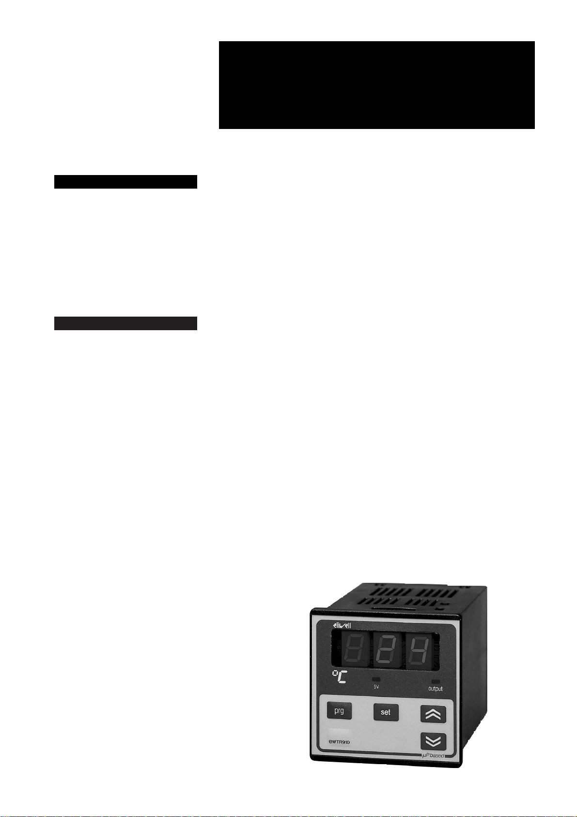
FRONT KEYPAD
SET: with this button the setpoint value
can be displayed. To change the value, this
button should be activated together with
the “UP” or “DOWN” button. In case parameter “dro” is set at “S”, the setpoint value
(SV) can be changed with the “UP” or
“DOWN” button only, while the process
temperature (PV) can be displayed with the
“SET” button.
UP: used to increase the setpoint value, as
well as the parameter when in programming. When held down for a few seconds,
the change rate accelerates.
DOWN: same functions except to decrease a value.
PRG: programming access button. To access programming, this button must be
pushed together with the concealed button located under “PRG” and “SET”, all at
the same time.
Led “OUTPUT”: status light of the output.
Led “SV” (Set Value): to indicate that the
Set Value (SV) is displayed. This occurs
when “SET” is pushed (parameter “dro”
set at “P”); it will stay on steady if parameter “dro” is set at “S”.
PARAMETER PROGRAMMING
Access the programming by pushing
“PRG”, then the concealed button below
“PRG” and “SET”, all at the same time.
The first parameter will appear and the
“OUTPUT” status light will blink throughout
the programming. Select the desired parameter with the “UP” and “DOWN” button.
With the “SET” button, the actual setting of
each parameter is displayed. To change a
parameter setting, push the “SET” plus the
“UP” (or “DOWN”).
To exit the programming, push “PRG” plus
the concealed button.
DESCRIPTION OF PARAMETERS
Any parameter which does not apply to a
particular instrument version is automatically removed from the programming
menu.
E.g.: a control for Thermocouple input will
not offer parameters “Lci” and “Hci”.
d1: differential setpoint 1.
The switching differential (hysteresis) can
be set with positive value (make on rise) or
with negative value (make on fall). See parameter “HC1”.
LS1: Lower Set 1.
This is the lower limit below which the user
cannot change the setpoint; normally set
at the lowest value recommended for the
sensor.
HS1: Higher Set 1.
Similar to “LS1”, however setting an upper
limit for the setpoint.
Pb: Proportional band.
Only for models with PID option. This value, expressed in degrees, determines the
band-width around the setpoint within
which the instrument provides proportion-
HOW IT IS MADE
• Dimensions: front 72x72 mm
(2.84x2.84"), depth 102 mm (4.00")
• Mounting: flush panel mount with
mounting bracket. Panel cut-out
67x67 mm (2.64x2.64")
• Connections: quick-disconnect
screw terminal blocks (2.5 mm
2
;
one wire each terminal only)
• Display: 12.5 mm LED (0.50")
• Output: one (1) SPDT relays 8(3)A
250V AC, or one (1) “static”
(switched) output 0/12 Vdc 40 mA
• Programmable analog output (optional): 4…20 mA or 0…5 V, depending on model
• Auxiliary output: 12 Vdc/60 mA
(for transducer power supply, e.g.
temperature sensor, etc.; ground
goes to terminal 10)
• Inputs (depending on model):
PTC / RTD (Ni100, Pt100) /
TC (J, K) / 4…20 mA (Ri = 41 Ω) for
EWTR 910, EWHS 28/31 for
EWHR 910 and EWPA 007/030 for
EWPR 910
• Resolution: 1 °C (°F) or 0,1 °C (°F).
The right-most digit can also be
set to read-out in 0 or 5 only, or in
all 10 digits
• Accuracy: better than 0.5% of full
scale
• Power supply (depending on model): 220, 110, 24 Vac, 50/60 Hz; 12
Vac/dc
WHAT IT IS
The EWTR 910 is a new series of
micro-processor based and fully
programmable process controllers
for single setpoint applications; the
output provides ON-OFF or PID
control. Three different versions of
this controller are available: EWTR
910 for Temperature, EWHR 910 for
Relative humidity and EWPR 910 for
Pressure control.
EWTR/HR/PR 910
rel. 12/96 ing
controllers one output 72x72
Page 2

2EWTR/HR/PR 910 12/96 ing
al control. See also “PROPORTIONAL
CONTROL”.
It: Integral time, expressed in seconds.
Only for models with PID option. The higher this setting, the “smoother” the integral
action. A setting of “0” completely eliminates the integral function and changes
the controller from PID to PD (output 1).
See also “PROPORTIONAL CONTROL”.
dt: derivative time, also expressed in seconds.
Only for models with PID option. The effect
of the derivative action is in direct proportion to this time setting. See also “PROPORTIONAL CONTROL”.
Sr: Sampling rate, in seconds.
Only for models with PID option. Time between two successive read-outs, for the
computation of the derivative. A low setting increases the response time, but also
the sensitivity to noise. Recommended
setting is from 1 to 3.
rSt: manual reSet.
Only for models with PID option. This allows the proportional band to be moved
up or down. This parameter is expressed
in degrees and must be set at a value opposite and corresponding to the noticed
error.
Ar: Anti-reset wind-up band.
Only for models with PID option. This is the
half-band (on either side of the setpoint) in
which the integral action takes place. The
higher this setting, the stronger the integral
action. Recommended initial setting: half
of the value of parameter “Pb”.
Ct: Cycle time (in seconds).
Only for models with PID option. This is the
total time of one ON+OFF cycle of the relay during the proportional action. See
“PROPORTIONAL CONTROL”.
od: output delay.
This provides a delay selection for the outputs in applications where noise may
cause brief erroneous signals from the
sensor to the controller. Factory set at “0”.
Lci: Lower current input.
Read-out corresponding to the “low end
scale” input signal of 4 mA; only for models with current input.
Hci: Higher current input.
Read-out corresponding to the “high end
scale” of 20 mA; only for models with current input.
LAO: Low Analog Output.
Low end of scale setting of analog output
(only for models with this option; see parameter “AOF”).
HAO: High Analog Output.
High end of scale setting of analog output
(only for models with this option; see parameter “AOF”).
CAL: CALibration.
This offers an adjustment up or down of
the read-out, if needed.
Factory set at “0”.
PSE: Probe SElection.
Input type (for RTD or Thermocouples
only).
RTD models: Ni = Ni100; Pt = Pt100.
T/C models: FE = TcJ; Cr = TcK.
AOF: Analog Output Function.
Analog output function (only for models
with this option; see parameters “LAO”
and “HAO”).
ro (read-out) = proportional to the system
temperature, within the read-out values
specified by parameters “LAO” and
“HAO”.
Er (Error) = proportional to temperature deviation from Setpoint, within the values
specified by parameters “LAO” and
“HAO”.
HC1: Heating / Cooling output 1.
Relay switch function output 1.
H = Heating (humidification; reverse action);
C = Cooling (dehumidification; direct action).
rP1: relay Protection 1.
Determines the status of the relay in case
of sensor defect. Factory set at “ro”.
ro = relay open; rc = relay closed
LF1: Led Function 1.
Determines whether the status light is ON
or OFF in relation to output 1.
di = direct = light ON when output 1 is energized;
in = reverse = light OFF when output 1 is
energized.
dP: decimal Point.
Choose whether the resolution is required
with or without decimal point.
oF = without decimal point;
on = with decimal point.
NOTES: (a) the decimal point of models
with current or voltage input is shifted: the
actual value of parameters “Lci” and “Hci”
must be multiplied by 10; (b) on all versions, if a unit is changed from without
decimal point to with decimal point, all parameter values expressed in degrees will
automatically be divided by 10, including
the setpoint !! (c) the decimal point selection is not available on models for thermocouple input.
dro: display read-out.
Display read-out reversal.
P (Process value) = system temperature
display.
S (Setpoint value) = setpoint temp. display.
AOS: Analog Output Security (only for
models with this optional analog output).
Sensor protection analog output.
Ao (Analog output on) = analog output ON
(100%) in case of sensor defect;
AF (Analog output oFf) = analog output
OFF (0%) in case of sensor defect.
hdd: half digit display.
The right-most digit can be set to read-out
DEFAULT SETTINGS - STANDARD MODELS
Parameter
d1
LS1
HS1
Pb*
It*
dt*
Sr*
rSt*
Ar*
Ct*
od
Lci
Hci
LAO**
HAO**
CAL
PSE
AOF**
HC1
rP1
LF1
dP
dro
AOS**
hdd
tAb
* Parameters visible only for special models with proportional operation (PID).
** Parameters visible only for special models with analog output.
Description
differential set 1
Lower Set limit 1
Higher Set limit 1
Proportional band
Integral time
derivative time
Sampling rate
manual reSet
Anti reset
Cycle time
output delay
Low current input
High current input
Low Analog Output
High Analog Output
CALibration
Probe SElection
Analog Output Function
Heating / Cooling out 1
relay Protection 1
Led Function 1
decimal Point
display read-out
Analog Output Security
half digit display
tAble of parameters
Range
min / max
min / max
min / max
0.1 (1) / max
0 / 999
0 / 999
1 / 10
min / max
0 / max
1 / 500
min / max
min / max
min / max
min / max
min / max
min / max
Ni / Pt / Fe / Cr
ro / Er
H / C
ro / rc
di / in
on / oF
S / P
Ao / AF
n / y
/
Unit
various
various
various
various
seconds
seconds
seconds
various
various
seconds
seconds
various
various
various
various
various
/
flag
flag
flag
flag
flag
flag
flag
flag
/
Default
1 (C) / –1 (H)
min
max
100
500
30
1
0
100
30
0
min
max
min
max
0
/
ro
/
ro
di
oF
P
AF
n
/
Page 3

3 EWTR/HR/PR 910 12/96 ing
in 0 or 5 only, or in all 10 digits.
hdd = n : e.g. 070, 071, 072 etc. (if without decimal point) or 70.0, 70.1, 70.2 etc.
(if with decimal point);
hdd = y : e.g. 070, 075, 080, etc. (if without decimal point) or 70.0, 70.5, 71,0, etc.
(if with decimal point). Useful when measuring values varying rapidly (e.g. %R.H.).
tAb: tAble of parameters.
This shows the configuration of the parameters as set in the factory; can not be
modified (for factory identification and diagnostic purposes only).
PROPORTIONAL CONTROL
In the event that the factory set parameter
values in a PID temperature controller do
not give optimum results, the following
steps may be followed to enhance the op-
eration for each specific application:
» select a value for Setpoint which will keep
the temperature swing within acceptable
limits, for example 10% below the normal
operating temperature;
» set the switching differential (“d1”) at 3%
of the setpoint temperature;
» start the system and wait for the temperature swings to become constant;
» check the process temperature (use a
data recorder if possible) at regular intervals; determine the time between two successive temperature peaks (Tu) as well as
the total temperature swing (dT).
Parameters “Pb”, “It”, “dt” and “Ct” can
now be calculated as follows:
Pb = 2xdT; It = Tu/2; dt = Tu/8; Ct = Tu/20.
Additional fine tuning of the above parameters may be tried, keeping in mind how-
ever the following:
- the “Proportional action” activates the
output in direct proportion to the shift in
stable system temperature;
- the “Derivative action” effects the output
depending on the speed of temperature
change;
- the “Integral action” activates the output
in proportion to the continuous integral calculation of the deviation values.
As a result:
a) an increase in the proportional band
width reduces the temperature swing, but
increases the shift in stable system temperature;
b) an excessive reduction of the proportional band width reduces deviation, but
will also make the system less stable;
c) an increase in the derivative time reduces temperature swings when the system has become stable, but may cause
wider temperature swings and increased
deviation from setpoint;
d) an increase in the integral time reduces
the deviation between setpoint and system
value when system has become stable;
e) a weak integral action always has a temperature deviation which, in general, can
be eliminated by reducing the proportional
band width and by increasing first of all the
derivative action, then the integral action.
INSTALLATION
The instrument is designed for flush panel
mounting; the required panel cut-out is
67x67 mm (2.64x2.64"). Insert the instrument from the front and tighten from the
rear with the two mounting brackets provided.
The ambient temperature around the instrument should be kept between –5 and
65 °C (23 and 149 °F). Select a location
which will not be subject to high humidity
or condensation and allow some ventilation to provide cooling to the instrument.
ELECTRICAL WIRING
Two quick-disconnect terminals are provided for easy and convenient wiring, even
before the instrument is actually installed.
Make sure that the power supply corresponds with the rating shown on the instrument; the power supply must be kept
within plus or minus 15% of the nameplate
voltage.
Separate the wiring of the input signals
from those of the power supply and
switched output wiring.
The relay output contacts are voltage free
and independent ; do not exceed the resistive rating of 8 Amp at 250 Vac. For larger loads, please use an external contactor
or relay.
ERROR ANNOUNCIATION
Any sensor input defect will be displayed
as follows: “---” in case of shorted sensor;
“EEE” in case of sensor break, or sensor
absence.
The “EEE” error message also appears in
load
11
12
13
14
15
16
17
18
EWTR 910
PTC
Pt100 / Ni100
3 wires
Pt100 / Ni100
2 wires
4…20 mA input
TcJ / TcK
+
–
analog
output
12 Vdc output
5
6
7
8
9
10
–
+
+
gnd
input
POWER SUPPLY
108 9 108 9 108 9
108 9108 9
CONNECTIONS
7 8 9
12 Vdc output
4…20 mA input
EWHS 28
EWHS 31
7 8 9
10
load
11
12
13
14
15
16
17
18
EWHR 910
POWER SUPPLY
analog
output
12 Vdc output
5
6
7
8
9
10
+
+
gnd
input
red
7 8 9
10
white
brown
blue
brown
–
7 8 9
12 Vdc output
4…20 mA input
EWPA 007
EWPA 030
7 8 9
10
load
11
12
13
14
15
16
17
18
EWPR 910
analog
output
12 Vdc output
5
6
7
8
9
10
–
+
+
gnd
input
brown
white
POWER SUPPLY
Page 4

the event of ovverrange or underrange of
the system temperature.
It is recommended to doublecheck the
sensor wiring before diagnosing a probe
as defective.
TECHNICAL DATA
Housing: black ABS plastic, autoestinguish.
Dimensions: front 72x72 mm
(2.84x2.84"), depth 102 mm (4.00").
Mounting: flush panel mount with mounting bracket. Panel cut-out 67x67 mm
(2.64x2.64").
Connections: quick-disconnect screw
terminal blocks (2.5 mm
2
; one wire each
terminal only).
Display: 12.5 mm LED (0.50").
Push buttons: located on front panel.
Data storage: non-volatile EEPROM
memory.
Operating temperature: –5…65 °C;
(23…149 °F).
Storage temperature: –30…75 °C;
(–22…167 °F).
Output: one (1) SPDT relay 8(3)A 250V
AC, or one (1) “static” (switched) output
0/12 Vdc 40 mA.
Programmable analog output(optional):
4…20 mA or 0…5 V, depending on model.
Auxiliary output: 12 Vdc/60 mA (for
transducer power supply).
Inputs(depending on model): PTC / RTD
(Ni100, Pt100) / TC (J, K) / 4…20 mA
(Ri=41 Ω) for EWTR 910, EWHS 28/31 for
EWHR 910 and EWPA 007/030 for EWPR
910.
Resolution: 1 °C (°F) or 0.1 °C (°F). The
right-most digit can also be set to read-out
in 0 or 5 only, or in all 10 digits.
Accuracy: better than 0.5% of full scale.
Power supply(depending on model):
12Vac/dc ±15%; 220, 110, 24 Vac ±10%,
50/60 Hz.
Eliwell
via dell’Artigianato, 65
Zona Industriale
32010 Pieve d’Alpago (BL)
Italy
Telephone +39 (0)437 986111
Facsimile +39 (0)437 989066
4EWTR/HR/PR 910 12/96 ing
 Loading...