

Page 1
Frequency Inverter
Convertidor de Frecuencia
Convertitore di Frequenza
Frequenzumrichter
Variateur de Vitesse
EWCFW-08
User's Manual
Manual del Usuario
Manuale dell´utente
Bedienungsanleitung
Manuel d'utilisation
Page 2

Page 3

ATTENTION!
Itisveryimportanttocheckif the inverter softwareversion is the sameas
indicatedabove.
¡
ATENCIÓN!
Es muy importante conferir si la versión de softwaredel Convertidor es igual a la
indicada arriba.
ATTENZIONE!
E 'molto importante verificare se la versione software del drive è quella sopra
indicato.
ACHTUNG!!
Bitteüberprüfen Sie,ob die SoftwareversiondesUmrichtersmit der Versionder
Betriebsan-leitungübereinstimmt.
ATTENTION!
Ilesttrès important de vérifier sila version logicielle du variateur est lamême
qu’indiquéeprécédemment.
Series:CFW-08
10000900189/02
E-S-I-G-F
FREQUENCY INVERTER MANUAL
MANUAL DEL CONVERTIDOR
DE FRECUENCIA
MANUALE DEL CONVERTITORE DI
FREQUENZA
BENIENUNGSANLEITUNG
FREQUENZUMRICHTERCFW-08
VARIATEUR DE VITESSE MANUEL
FREQUENCY INVERTER MANUAL
MANUAL DEL CONVERTIDOR
DE FRECUENCIA
MANUALE DEL CONVERTITORE DI
FREQUENZA
BENIENUNGSANLEITUNG
FREQUENZUMRICHTER CFW-08
VARIATEUR DE VITESSE MANUEL
Page 4

4
CONTENTS / ÍNDICE / SOMMARIO / INHALTSVERZEICHNIS / RÉSUMÉ
ENGLISH .......................................................................................................
Quick Parameter Reference, Fault and Status Messages
CHAPTER 1 - Safety Notices
CHAPTER 2 - General Information
CHAPTER 3 - Installation and Connection
CHAPTER 4 - Keypad (HMI) Operation
CHAPTER 5 - Start-up
CHAPTER 6 - Diagnostics and Troubleshooting
CHAPTER 7 - TechnicalSpecifications
ESPAÑOL ......................................................................................................
CAPÍTULO 1 -Instrucciones de Seguridad
CAPÍTULO 2 - Informaciones Generales
CAPÍTULO 3 - Instalación y Conexión
CAPÍTULO 4 - Uso de la HMI
CAPÍTULO 5 - Energización/Puesta en Marcha
CAPÍTULO 6 - Solución y Prevención de Fallas
ITALIANO ......................................................................................................
Parametridi Riferimento, Messaggi D’allarme e Stati
CAPITOLO 1 - Istruzioni per la Sicurezza
CAPITOLO 2 - Informazioni Generali
CAPITOLO 3 - Installazione
CAPITOLO 4 - Start
CAPITOLO 5 - Interfaccia HMI
CAPITOLO 6 - Diagnostica e guasti
CAPITOLO7-Specifichetecniche
GERMANY.....................................................................................................
KAPITEL 1 - Sicherheitshinweise
KAPITEL 2 - Allgemeine Informationen
KAPITEL 3 - Installation
KAPITEL 4 - Funktionen der Bedieneinheit (HMI)
KAPITEL 5 - Inbetriebnahme
FRANÇAIS.....................................................................................................
CHAPITRE 1 - Instructions de sécurité
CHAPITRE 2 - Informations generales
CHAPITRE 3 - Installation
CHAPITRE 4 - Demarrage
CHAPITRE 5 - Fonctionnement de l'interface HMI
Page 5

FREQUENCY INVERTER MANUAL
Quick Parameter Reference, Fault and Status Messages
CHAPTER 1
Safety Notices
1.1SafetyNoticesintheManual................................................. 16
1.2SafetyNoticesonThe Product.............................................. 16
1.3PreliminaryRecommendations............................................. 16
CHAPTER 2
General Information
2.1About this Manual .................................................................. 18
2.2Software Version................................................................... 18
2.3AbouttheCFW-08 ................................................................ 19
2.4CFW-08 Identification ........................................................... 23
2.5ReceivingandStoring ........................................................... 26
CHAPTER 3
Installation and Connection
3.1MechanicalInstallation .......................................................... 27
3.2Electrical Installation.............................................................. 32
3.3 European EMCDirective - Requirements
forConformingInstallations.................................................. 50
CHAPTER 4
Keypad (HMI) Operation
4.1Keypad(HMI)Description..................................................... 66
4.2Use of theKeypadHMI ......................................................... 67
CHAPTER 5
Start-up
5.1 Pre-Power Checks................................................................ 73
5.2Initial Power-up...................................................................... 73
5.3Start-up... ............................................................................. 74
CHAPTER 6
Diagnosticsand Troubleshooting
6.1Faults and Possible Causes ................................................. 76
6.2Troubleshooting..................................................................... 79
CHAPTER 7
TechnicalSpecifications
7.1 Power Data ........................................................................... 81
7.2Electronics/GeneralData ...................................................... 85
English
Page 6

Page 7

7
CFW-08 - QUICK PARAMETER REFERENCE
Software: V5.2X
Application:
Model:
SerialNumber:
Responsible:
Date: / / .
I.Parameters
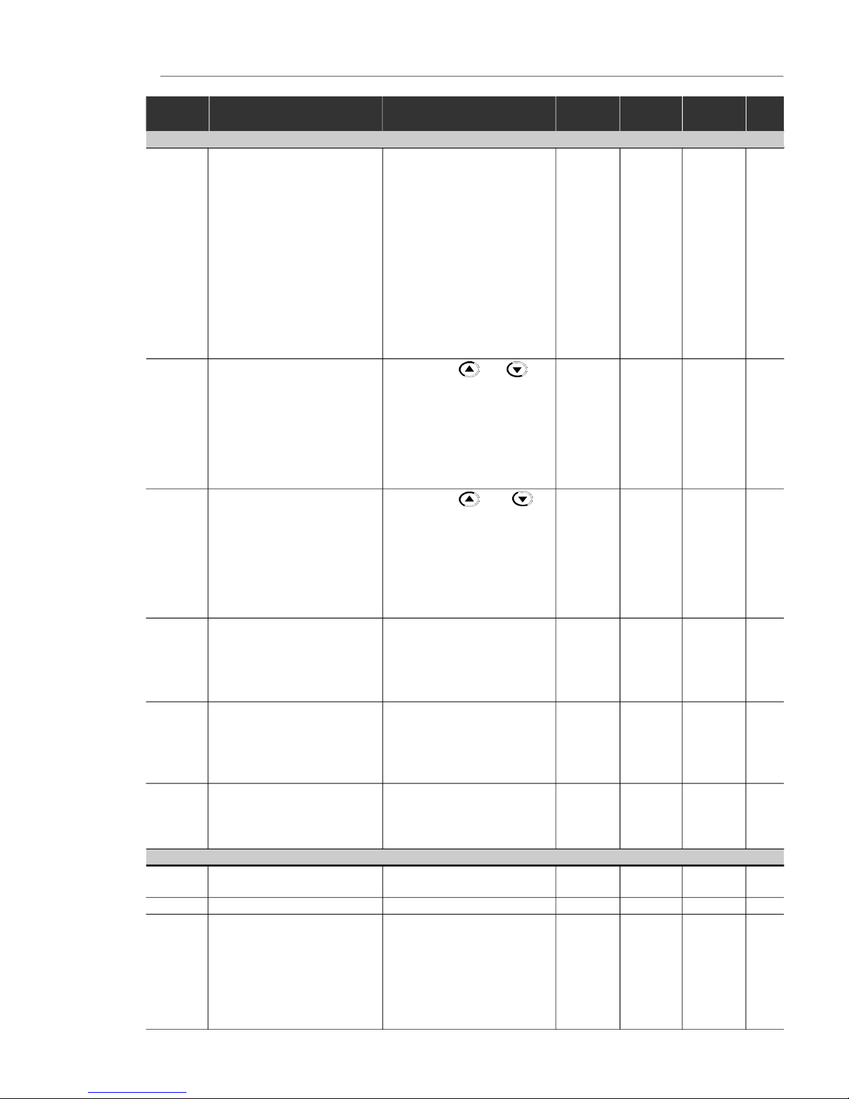
QUICK PARAMETER REFERENCE, FAULT AND STATUS MESSAGES
Parameter Function Adjustable Range
Factory
Unit
User
Page
Setting Setting
P000 ParameterAccess 0 to 4 = Read 0 -
5 = Alteration
6 to 999 = Read
READONLY PARAMETERS-P002 to P099
P002 FrequencyProportionalValue 0 to 6553 - -
(P208xP005)
P003 MotorOutput Current 0to 1.5xI
nom
- A
P004 DCLink Voltage 0 to 862 - V
P005 Motor Output Frequency 0.00 to 300.0 - Hz
P007 MotorOutputVoltage 0 to 600 - V
P008 HeatsinkTemperature 25 to 110 - °C
P009
(1)
MotorTorque 0.0 to 150.0 - %
P014 Last Fault 00 to 41 - -
P023 SoftwareVersion x . y z - -
P040 PID ProcessVariable 0 to 6553 - -
(Value % x P528)
REGULATION PARAMETERS-P100 to P199
Ramps
P100 AccelerationTime 0.1 to 999 5.0 s
P101 DecelerationTime 0.1 to 999 10.0 s
P102 Ramp 2AccelerationTime 0.1 to 999 5.0 s
P103 Ramp2DecelerationTime 0.1 to 999 10.0 s
P104 S Ramp 0= Inactive 0 -
1 = 50 %
2 = 100 %
Frequency Reference
P120 DigitalReferenceBackup 0= Inactive 1 -
1 = Active
2 = Backup by P121
P121 KeypadReference P133 to P134 3.00 Hz
P122 JOGSpeedReference 0.00 to P134 5.00 Hz
P124 MultispeedReference1 P133 to P134 3.00 Hz
P125 MultispeedReference2 P133 to P134 10.00 Hz
P126 MultispeedReference3 P133 to P134 20.00 Hz
P127 MultispeedReference4 P133 to P134 30.00 Hz
P128 MultispeedReference5 P133 to P134 40.00 Hz
P129 MultispeedReference6 P133 to P134 50.00 Hz
P130 MultispeedReference7 P133 to P134 60.00 Hz
P131 MultispeedReference8 P133 to P134 66.00 Hz
Page 8

8
CFW-08 - QUICK PARAMETER REFERENCE
Parameter Function
Adjustable Range
Factory
Unit
User
Page
Setting Setting
(*) The factory default of parameter P136 depends on the inverter model as follows:
- models 1.6-2.6-4.0-7.0 A/200-240 V and 1.0-1.6-2.6-4.0 A/380-480 V: P136 = 5.0 %;
- models 7.3-10-16 A/200-240 V and 2.7-4.3-6.5-10 A/380-480 V: P136 = 2.0 %;
- models 22-28-33 A/200-240 V and 13-16-24-30 A/380-480 V: P136 = 1.0 %.
Speed Limits
P133 Minimum Frequency (F
min
) 0.00 to P134 3.00 Hz
P134 MaximumFrequency(F
max
) P133 to 300.0 66.00 Hz
V/F Control
P136
(2) (*)
ManualTorqueBoost 0.0 to 30.0 5.0 or %
(IxRCompensation) 2.0 or
1.0
(*)
P137
(2)
AutomaticTorqueBoost 0.00 to 1.00 0.00 (AutomaticIxRCompensation)
P138
(2)
SlipCompensation 0.0 to 10.0 0.0 %
P142
(2) (3)
Maximum Output Voltage 0 to 100 100 %
P145
(2) (3)
FieldWeakening P133 to P134 50.00Hzor Hz
Frequency(F
nom
) 60.00 Hz
depending
on the
market
DC Link Voltage Regulation
P151 DCLink VoltageRegulation 200 V models: 325 to 410 380 V
Level 400 V models: 564 to 820 780
Overload Current
P156 MotorOverloadCurrent 0.2xI
nom
to 1.3xI
nom
1.2xP401 A
Current Limitation
P169 MaximumOutput Current 0.2xI
nom
to 2.0xI
nom
1.5xP295 A
Flux Control
P178
(1)
Rated Flux 50.0 to 150 100 %
CONFIGURATION PARAMETERS - P200 to P398
Generic Parameters
P202
(3)
ControlMode 0 = Linear V/F Control 0 -
(Scalar)
1 = Quadratic V/F Control
(Scalar)
2 = SensorlessVectorControl
P203
(3)
SpecialFunction Selection 0 = No function 0 -
1 = PID Regulator
P204
(3)
Load Factory Setting 0 to 4 = No Function 0 -
5 = Loads Factory Default
P205 DisplayDefault Selection 0 = P005 2 -
1 = P003
2 = P002
3 = P007
4, 5 = Not Used
6 = P040
P206 Auto-ResetTime 0 to 255 0 s
P208 ReferenceScaleFactor 0.00 to 99.9 1.00 -
P212 Frequencyto Enable the Sleep 0.00 to P134 0.00 Hz
Mode
P213 Time Delayto Activate the 0.1 to 999 2.0 s
SleepMode
P215
(3) (4)
Keypad Copy Function 0 = Not Used 0 -
1 = Copy (inverter keypad)
2= Paste(keypad inverter)
P219
(3)
SwitchingFrequency 0.00 to 25.00 6.00 Hz
ReductionPoint
Page 9
9
CFW-08 - QUICK PARAMETER REFERENCE
Parameter Function
Adjustable Range
Factory
Unit
User
Page
Setting Setting
(**) Only available on the control board A2 (refer to item 2.4). For programming instructions, please, refer to the parameter P235 detailed
description.
Local/Remote Definition
P220
(3)
Local/Remote 0 = Always Local 2 Selection Source 1 = Always Remote
2 = HMI-CFW08-P or
HMI-CFW08-RPKeypad
(default:local)
3 = HMI-CFW08-P or
HMI-CFW08-RPKeypad
(default:remote)
4 = DI2 to DI4
5= SerialorHMI-CFW08-RS
Keypad(default: local)
6= SerialorHMI-CFW08-RS
Keypad(default: remote)
P221
(3)
FrequencyLocalReference 0 = Keypad and 0 Selection 1 = AI1
2, 3 = AI2
4 = E.P.
5 = Serial
6 = Multispeed
7 = AddAI0
8 = Add AI
P222
(3)
FrequencyRemoteReference 0 = Keypad and 1 Selection 1 = AI1
2, 3 = AI2
4 = E.P.
5 = Serial
6 = Multispeed
7 = AddAI0
8 = Add AI
P229
(3)
LocalCommand Selection 0=HMI-CFW08-P or 0 -
HMI-CFW08-RPKeypad
1 = Terminals
2 = Serial or
HMI-CFW08-RSKeypad
P230
(3)
RemoteCommand Selection 0= HMI-CFW08-P or 1 -
HMI-CFW08-RPKeypad
1 = Terminals
2 = Serial or
HMI-CFW08-RSKeypad
P231
(3)
Forward/ReverseSelection 0 = Forward 2 -
- Local and Remote 1= Reverse
2 = Commands
3 = DIx
Analog Input (s)
P233 AnalogInputDeadZone 0= Inactive 1 -
1 = Active
P234 Analog InputAI1 Gain 0.00 to 9.99 1.00 -
P235
(3) (5)
Analog InputAI1 Function 0 = (0 to 10) V/(0 to 20) mA / 0 -
(-10 to +10) V
(**)
1 = (4 to 20) mA
2 = DI5 PNP
3 = DI5 NPN
4= DI5TTL
5 = PTC
Page 10

10
CFW-08 - QUICK PARAMETER REFERENCE
Parameter Function
Adjustable Range
Factory
Unit
User
Page
Setting Setting
P236 Analog InputAI1 Offset -999 to +999 0.0 %
P238
(6)
AnalogInputAI2Gain 0.00 to 9.99 1.00 -
P239
(3)(5)(6)
Analog InputAI2 Function 0 = (0 to 10) V/(0 to 20) mA/ 0 -
(-10 to +10) V
(**)
1 = (4 to 20) mA
2 = DI6 PNP
3 = DI6 NPN
4= DI6TTL
5 = PTC
P240
(6)
AnalogInputAI2Offset -999 to +999 0.0 %
P248 Analog Inputs Filter 0 to 200 10 ms
TimeConstant
Analog Output
P251
(6)
AnalogOutput 0 = Output Frequency (Fs) 0 AO Function 1 = Input Reference(Fe)
2 = Output Current (Is)
3, 5, 8 = Not Used
4 = Motor Torque
6 = Process Variable (PID)
7 = Active Current
9 = PID Setpoint
P252
(6)
Analog Output AO Gain 0.00 to 9.99 1.00 -
P253 Analog Output AO Signal 0 = (0 to 10) V/(0 to 20) mA 0 -
1 = (4 to 20) mA
Digital Inputs
P263
(3)
Digital Input DI1 Function 0 = No Function or General 0 -
Enable
1 to 7 and 10 to 12 =
GeneralEnable
8 = Forward Run
9 = Start/Stop
13 = FWD Run Using
Ramp2
14 = On
P264
(3)
Digital Input DI2 Function 0 =Forward/Reverse 0 -
1 = Local/Remote
2 to 6 and 9 to 12 = Not Used
7 = Multispeed (MS2)
8= Reverse
13 = REV Run - Ramp 2
14 = Off
P265
(3) (7)
Digital Input DI3 Function 0 = Forward/Reverse 10 -
1 = Local/Remote
2 = GeneralEnable
3 = JOG
4 = No External Fault
5 = Increase E.P.
6 = Ramp 2
7 = Multispeed (MS1)
8 = No Function or
Start/Stop
9 = Start/Stop
10 = Reset
(**) Only available on the control board A2 (refer to item 2.4). For programming instructions, please, refer to the parameter P235 detailed
description.
Page 11

11
CFW-08 - QUICK PARAMETER REFERENCE
Parameter Function
Adjustable Range
Factory
Unit
User
Page
Setting Setting
11, 12 = Not Used
13 = Flying Start Disable
14 = Multispeed (MS1)
UsingRamp 2
15 = Manual/Automatic (PID)
16 = Increase E.P. with
Ramp2
P266
(3)
Digital Input DI4 Function 0 = Forward/Reverse 8 -
1 = Local/Remote
2 = GeneralEnable
3 = JOG
4 = No External Fault
5 = Decrease E.P.
6 = Ramp 2
7 = Multispeed (MS0)
8 = Not Used or
Start/Stop
9 = Start/Stop
10 = Reset
11, 12,14 and 15 = Not Used
13 = Flying Start Disable
16 = Decrease E.P.with
Ramp2
P267
(3) (5)
Function of the Digital 0 = FWD/REV 11 InputDI5 (only displayed 1 = Local/Remote
when P235 = 2, 3 or 4) 2 = General Enable
3 = JOG
4 = No External Fault
5 = Increase E.P.
6 = Ramp 2
7 = Multispeed (MS2)
8 = No Functionor Start/Stop
9 = Start/Stop
10 = Reset
11 and 12 = Not Used
13 = Disables Flying Start
14 and 15 = Not Used
16 = Increase E.P. with
Ramp2
P268
(3) (5) (6)
Function of the Digital 0 = FWD/REV 11 InputDI6 (only displayed 1 = Local/Remote
when P239 = 2, 3 or 4) 2 = General Enable
3 = JOG
4 = No External Fault
5 = Decrease E.P.
6 = Ramp 2
7 = Not Used
8 = No Function or Start/Stop
9 = Start/Stop
10 = Reset
11 and 12 = Not Used
13 = Disables Flying Start
14 and 15 = Not Used
16 = Decrease E.P.with
Ramp2
Page 12

12
CFW-08 - QUICK PARAMETER REFERENCE
Parameter Function
Adjustable Range
Factory
Unit
User
Page
Setting Setting
(*) It is not possible to set P297 = 7 (15 kHz) in vector control mode (P202 = 2) or when the external serial keypad (HMI-CFW08-RS) is used.
According
to the
inverter
model
DigitalOutput(s)
P277
(3)
RelayOutput RL1 Function 0 = Fs > Fx 7 -
1 = Fe > Fx
2 = Fs = Fe
3 = Is>Ix
4 and 6 = Not Used
5 = Run
7 = No Fault
P279
(3) (6)
RelayOutput RL2 Function 0 = Fs > Fx 0 -
1 = Fe > Fx
2 = Fs = Fe
3 = Is > Ix
4 and 6 = Not Used
5 = Run
7 = No Fault
Fx and Ix
P288 Fx Frequency 0.00to P134 3.00 Hz
P290 IxCurrent 0to 1.5xI
nom
1.0xI
nom
A
Inverter Data
P295
(3)
RatedInverter 300 = 1.0 A Current(I
nom
) 301 = 1.6 A
302 = 2.6 A
303 = 2.7 A
304 = 4.0 A
305 = 4.3 A
306 = 6.5 A
307 = 7.0 A
308 = 7.3 A
309 = 10A
310 = 13A
311 = 16 A
P297
(3)
SwitchingFrequency 4 = 5.0 4 kHz
5 = 2.5
6 = 10
7 = 15
(*)
DC Braking
P300 DC BrakingTime 0.0 to 15.0 0.0 s
P301 DC Braking Start Frequency 0.00 to 15.00 1.00 Hz
P302 DC BrakingCurrent 0.0 to 130 0.0 %
Skip Frequencies
P303 Skip Frequency1 P133 to P134 20.00 Hz
P304 Skip Frequency2 P133 to P134 30.00 Hz
P306 Skip Band Range 0.00 to 25.00 0.00 Hz
Serial Communication Interface I
P308
(3)
InverterAddress 1 to 30 (Serial WBus) 1 -
1to 247 (Modbus-RTU)
Flying Start and Ride-Through
P310
(3)
FlyingStartandRide-Through 0= Inactive 0 -
1 = Flying Start
2 = Flying Start and
Ride-Through
3= Ride-Through
312 = 22A
313 = 24A
314 = 28A
315 = 30A
316 = 33A
Page 13

13
CFW-08 - QUICK PARAMETER REFERENCE
Parameter Function
Adjustable Range
Factory
Unit
User
Page
Setting Setting
P311 VoltageRamp 0.1 to 10.0 5.0 s
Serial Communication Interface II
P312
(3)
SerialInterfaceProtocol 0 = Serial Wbus 0 -
1 = Modbus-RTU 9600 bps
without parity
2 = Modbus-RTU 9600 bps
with odd parity
3 = Modbus-RTU 9600 bps
witheven parity
4 = Modbus-RTU 19200 bps
without parity
5 = Modbus-RTU 19200 bps
with odd parity
6 = Modbus-RTU 19200 bps
witheven parity
7 = Modbus-RTU 38400 bps
without parity
8 = Modbus-RTU 38400 bps
with odd parity
9 = Modbus-RTU 38400 bps
witheven parity
P313 SerialInterfaceWatchdog 0 = Disabling by ramp 2 -
Action 1= General disable
2 = Shows only E28
3 = Goes to local mode
P314 SerialInterfaceWatchdog 0.0 = Disables the function 0.0 s
Timeout 0.1to 99.9 = Setvalue
MOTORPARAMETERS- P399 toP499
Rated Parameters
P399
(1) (3)
Rated MotorEfficiency 50.0 to 99.9 %
P400
(1) (3)
RatedMotor Voltage 0 to 600 V
P401 RatedMotorCurrent 0.3xP295 to 1.3xP295 A
P402
(1)
RatedMotorSpeed 0 to 9999 rpm
P403
(1) (3)
Rated Motor Frequency 0.00 to P134 Hz
P404
(1) (3)
RatedMotorPower 0 = 0.16 HP / 0.12 kW -
1 = 0.25 HP / 0.18 kW
2 = 0.33 HP / 0.25 kW
3 = 0.50 HP / 0.37 kW
4 = 0.75 HP / 0.55 kW
5 = 1 HP / 0.75 kW
6 = 1.5 HP / 1.1 kW
7 = 2 HP / 1.5 kW
8 = 3 HP / 2.2 kW
9 = 4 HP / 3.0 kW
10 = 5 HP / 3.7 kW
11 = 5.5 HP / 4.0 kW
12 = 6 HP / 4.5 kW
13 = 7.5 HP / 5.5 kW
14 = 10 HP / 7.5 kW
15 = 12.5 HP / 9.2 kW
16 = 15 HP / 11.2 kW
17 = 20 HP / 15.0 kW
According
to the
inverter
model
(motor
matched
to the
inverter)
Page 14

14
CFW-08 - QUICK PARAMETER REFERENCE
According to
theinverter
model
According to
theinverter
Parameter Function
Adjustable Range
Factory
Unit
User
Page
Setting Setting
Notesfound on the Quick ParameterReference:
(1) This parameter is onlydisplayedin vector mode (P202 = 2).
(2) This parameter is only displayedin scalar mode P202 = 0 or 1.
(3) This parameter can bechangedonlywhen the inverter is disabled (stoppedmotor).
(4) This parameterisonlyavailablewithHMI-CFW08-RS.
(5) Theanaloginputvalueis representedbyzerowhenitisnotconnectedtoan externalsignal.
In order to use an analog input as a digital input with NPN logic (P235 or P239 = 3), it is
necessary to connect a 10 k resistor from terminal 7 to 6 (AI1) or 8 (AI2) of the control
terminalstrip.
(6) This parameteris onlyavailableinthe CFW-08Plus version.
(7) The parametervalue changes automaticallywhenP203 = 1.
P407
(3)
RatedMotorPower 0.50 to 0.99 Factor
Measured Parameters
P408
(1) (3)
RunSelf-Tuning 0 = No 0 -
1 = Yes
P409
(3)
Motor Stator Resistance 0.00 to 99.99
model
SPECIAL FUNCTION - P500 to P599
PID Regulator
P520 PIDProportionalGain 0.000 to 7.999 1.000 -
P521 PIDIntegralGain 0.000 to 9.999 1.000 -
P522 PIDDifferentialGain 0.000 to 9.999 0.000 -
P525 Setpoint (Via Keypad) of the 0.00 to 100.0 0.00 %
PIDRegulator
P526 Process Variable Filter 0.01 to 10.00 0.10 s
P527 PIDAction 0 = Direct 0 -
1= Reverse
P528 Process Variable 0.00 to 99.9 1.00 -
Scale Factor
P535 Wake up Band 0.00 to 100.00 1.00 %
P536 Automatic Setting of P525 0= Active 0 -
1= Inactive
Page 15

15
CFW-08 - QUICK PARAMETER REFERENCE
Display Description Page
E00 Outputovercurrent/short-circuit/outputgroundfault
E01 DC link overvoltage
E02 DC linkundervoltage
E04
Overtemperatureat the powerheatsink or in the
inverterinternalair
E05 Output overload(Ixt function)
E06 External fault
E08 CPU error(Watchdog)
E09 Program memoryerror(Checksum)
E10 Keypad copy function error
E14 Self-tuning routine (estimationof the motor
parameters)error
E22,E25,
Serialcommunicationerror
E26 and E27
E24 Programmingerror
E28 Serial interface Watchdog timeouterror
E31 Keypadconnectionfault(HMI-CFW08-RS)
E32 Motorovertemperature(external PTC)
E41 Self-diagnosisfault
II.FaultMessages
III.OtherMessages
Display Description
rdy Inverteris readyto be enabled
Sub
Powersupply voltage is too low for the inverter
operation(undervoltage)
dcbr Inverterin DC brakingmode
auto Inverterisrunningself-tuningroutine
copy
Keypadcopy function in progress (only available in
theHMI-CFW08-RS)- inverterto keypad
past
Keypadcopy function in progress (only available in
theHMI-CFW08-RS)- keypadto inverter
Srdy Inverter in the sleep rdy mode
Page 16
16
CHAPTER1
SAFETYNOTICES
This Manual contains necessaryinformation for the correct
useof the CFW-08frequencyinverter.
This Manual was developed for qualified personnel with
suitabletrainingandtechnicalqualificationtooperatethistype
ofequipment.
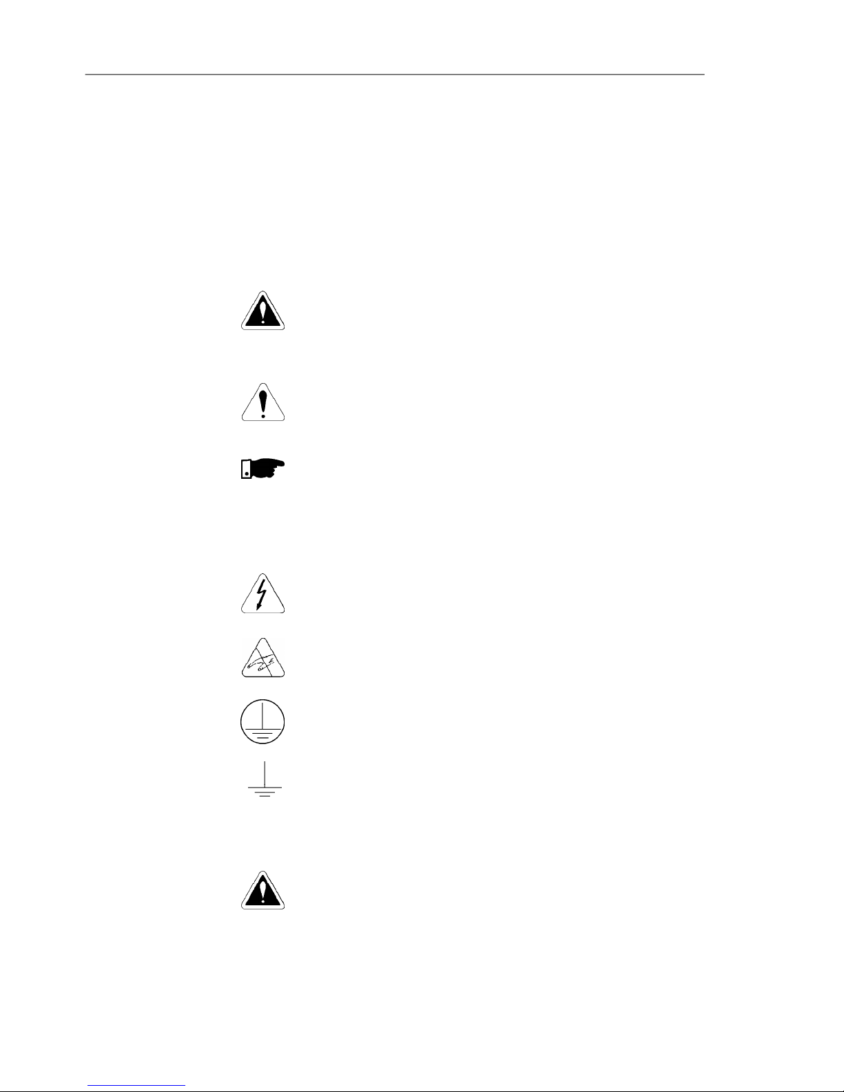
Thefollowingsafetynoticesareusedin thismanual:
DANGER!
Iftherecommended safetynoticesarenot strictlyobserved,it
canleadtoseriousorfatalinjuriesofpersonneland/ormaterial
damage.
ATTENTION!
Failureto observe the recommendedsafetyprocedurescan
lead to material damage.
NOTE!
This notice provides important information for the proper
understandingandoperationof theequipment.
Thefollowingsymbolsmaybeattachedtotheproduct,serving
assafetynotice:
High Voltages.
Componentssensitiveto electrostaticdischarge. Do not
touch them without proper grounding procedures.
Mandatory connection to ground protection (PE).
Shield connection to ground.
DANGER!
Only qualified personnel should plan or implement the
installation, start- up, operation and maintenance of this
equipment. Personnel must review entire Manual before
attemptingto install,operateortroubleshoottheCFW-08.
Thesepersonnel must followall safetyinstructionsincluded
inthismanualand/ordefinedbylocal regulations.
Failure to comply with these instructions may result in
personnelinjuryand/orequipmentdamage.
1.3 PRELIMINARY
RECOMMENDATIONS
1.2 SAFETYNOTICES
ONTHE PRODUCT
1.1 SAFETYNOTICESIN
THEMANUAL
Page 17
17
CHAPTER 1 - SAFETY NOTICES
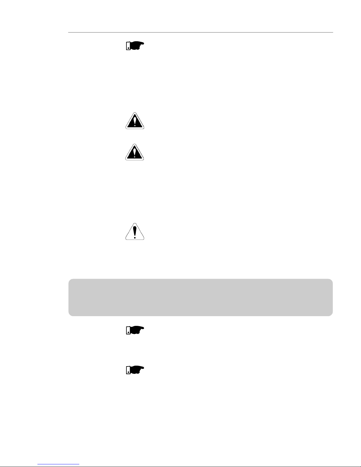
NOTE!
Inthis manual,qualifiedpersonnelare definedas peoplethatare
trainedto:
1. Install,ground,powerup and operatetheCFW-08according
tothis manual andthe localrequiredsafetyprocedures;
2. Useofsafetyequipment accordingtothelocal regulations;
3. Administer FirstAid.
DANGER!
Theinvertercontrol circuit (ECC3, DSP) and theHMI-CFW08-P
arehighvoltagecircuitsandare notgrounded.
DANGER!
Always disconnect the supply voltage before touching any
electricalcomponentinside theinverter.
Many components are charged with high voltage and/or in
movement (fans), even aftertheincomingAC power supply has
beendisconnectedorswitchedOFF. Waitatleast10 minutesfor
thetotal discharge of the powercapacitors.
Alwaysconnecttheframeoftheequipmenttotheground(PE)at
thesuitableconnectionpoint.
ATTENTION!
All electronic boards have components that are sensitive to
electrostatic discharges. Never touch any of the electrical
components or connectors without following proper grounding
procedures. If necessary to do so, touch the properlygrounded
metallicframe or use a suitablegroundstrap.
NOTE!
Inverterscaninterferewithotherelectronicequipment.Inorderto
reduce this interference, adopt the measures recommended in
chapter3 - Installationand Connection.
NOTE!
ReadthisentiremanualbeforeinstallingoroperatingtheCFW-08.
Do not apply high voltage (high pot) test on the inverter!
If this test is necessary, contact Eliwell.
Page 18

18
Thischapterdefinesthecontentsandpurposesof thismanual and describes the main characteristics of the CFW-08
frequency inverter. Identification, receiving inspections and
storagerequirementsarealso provided.
Thismanual is divided into 7 chapters,providing information
to the user on how receive, install, start-up and operate the
CFW-08.
Chapter 1 - Safetynotices.
Chapter 2 - Generalinformationand receivingtheCFW-08.
Chapter 3 - RFIfilters, mechanical and electricalinstallation
(powerandcontrolcircuit).
Chapter 4 - Using the keypad (Human Machine Interface -
HMI).
Chapter 5 - Start-upandstepstofollow.
Chapter 6 - Solving problems, cleaning instructions and
preventivemaintenance.
Chapter 7 - CFW-08ratings,tablesandtechnicalinformation.
This manual provides information for the correct use of the
CFW-08. This frequency inverter is very flexible and allows
the operation in many different modes as described in this
manual.
AstheCFW-08canbeappliedinseveralways,itisimpossible
todescribeherealloftheapplicationpossibilities.Eliwelldoes
not accept any responsibility when the CFW-08 is not used
accordingto thismanual.
Nopartofthismanualmaybereproducedinanyform,without
thewrittenpermission of Eliwell.
It is important to note the software version installed in the
CFW-08, since it defines the functionsandtheprogramming
parameters of the inverter.
This manual refers to the software version indicated on the
insidecover.Forexample,theversion3.0Xappliestoversions
3.00 to 3.09, where “X” is a variable that will change due to
minor software revisions.The operation of the CFW-08 with
these software revisions are still covered by this version of
themanual.
Thesoftwareversion can be readin the parameterP023.
GENERALINFORMATION
2.1 ABOUTTHIS
MANUAL
2.2 SOFTWARE
VERSION
CHAPTER2
Page 19

19
CHAPTER 2 - GENERAL INFORMATION
2.3 ABOUTTHE CFW-08
TheCFW-08frequencyinverterprovidestwocontroloptions:
vector control (VVC: voltage vector control) or V/F (scalar);
bothtypes of controlcan be setaccordingtothe application.
Inthevectorcontrolmode,themotorperformanceisoptimized
relatingto torqueand speed regulation.
The"Self-Tuning"function,availableinvectorcontrol,permits
the automatic setting of the inverter parameter from the
identification(alsoautomatic)oftheparametersof themotor
connectedat the inverteroutput.
The V/F (scalar) mode is recommended for simpler
applicationssuchaspumpandfandrives.Inthesecasesone
can reduce the motor and inverter losses by using the
"QuadraticV/F" option, thatresultsin energysaving.
TheV/Fmodeisalsousedwhenmorethanonemotorshould
be driven simultaneously by one inverter (multimotor
application).
For power ratings and further technical information, refer to
Chapter7.
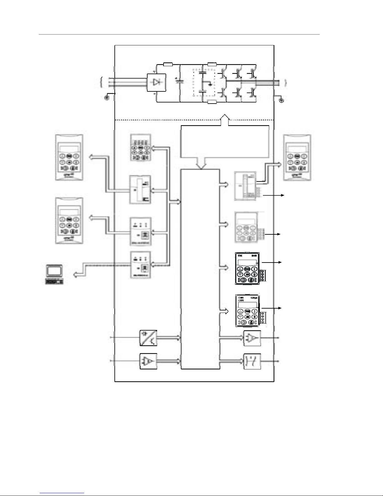
The block diagram below gives a general overview of the
CFW-08.
Page 20
20
CHAPTER 2 - GENERAL INFORMATION
Figure 2.1 - Block diagram for the models:
1.6-2.6-4.0-7.0A/200-240 V and1.0-1.6-2.6-4.0A/380-480V
Power
Supply
R
S
T
PE
HMI-CFW08-RS
PC-Software
SuperDrive
Analog
Inputs
(AI1andAI2)
Digital
Inputs
(DI1toDI4)
Interface
RS-232KCS-CFW08
Interface
MIS-CFW08-RS
or
HMI-CFW08-P
POWER
CONTROL
POWER SUPPLIESAND
CONTROL/ POWER
INTERFACES
"ECC3"
CONTROL
BOARD
WITHDSP
Motor
U
V
W
Rsh2
Rsh1
NTC
PE
RFIFilter
HMI-CFW08-RP
Interface
MIP-CFW08-RP
or
or
Analog
Output
(AO)
Relay
Output
(RL1and RL2)
CANopen
or
DeviceNet
KRS-485
KFB-COor KFB-DN
RS-485
24 V Power
Supply
24 V Power
Supply
HMI-CFW08-RP
KDC-24VR-CFW08
KDC-24V-CFW08
Page 21
21
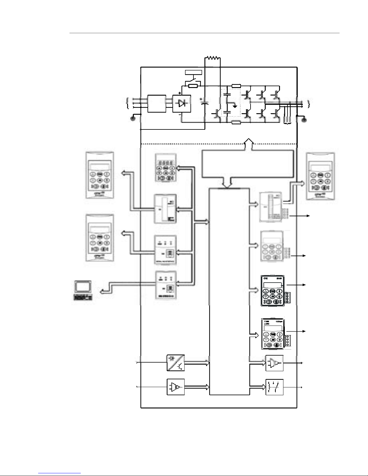
CHAPTER 2 - GENERAL INFORMATION
Figure 2.2 - Block diagram for the models:
7.3-10-16-22A/200-240V and 2.7-4.3-6.5-10-13-16A/380-480V
Note: models 16 A and 22 A/200-240 V are not fitted with optional RFI filter.
Redede
Alimentação
R
S
T
RFI
Suppressor
Filter
(optional)
HMI-CFW08-RS
PC-Software
SuperDrive
Analog
Inputs
(AI1andAI2)
Digital
Inputs
(DI1toDI4)
Interface
RS-232KCS-CFW08
Interface
MIS-CFW08-RS
HMI-CFW08-P
POWER
CONTROL
POWER SUPPLIESANDCONTROL
/POWER INTERFACES
"ECC3"
CONTROL
BOARD
WITHDSP
Motor
U
V
W
Rsh2
Rsh1
RPC
Pré-Carga
Braking Resistor
(ExternalandOptional)
BR
+UD
PE
-UD
Voltage
Feedback
PE
or
or
RFIFilter
or
Interface
MIP-CFW08-RP
HMI-CFW08-RP
Analog
Output
(AO)
Relay
Output
(RL1and RL2)
CANopen
or
DeviceNet
KRS-485
KFB-COor KFB-DN
RS-485
24 V Power
Supply
24 V Power
Supply
HMI-CFW08-RP
KDC-24VR-CFW08
KDC-24V-CFW08
Page 22
22
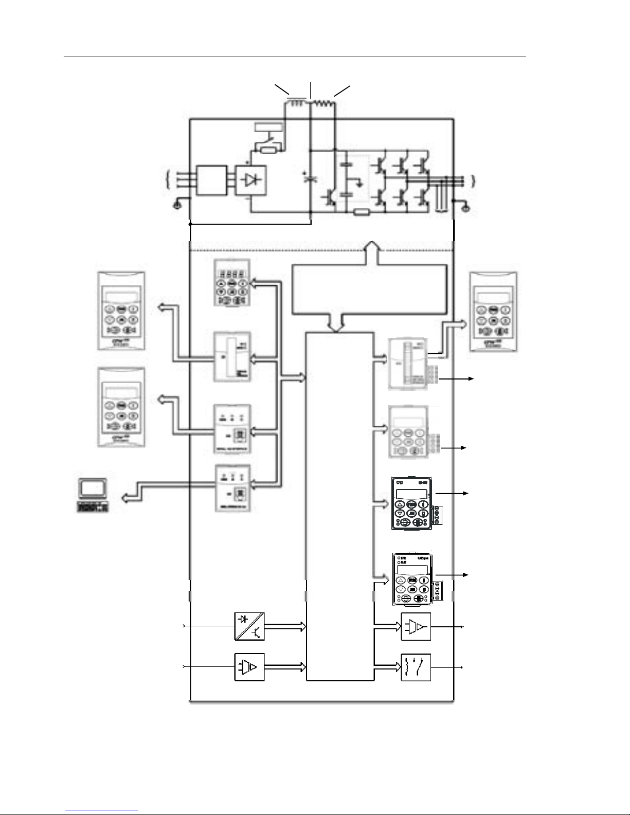
CHAPTER 2 - GENERAL INFORMATION
Figure 2.3 - Block diagram for the models:
28-33A/200-240 V and 24-30 A/380-480V
Note: models 28 A and 33 A/200-240 V are not fitted with optional RFI filter.
Power
Supply
R
S
T
RFI
Suppressor
Filter
(optional)
HMI-CFW08-RS
PC-Software
SuperDrive
Analog
Inputs
(AI1andAI2)
Digital
Inputs
(DI1toDI4)
Interface
RS-232KCS-CFW08
Interface
MIS-CFW08-RS
HMI-CFW08-P
POWER
CONTROL
POWER SUPPLIESAND
CONTROL/ POWER
INTERFACES
"ECC3"
CONTROL
BOARD
WITHDSP
Motor
U
V
W
Rsh1
RPC
Pré-Carga
Braking Resistor
(optional)
BR
DCR
PE
-UD
Voltage
Feedback
PE
or
or
RFIFilter
or
Interface
MIP-CFW08-RP
HMI-CFW08-RP
DCLink Inductor
(optional)
+UD
Analog
Output
(AO)
Relay
Output
(RL1and RL2)
CANopen
or
DeviceNet
KRS-485
KFB-COor KFB-DN
RS-485
24 V Power
Supply
24 V Power
Supply
HMI-CFW08-RP
KDC-24VR-CFW08
KDC-24V-CFW08
Page 23

23
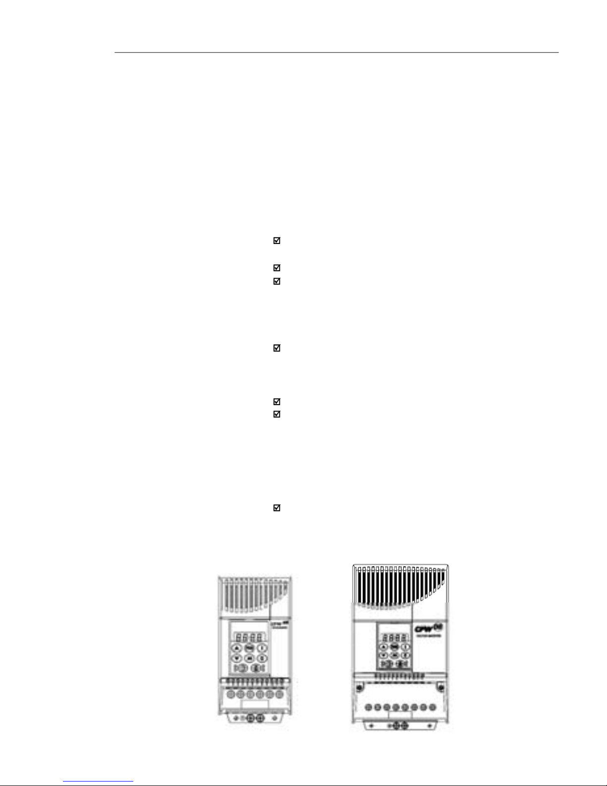
CHAPTER 2 - GENERAL INFORMATION
Figure 2.4 - Description and location of the nameplates on the CFW-08
2.4 CFW-08IDENTIFICATION
Lateral Label of the CFW-08
Frontal Nameplate of the CFW-08 (under the keypad)
EliwellPart Number
SerialNumber
CFW-08Model (IntelligentCode)
SoftwareVersion
ManufacturingDate
CertificationStiker
EWCFW080130S0
12345678 V1.234
1234567890 20/02/2008
CFW-08Model
(IntelligentCode)
RatedOutput Data
(Voltage,Frequency)
SoftwareVersion
ManufacturingDate
EliwellPart Number
SerialNumber
RatedInputData
(Voltage, Current,etc)
Page 24

24
CHAPTER 2 - GENERAL INFORMATION
Note: All models include internal Class A RFI filter, Breake Chopper and have
thefollowing standard Inputs & Outputs:
- 2 Analog Inputs
- 1 Analog Output
- 4 Digital Inputs
- 2 Relay Outputs
EWCFW-08 0043 S 0
Rated Output
Current for:
0043 = 4.3A
0065 = 6.5A
0100 = 10A
0130 = 13A
0160 = 16A
0240 = 24A
0300 = 30A
380Vac to
480Vac
3-phase
Supply
Communication
Option
0 = No
communication
S = RS485
(Modbus RTU)
communication
EndCode
Eliwell
Series 08
Frequency
Inverter
HOW TO SPECIFY THE CFW-08 MODEL:
Page 25

25
CHAPTER 2 - GENERAL INFORMATION
Forthe effectofthiscode, the standardproductis conceived
asfollows:
-CFW-08withstandardcontrol board.
- Degree of protection: Nema 1 for the models 22 A,
28 A and 33 A/ 200-400 V and also 13 A,16 A, 24 A
and 30 A/380-480 V, IP20 for the other models.
CFW-08 Plus - A1 is composed of the inverter and the
controlboard 1. Example: CFW080040S2024POA1Z.
CFW-08 Plus - A2 is composed of the inverter and the
control board 2. Example: CFW080040S2024POA2Z.
Thesemodelsarefactorysetforbipolaranaloginputs(-10V
to +10 V).
Thisconfigurationislostwhenthefactorydefaultparameters
areloaded (P204 = 5). Referto the detailed descriptionof
parametersP204 andP235for furtherinformation.
CFW-08 Plus -A3 is composed of the inverter, the KFBCO-CFW08kitandtheCANopencommunicationprotocol.
Example:CFW-080040S2024POA3Z.
CFW-08 Plus -A4 is composed of the inverter, the KFBDN-CFW08kitandtheDeviceNetcommunicationprotocol.
Example:CFW080040S2024POA4Z.
CFW-08 Multipump - A5 is composed of the inverter and
thecontrolboard5,usedformultipumpsystemapplications.
7.0A, 16.0 A, 22 A, 28A and 33A /200-240 V and for all
380-480 V models are just available with three-phase
powersupply.
A Category C2 RFI filter (optional) can be installed inside
the inverter in models 7.3 A and 10 A/200-240 V (singlephase) and 2.7 A, 4.3A, 6.5 A, 10 A, 13A, 16 A, 24 A and
30A/380-480 V. Models 1.6A, 2.6A and 4.0A/200-240 V
(single-phase)and1.0A,1.6A, 2.6Aand4.0A/380-480V
can be provided mounted on a footprint Category C2 RFI
filter(optional).
Thelistingoftheexistingmodels(voltage/current)isshown
initem 7.1.
Page 26

26
CHAPTER 2 - GENERAL INFORMATION
The CFW-08 issupplied in cardboard boxes.
Theoutsideofthepackingboxhasanameplatethatisidentical
tothat on the CFW-08.
Please check if the CFW-08is the one you ordered.
Checkif the:
CFW-08nameplatedatamatcheswithyourpurchaseorder.
Theequipmenthas not beendamaged duringtransport.
Ifanyproblem isdetected,contactthe carrier immediately.
If the CFW-08 is not installed immediately,store it in a clean
anddryroom (storage temperatures between-25 °C [-13 °F]
and 60 °C [140 ºF]). Cover it to protect against dust, dirt or
othercontamination.
ATTENTION!
When theinverterisstoredforalongtime,itisrecommended
to power the inverter up for 1 hour every year.Make sure to
use a power supply with the following characteristics for all
models (200-240 V or 380-480 V): 220 V, single-phase or
three-phase,50 Hz or 60 Hz, withoutconnectingthemotorto
thedriveoutput.Afterpoweringup thedrive,keepit off for24
hoursbeforeusingitagain.
2.5 RECEIVINGAND
STORING
Page 27
27
CHAPTER3
INSTALLATION ANDCONNECTION
Thischapterdescribesthe proceduresfor the electrical and
mechanicalinstallationof the CFW-08.Theseguidelines
andsuggestionsmust be followedforproperCFW-08
operation.
The location of the inverter installation is an important factor
to assure good performance and long useful life for its
components. For proper installation, we make the following
recommendations:
Avoid direct exposureto sunlight, rain, high moisture and
sea air;
Avoidexposuretoexplosiveorcorrosivegasesandliquids;
Avoid exposure to excessive vibration, dust, oil or any
conductiveparticlesin the air.
Environment conditions:
Temperature: 0 ºC to 40 ºC (32 ºF to 104 ºF ) - nominal
conditions.From40 ºC to50 ºC (32ºFto122 ºF)- with2 %
currentderatingfor each 1 ºC (1.8 ºF) degreeabove40 ºC
(104ºF).
Relativeairhumidity:5 %to90 % - non-condensing.
Maximumaltitude: 1000m(3,300ft) - nominalconditions.
From 1000 m to 4000 m (3,300 to 13123.3 ft) - with 1 %
currentreduction for each 100 m (328 ft) above 1000 m
(3,300ft).
From2000 m (6561.6ft) to 4000 m (13123.3ft)- a voltage
reduction of 1.1 % every 100 m (328 ft) above 2000 m
(6561.6ft).
Pollution degree: 2 (according toEN50178 and UL508C)
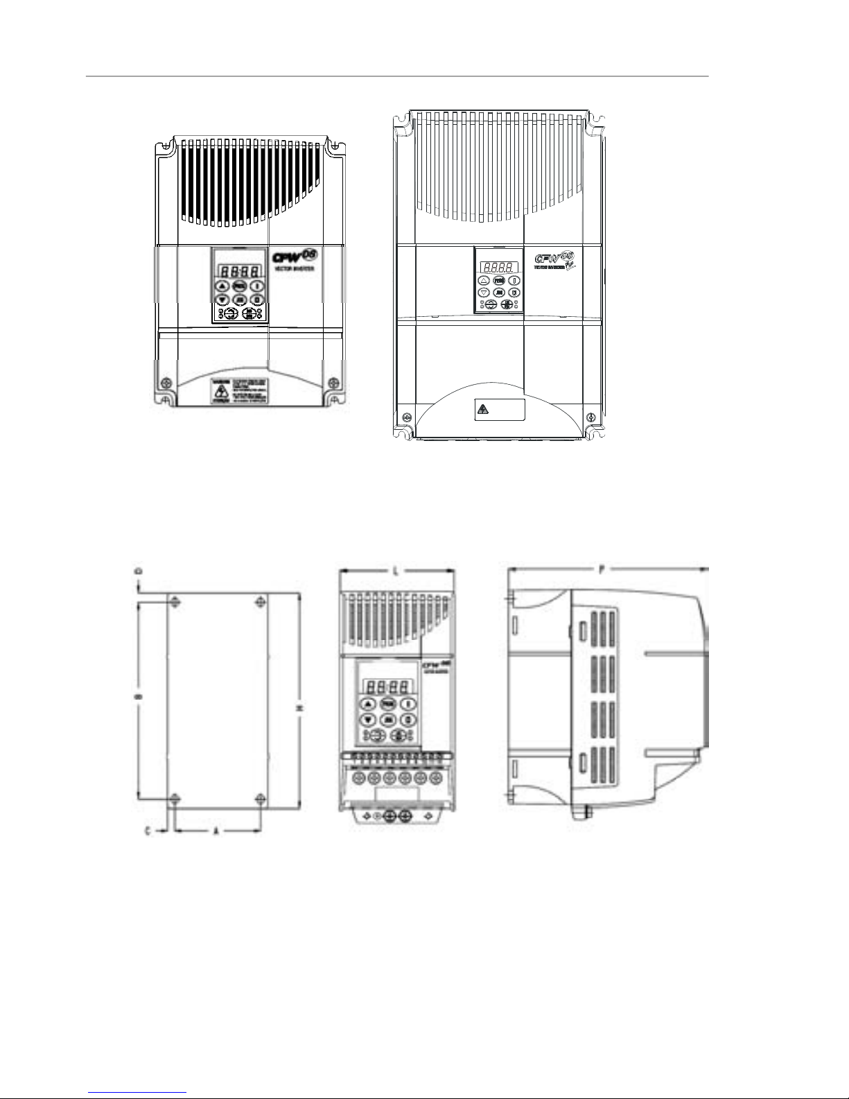
The figure 3.1 and thetable 3.1, provides external mounting
specifications,and externalfixingholes of theCFW-08.
3.1 MECHANICAL
INSTALLATION
3.1.1 Environment
3.1.2 CFW-08Mounting
Specifications
Figure 3.1 - CFW-08 mounting specifications
Page 28
28
CHAPTER 3 - INSTALLATION AND CONNECTION
Figure 3.1 (cont.) - CFW-08 mounting specifications
VIEW OF THE
MOUNTINGBASE
FRONTAL
VIEW
LATERALVIEW
1MIN. APÓSA DESENERGIZAÇÃO.
-SOMENTE REMOVAATAMPA
-LEIA OMANUAL DEINSTRUÇÕES.
ATENÇÃO
-READ THE INSTRUCTIONSMANUAL.
AFTER1 MIN. POWERHAS BEEN
-ONLY REMOVETERMINAL COVER
WARNING
DISCONNECTED.
Page 29

29
CHAPTER 3 - INSTALLATION AND CONNECTION
Inverter
Model
1.6A / 200-240 V
2.6A / 200-240 V
4.0A / 200-240 V
7.0A / 200-240 V
7.3A / 200-240 V
10A / 200-240 V
16A / 200-240 V
22A/200-240V
28A/200-240V
33A/200-240V
1.0A / 380-480 V
1.6A / 380-480 V
2.6A / 380-480 V
2.7A / 380-480 V
4.0A / 380-480 V
4.3A / 380-480 V
6.5A / 380-480 V
10A / 380-480 V
13A / 380-480 V
16A / 380-480 V
24A/380-480V
30A/380-480V
Width L
mm
(in)
75
(2.95)
75
(2.95)
75
(2.95)
75
(2.95)
115
(4.53)
115
(4.53)
115
(4.53)
143
(5.63)
182
(7.16)
182
(7.16)
75
(2.95)
75
(2.95)
75
(2.95)
115
(4.53)
75
(2.95)
115
(4.53)
115
(4.53)
115
(4.53)
143
(5.63)
143
(5.63)
182
(7.16)
182
(7.16)
HeightH
mm
(in)
151
(5.95)
151
(5.95)
151
(5.95)
151
(5.95)
200
(7.87)
200
(7.87)
200
(7.87)
203
(7.99)
290
(11.41)
290
(11.41)
151
(5.95)
151
(5.95)
151
(5.95)
200
(7.87)
151
(5.95)
200
(7.87)
200
(7.87)
200
(7.87)
203
(7.99)
203
(7.99)
290
(11.41)
290
(11.41)
Depth P
mm
(in)
131
(5.16)
131
(5.16)
131
(5.16)
131
(5.16)
150
(5.91)
150
(5.91)
150
(5.91)
165
(6.50)
196
(7.71)
196
(7.71)
131
(5.16)
131
(5.16)
131
(5.16)
150
(5.91)
131
(5.16)
150
(5.91)
150
(5.91)
150
(5.91)
165
(6.50)
165
(6.50)
196
(7.71)
196
(7.71)
A
mm
(in)
64
(2.52)
64
(2.52)
64
(2.52)
64
(2.52)
101
(3.98)
101
(3.98)
101
(3.98)
121
(4.76)
161
(6.33)
161
(6.33)
64
(2.52)
64
(2.52)
64
(2.52)
101
(3.98)
64
(2.52)
101
(3.98)
101
(3.98)
101
(3.98)
121
(4.76)
121
(4.76)
161
(6.33)
161
(6.33)
B
mm
(in)
129
(5.08)
129
(5.08)
129
(5.08)
129
(5.08)
177
(6.97)
177
(6.97)
177
(6.97)
180
(7.08)
260
(10.23)
260
(10.23)
129
(5.08)
129
(5.08)
129
(5.08)
177
(6.97)
129
(5.08)
177
(6.97)
177
(6.97)
177
(6.97)
180
(7.09)
180
(7.09)
260
(10.23)
260
(10.23)
C
mm
(in)
5
(0.20)
5
(0.20)
5
(0.20)
5
(0.20)
7
(0.28)
7
(0.28)
7
(0.28)
11
(0.43)
11
(0.43)
11
(0.43)
5
(0.20)
5
(0.20)
5
(0.20)
7
(0.28)
5
(0.20)
7
(0.28)
7
(0.28)
7
(0.28)
11
(0.43)
11
(0.43)
11
(0.43)
11
(0.43)
D
mm
(in)
6
(0.24)
6
(0.24)
6
(0.24)
6
(0.24)
5
(0.20)
5
(0.20)
5
(0.20)
10
(0.39)
10
(0.39)
10
(0.39)
6
(0.24)
6
(0.24)
6
(0.24)
5
(0.20)
6
(0.24)
5
(0.20)
5
(0.20)
5
(0.20)
10
(0.39)
10
(0.39)
10
(0.39)
10
(0.39)
Mounting
Screw
M4
(5/32)
M4
(5/32)
M4
(5/32)
M4
(5/32)
M4
(5/32)
M4
(5/32)
M4
(5/32)
M5
(3/16)
M5
(3/16)
M5
(3/16)
M4
(5/32)
M4
(5/32)
M4
(5/32)
M4
(5/32)
M4
(5/32)
M4
(5/32)
M4
(5/32)
M4
(5/32)
M5
(3/16)
M5
(3/16)
M5
(3/16)
M5
(3/16)
Weigth
kg
(lb)
1.0
(2.2)
1.0
(2.2)
1.0
(2.2)
1.0
(2.2)
2.0
(4.4)
2.0
(4.4)
2.0
(4.4)
2.5
(9.8)
6
(2.36)
6
(2.36)
1.0
(2.2)
1.0
(2.2)
1.0
(2.2)
2.0
(4.4)
1.0
(2.2)
2.0
(4.4)
2.0
(4.4)
2.0
(4.4)
2.5
(5.5)
2.5
(5.5)
6
(2.36)
6
(2.36)
Degreeof
Protection
IP20 / Nema 1
(*)
IP20 / Nema 1
(*)
IP20 / Nema 1
(*)
IP20 / Nema 1
(*)
IP20 / Nema 1
(*)
IP20 / Nema 1
(*)
IP20 / Nema 1
(*)
IP20/Nema 1
IP20/Nema 1
IP20/Nema 1
IP20 / Nema 1
(*)
IP20 / Nema 1
(*)
IP20 / Nema 1
(*)
IP20 / Nema 1
(*)
IP20 / Nema 1
(*)
IP20 / Nema 1
(*)
IP20 / Nema 1
(*)
IP20 / Nema 1
(*)
IP20 / Nema 1
IP20 / Nema 1
IP20 / Nema 1
IP20 / Nema 1
Dimensions Fixing base
Table 3.1 - CFW-08 dimensions for mechanical installation of the several models
(*) These modelsare Nema 1 onlywith the KN1-CFW08-MX optional.
Note: Please check availability of model with our sales office.
Page 30
30
CHAPTER 3 - INSTALLATION AND CONNECTION
When installing the CFW-08,free space around theinverter
must be left as indicated in figure 3.2. Table 3.2 shows the
required free spaces.
Installtheinverterinverticalpositionaccordingtothefollowing
recommendations:
1)Installtheinverterona flatsurface.
2)Donotinstallheatsensitivecomponentsimmediatelyabove
theinverter.
ATTENTION!
When inverters are installed side by side, maintain the
minimumrecommendeddistanceB.
When inverters are installed top and bottom, maintain the
minimum recommended distance A+ C and deflect the hot
aircomingfrom the inverterbelow.
ATTENTION!
Provide independent conduits for signal, control and power
conductorsseparation(refertoitem3.2-ElectricalInstallation).
Useseparateconduitsortrunkingforcontrolandpowerwiring
(seeitem 3.2 - Electrical Installation).
Figure 3.2 - Free spaces for cooling
3.1.3 Positioningand Fixing
Page 31

31
CHAPTER 3 - INSTALLATION AND CONNECTION
CFW-08Model
1.6A / 200-240 V
2.6A / 200-240 V
4.0A / 200-240 V
7.0A / 200-240 V
1.0A / 380-480 V
1.6A / 380-480 V
2.6A / 380-480 V
4.0A / 380-480 V
7.3A / 200-240 V
10A / 200-240 V
16A / 200-240 V
2.7A / 380-480 V
4.3A / 380-480 V
6.5A / 380-480 V
10A / 380-480 V
22A / 200-240 V
13A / 380-480 V
16A / 380-480 V
28A/200-240V
33A/200-240V
24A/380-480V
30A/380-480V
A B C D
30 mm 1.18 in 5mm 0.20 in 50 mm 2 in 50mm 2 in
35 mm 1.38 in 15 mm 0.59 in 50 mm 2 in 50 mm 2 in
40 mm 1.57 in 30 mm 1.18 in 50 mm 2 in 50 mm 2 in
50 mm 2 in 40mm 1.57 in 60 mm 2.36 in 50 mm 2 in
Table 3.2 - Recommended free spaces
When invertersare installed inside closed metallic panelsor
boxes provide suitable air exhaustion by ensuring that the
ambient temperature remains within the allowed range. For
wattlosses refer toitem9.1of this manual.
For reference, table 3.3 shows the cooling airflow for each
invertermodel.
Inverter Cooling Method: internal fan, flow direction from
thebottom to thetop.
3.1.3.1 PanelMounting
Table 3.3 - Cooling air flow requirements
CFW
-
08 Inverter Model
CFM
I/s
m3/min
4.0 A, 7.0 A/200 V
2.6 A, 4.0 A/400 V
6.0 2.8 0.17
7.3 A, 10 A, 16 A/200 V
6.5 A, 10 A/400 V
18.0 8.5 0.51
13 A, 16 A/400 V 18.0 8.5 0.51
22 A/200 V 22.0 10.4 0.62
28 A/200 V
24 A/400 V
36.0 17.0 1.02
33 A/200 V
30 A/400 V
44.0 20.8 1.25
Page 32

32
CHAPTER 3 - INSTALLATION AND CONNECTION
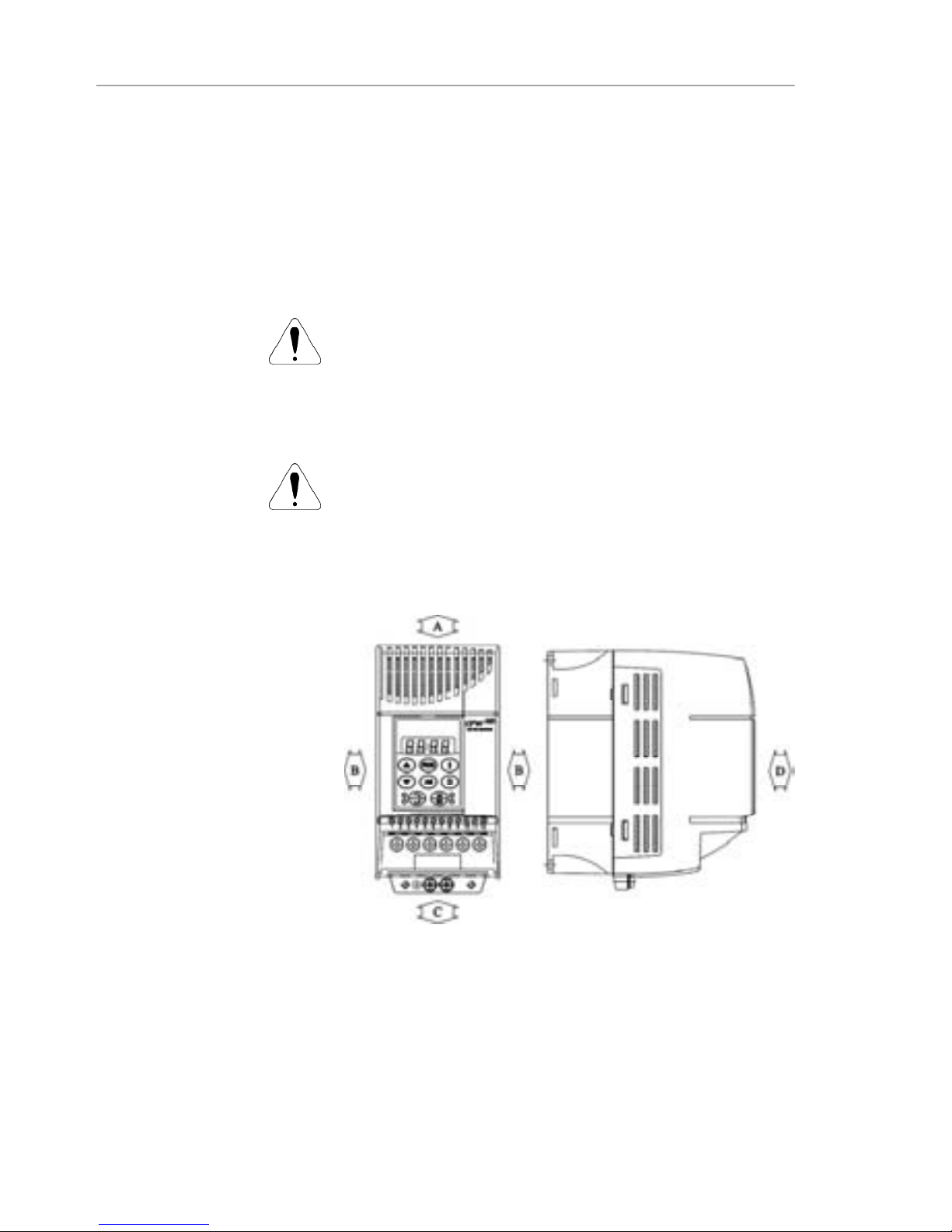
3.1.3.2 SurfaceMounting Figure 3.3 shows the surface installation procedures of the
CFW-08.
Figure 3.3 - Mounting procedures for CFW-08
3.2 ELECTRICAL
INSTALLATION
DANGER!
The information below will be a guide to achieve a proper
installation. Also follow all applicable local standards for
electricalinstallations.
DANGER!
Be sure the AC input power has been disconnected before
makinganyterminalconnection.
DANGER!
Do not use the CFW-08 as an emergency stop device. For
thispurposeprovideother additional mechanical means.
Thepowerconnectionterminalscan beofdifferentsizesand
configurations,dependingon theinvertermodel,as shownin
figure3.4.
Descriptionofthe powerterminals:
L/L1,N/L2 and L3 (R, S ,T):AC power supply.
Themodels oftheline voltage200-240V (excepting7.0A,
16A, 22A, 28A, and33A) canbeoperatedon twophases
(single-phaseoperation)withoutratedcurrentreduction.In
this case theAC powersupply can be connected to any 2
terminalsof the3inputsterminals.
U,V,W: connectiontothemotor.
3.2.1 Power/ Grounding
Terminals
AIR FLUX
Page 33

33
CHAPTER 3 - INSTALLATION AND CONNECTION
-UD:negativepoleof theDClinkcircuitisnotavailable on
themodels 1.6A-2.6A-4.0A-7.0A/200-240Vandmodels
1.0 A-1.6 A-2.6 A-4.0 A/380-480 V. It is used when the
invertersuppliedbyDC voltage(withtheterminal+UD).In
order to avoid an incorrect braking resistor connection
(mountedoutsidetheinverter),thereisaprotectiverubber
plug on this terminal, which must be removed if the –UD
terminalhastobe used.
BR:Connectionforthebrakingresistor.
Notavailableonthemodels1.6A-2.6A-4.0A-7.0A/200-240V
andonthemodels1.0A-1.6A-2.6A-4.0A/380-480V.
+UD: positive pole of the DC link circuit, notavailable on
the models 1.6A-2.6A-4.0A-7.0A/200-240 V and on the
models 1.0 A-1.6 A-2.6 A-4.0 A/380-480 V. It is used to
connectthebrakingresistor(withtheBR terminal)orwhen
the inverter shall be supplied by with DC voltage (jointly
withthe–UDterminal.
DCR: Connection for the external DC link circuit inductor
(optional).Itis onlyavailableonthemodels28Aand 33A/
200-240 V and on the models 24A and 30 A/380-480 V.
c) 22 A/200-240 V and 13-16 A/380-480 V models
b)7.3-10-16A/200-240V and 2.7-4.3-6.5-10A/380-480V models
a)1.6-2.6-4.0-7.0A/200-240V and 1.0-1.6-2.6-4.0A/380-480V models
Figure 3.4 a) to c) - Power terminals
L3 U V WL/L1
N/L2
-Ud BR +Ud
L3L/L1 N/L2
U V W
1R2S3T4U5V6W7
-UD8BR9+UD
LINE
MOTOR
Page 34

34
CHAPTER 3 - INSTALLATION AND CONNECTION
3.2.2 Location of the Power
Terminals,Grounding
TerminalsandControl
TerminalConnections
ControlXC1
Power
Grounding
a)1.6-2.6-4.0-7.0-7.3-10-16A/200-240V and
1.0-1.6-2.6-2.7-4.0-4.3-6.5-10A/380-480V models
Figure 3.5 a) and b) - Location of the power,grounding and
control connections
b)22-28-33A/200-240 V and 13-16-24-30A/380-480V models
ControlXC1
Power
Grounding
Figure 3.4 (cont.) d) - Power terminals
d) 28-33A/200-240 V and 24-30 A/380-480 V models
1R2S3T4U5V6W7
-UD8BR9+UD
LINE
MOTOR
10
DCR
Page 35

35
CHAPTER 3 - INSTALLATION AND CONNECTION
3.2.3 Power/Grounding
Wiringand
Circuit Breakers
ATTENTION!
Install the inverter and power cables distant from sensitive
equipmentandwiringsby0.25m (0.82ft),forinstancePLCs,
temperaturecontrollers,thermocouplecables,etc.
Usetherecommendedwirecrosssectionandcircuitbreakers
as shownin table 3.4. Use onlycopperwire (70 ºC [158 ºF]).
NOTE!
Thewire sizing in table3.4shallbeusedas referencevalues
only. The exact wire sizing depends on the installation
conditionsand themaximumacceptable line voltage drop.
Therecommendedtightening torqueisshownin table3.5.
ATTENTION!
The use of mini circuit breakers(MBU) is notrecommended
duetothelevelofthemagneticprotection.
Table 3.4 - Recommended wiring and circuit breakers – use only copper wire (70 ºC [158 ºF])
Page 36

36
CHAPTER 3 - INSTALLATION AND CONNECTION
Model
1.6A / 200-240 V
2.6A / 200-240 V
4.0A / 200-240 V
7.0A / 200-240 V
7.3A / 200-240 V
10.0A / 200-240 V
16.0A / 200-240 V
22.0A / 200-240 V
28.0A / 200-240 V
33.0A / 200-240 V
1.0A / 380-480 V
1.6A / 380-480 V
2.6A / 380-480 V
2.7A / 380-480 V
4.0A / 380-480 V
4.3A / 380-480 V
6.5A / 380-480 V
10.0A / 380-480 V
13.0A / 380-480 V
16.0A / 380-480 V
24.0A / 380-480 V
30.0A / 380-480 V
GroundingWiring
N.m Lbf.in
0.5 4.34
0.5 4.34
0.5 4.34
0.5 4.34
0.5 4.34
0.5 4.34
0.5 4.34
0.5 4.34
0.5 4.34
0.5 4.34
0.5 4.34
0.5 4.34
0.5 4.34
0.5 4.34
0.5 4.34
0.5 4.34
0.5 4.34
0.5 4.34
0.5 4.34
0.5 4.34
0.5 4.34
0.5 4.34
Power Cables
N.m Lbf.in
1.0 8.68
1.0 8.68
1.0 8.68
1.0 8.68
1.76 15.62
1.76 15.62
1.76 15.62
1.76 15.62
1.76 15.62
1.76 15.62
1.2 10.0
1.2 10.0
1.2 10.0
1.76 15.62
1.2 10.0
1.76 15.62
1.76 15.62
1.76 15.62
1.76 15.62
1.76 15.62
1.76 15.62
1.76 15.62
Table 3.5 - Recommendedtighteningtorque for powerand grounding connections
3.2.4 PowerConnections
a) 1.6-2.6-4.0-7.0A/200-240V and 1.0-1.6-2.6-4.0A/380-480V models - Threephase powersupply
TypeofScrewdriverfor
thePowerTerminal
Philips Number PH2
Philips Number PH2
Philips Number PH2
Philips Number PH2
Philips Number PH2
Philips Number PH2
Philips Number PH2
PhilipsNumber PH2
PozidrivNumberPZ2
PozidrivNumber PZ2
PhilipsNumber PH2
Philips Number PH2
Philips Number PH2
Philips Number PH2
Philips Number PH2
Philips Number PH2
Philips Number PH2
Philips Number PH2
Philips Number PH2
Philips Number PH2
PozidrivNumber PZ2
PozidrivNumber PZ2
Figure 3.6 a) - Power and groundingconnections
PE
R
S
T
PowerSupply CircuitBreaker
PE
T
Q1
R S
T
U V W
PE
Shielding
PE W
V
U
Page 37

37
CHAPTER 3 - INSTALLATION AND CONNECTION
c) 1.6-2.6-4.0-7.3-10A / 200-240 V models - Single phase power supply
Figure 3.6 b) and c) - Powerand grounding connections
(*) Incase of single-phase power supplywith phase and neutral cable, connect onlythe phase cable to the
circuit breaker.
(**) In the 1.6 A -2.6A and 4.0 A models, the terminals to connect the braking resistor are not available.
PE
PE
T
Q1
R S
T U V W
PE
Shielding
PE
-Ud BR
+Ud
Braking
Resistor
(**)
W V U
Phase
Neutral
PowerSupply
Circuit Breaker
(*)
b) 7.3-10-16-22A/200-240V and 2.7-4.3-6.5-10-13-16A/380-480V models - Three phasepower supply
PE
R
S
T
PowerSupply
PE
T
Q1
R S
T U V W
PE
Shielding
PE
-Ud BR
+Ud
Braking
Resistor
W V U
CircuitBreaker
Page 38

38
CHAPTER 3 - INSTALLATION AND CONNECTION
Figure 3.6 d) - Power and groundingconnections
d) 28-33A / 200-240V and 24-30 A/ 380-480 V models - Three phase power supply
DANGER!
Provide an AC disconnecting switch to switch OFF the input
powertotheinverter.Thisdeviceshalldisconnecttheinverter
from the AC input supply when required (e. g. during
maintenanceservices).
ATTENTION!
Acontactororanotherdevicethatfrequentlydisconnectsand
reapplies the AC supply to the inverter in order to start and
stop the motor may cause damage to the inverter power
section.The driveis designedto usecontrolinput signals for
startingandstoppingthemotor.If used,the inputdevicemust
not exceed one operation every 6 minutes otherwise the
invertermay be damaged.
ATTENTION!
TheAC input for the inverter must have a grounded neutral
conductor.
NOTE!
TheACinputmustbecompatiblewiththeinverterratedvoltage
Power supply line capacity:
30kArms symmetrical amperes, 200-480 Vacmaximum,
whenprotected by fusesratedmaximum of 200 % device
inputcurrent.Voltageisthesameasthedevice maximum
inputvoltage. Inorderto comply withtheULstandard,UL
recognizedfuses must be used.
3.2.4.1 ACInputConnection
PE
T
Q1
R S
T
U
V
W
PE
Shielding
PE
-Ud BR
+Ud
Braking Resistor
W V U
Phase
PowerSupply
DCR
DCLink
Inductor
(Optional)
PE
R
S
T
CircuitBreaker
Page 39

39
CHAPTER 3 - INSTALLATION AND CONNECTION
3.2.4.3 Grounding
Connections
IftheCFW-08isinstalledinnetworkswhichcansupplymore
than 30.000 Arms, you must provide suitable protection
circuitssuchas fuses and circuitbreakers.
DC link inductor / line reactors
Therequirementsforuseof line reactorsor DC linkinductor
dependonseveral applicationfactors.Refer to item 8.21.
NOTE!
Capacitorsfor power factor correctionarenotrequiredatthe
input(L/L1,N/L2,L3orR,S,T)andtheymustnotbeconnected
atthe output(U,V,W).
The inverter is provided with electronic protection against
motoroverload.This protection must be setaccording to the
specificmotor.Whenthesameinverterdrivesseveralmotors,
use individual overload relays for each motor. Maintain the
electricalcontinuityof the motor cableshield.
ATTENTION!
If a disconnect switch or a contactor is inserted in the motor
supplyline, do not operate them with motor running or when
inverter is enabled. Maintain the electrical continuity of the
motorcable shield.
Dynamic braking (DB)
When inverters with dynamic braking(DB) are used, the DB
resistor shall be mounted externally. Size it according to the
application,notexceedingthemaximumcurrentofthebraking
circuit. For the connection between inverter and the braking
resistor, use twisted cable. Provide physical separation
betweenthis cable and thesignal and control cables. When
the DB resistor is mounted inside the panel, consider watt
lossgeneratedwhendefiningthe panel ventilation.
DANGER!
Theinverter must be grounded to aprotectiveearth (PE)for
safetypurposes.
The earth or ground connection must comply with the local
regulations.Forgrounding,usecableswithcrosssectionsas
indicated in table 3.4. Make the ground connection to a
grounding bar or to the general grounding point (resistance
10 ohms).
DANGER!
Do not share the ground wiring with other equipment that
operateswithhighcurrents(forinstance:highvoltagemotors,
weldingmachines,etc).If severalinvertersareusedtogether,
refertofigure 3.7.
3.2.4.2 Output
Connections
Page 40

40
CHAPTER 3 - INSTALLATION AND CONNECTION
ATTENTION!
TheAC input for the inverter must have a grounded neutral
conductor.
EMI – Electromagnetic interference
When electromagnetic interference (EMI) generated by the
inverterinterferesin theperformanceofotherequipment,use
shieldedwires,orinstallthemotorwiresin metallicconduits.
Connect one end of the shielding to the inverter grounding
pointandtheotherendtothemotorframe.
Motor frame
Alwaysgroundthemotorframe.Groundthemotorinthepanel
wherethe inverterisinstalledorgroundittotheinverter.The
inverter output wiring must be laid separatelyfrom the input
wiringas wellasfrom the control and signalcables.
NOTE!
Donotuseneutralconductorfor groundingpurposes.
Figure 3.7 - Grounding connections for more than one inverter
GROUNDING BAR
INTERNAL TO THE PANEL
Page 41

41
CHAPTER 3 - INSTALLATION AND CONNECTION
3.2.5 Signaland Control
Connections
The signal connections(analog inputs/outputs) and control
connections (digital inputs and relay outputs) are made on
the XC1 connector of control board (referto the location in
figure 3.5, item3.2.2).
There are two configurations for the control board: standard
version (CFW-08 line)andPlusversion(CFW-08Plusline),
asshownbelow:
Figure 3.8 - XC1 control terminal description (standard control board - CFW-08)
Note: NC = NormallyClosed Contact, NO = NormallyOpen Contact.
XC1Terminal
1 DI1
2 DI2
3 DI3
4 DI4
5 GND
6
AI1or
DI5or
PTC1
7 +10 V
8 GND
9
10 N.C.
11 Commom
12 N.O.
Description
FactoryDefault Function
Digital Input 1
GeneralEnable
Digital Input 2
FWD / REV
Digital Input 3
Reset
Digital Input 4
Start/Stop
0V Reference
Analog Input 1 or Digital Input 5
orPTC Input
Frequency/ SpeedReference
(remotemode)
PotentiometerReference
0V Reference
NotUsed
Relay Output 1 - N.C. Contact
No Fault (P277 = 7)
Relay1 Common Point
Relay 1 - N.O. Contact
No Fault (P277 = 7)
Specifications
4 isolates digital inputs
- Logic NPN
Minimum high level: 10 Vdc
Maximum high level: 30 Vdc
Maximum low level: 3 Vdc
- Logic PNP
Maximum low level: 10 Vdc
Minimum high level: 21.5 Vdc
Maximum high level: 30 Vdc
Inputcurrent: -11mA
Maximum input current: -20 mA
Not connected to PE
( 0 to10) Vdc (0 to 20) mA (4 to 20)
mA(figure3.10)
Impedance:100 k (voltage input)
and 500 (current input).
- Linearity error < 0,25 %
- Maximum voltage input: 30 Vdc
ForfurtherinformationrefertoP235
detailedparameterdescription
+10 Vdc, ± 5 %, capacity: 2 mA
Contact capacity:
0.5 A / 250 Vac
Relay 1
10 12
11
CCW
CW
5k
FactoryDefault
Settings
Page 42

42
CHAPTER 3 - INSTALLATION AND CONNECTION
Figure 3.9 - Description of the XC1 connector for the control board A1 (CFW-08 Plus), control board A2
(CFW-08 Plus with AIs -10 V to +10 V), control board A3 (CFW-08 Plus with CANopen protocol) and control
boardA4 (CFW-08 Plus with DeviceNet protocol)
Connector
XC1
1 DI1
2 DI2
3 DI3
4 DI4
5 GND
6 AI1or
DI5or
PTC1
7 +10 V
8 AI2or
DI6or
PTC2
9 AO
10 N.C
11 Commom
12 N.O.
Description
FactoryDefault Function
Digital Input 1
NoFunctionorGeneralEnable
Digital Input 2
FWD / REV
Digital Input 3
Reset
Digital Input 4
No Function or Start/Stop
0V Reference
AnalogInput1orDigitalInput5
orPTC1 Input
Frequency/SpeedReference
(remotemode)
PotentiometerReference
Analog Input 2 or Digital Input
Digital 6 or PTC2 Input
NotUsed
AnalogOutput
Output Frequency (Fs)
Relay 2 - N.C. Contact
Fs>Fx (P279 = 0)
RelaysCommon Points
Relay 1 - N.O. Contact
No Fault (P277 = 7)
Specifications
4 isolates digital inputs
- Logic NPN
Minimum high level: 10 Vdc
Maximum high level: 30 Vdc
Maximum low level: 3 Vdc
- Logic PNP
Maximum low level: 10 Vdc
Minimum high level: 21.5 Vdc
Maximum high level: 30 Vdc
Inputcurrent: -11mA
Maximum input current: -20 mA
Not connected to PE
(0to10)Vdcor(0to20)mAor(4to20)mA
and (-10 to +10) Vdc
(*)
(figure 3.10)
Impedance:100k (voltage input) and
500(currentinput)
- Linearity error < 0,25 %
- Maximum voltage input: 30 Vdc
For further information refer to P235
detailedparameterdescription
+10 Vdc, ± 5 %, capacity: 2 mA
(0to10)Vdc or (0 to 20) mA or(4 to
20)mA and (-10 to +10) Vdc
(*)
(figure
3.10) Impedance:100 k (voltage
input) and 500 (currentinput)
- Linearity error< 0.25%
- Maximumvoltage input: 30 Vdc
Forfurtherinformationrefer toP239
detailedparameterdescription
(0to10)Vdcor(0to20)mAor(4to20)mA,
RL 10k Resolution: 8 bits
Linearity Error < 0.25 %
Contact capacity:
0.5 A / 250 Vac
Relay 1
11
Relay 2
12 10
RPM
-
+
CCW
CW
CCW
CW
10k
Note: NC = NormallyClosed Contact, NO = NormallyOpen Contact.
(*)
Thisoption is availableonly for versionA2of thecontrol board (refertoitem 2.4).
In version A2 the linearity error is smaller than 0.50 %.
10k
FactoryDefault
Settings
Refer to item 2.4for additional information onthecontrol boards.
Page 43

43
CHAPTER 3 - INSTALLATION AND CONNECTION
AI1AODI AI2
Figure3.10 - Jumperspositionfor selectingthe analoginputs andoutputs operation mode(voltage- 0 to 10 Vdc
or current - 0 to 20 mA / 4 to 20 mA) as well as the digitalinputs operation mode(highlogic level - PNP or low
logic level - NPN). Refer to the digital inputs definition on items 3.2.5.1 and 3.2.5.2
I/O
DI1to DI4
AO
AI1
AI2
FactoryDefault Setting
Refer to the parameters P263,
P264, P265 andP266
OutputFrequency
Frequency/ SpeedReference
(remotemode)
NoFunction
DIP
Switch
S1:1
S1:2
S1:3
S1:4
Selection
OFF: digital inputs as low active (NPN)
ON: digital inputs as high active (PNP)
ON: (0 to 10) Vdc
OFF: (4 to 20) mA or (0 to 20) mA
OFF: (0 to 10) Vdc or DI5
ON: (4 to 20) mA or (0 to 20) mA or PTC
OFF: (0 to 10) Vdc or DI6
ON: (4 to 20) mA or (0 to 20) mA or PTC
Table 3.6 - Dip switch configuration (inputs and outputs)
Asadefault,theanalog inputs and outputsaresettovoltage
mode (0 to 10) Vdc and the digital inputs are set to active
(NPNlogic).Changeitbyusing DIP switchS1 (refer to figure
3.10) on the control board and by setting parameters P235,
P239 and P253 (refer to table 3.6).
NOTE!
If it'suseda(4to20)mA signal,setparameterP235,P239
and P253 that defines the signal type atAI1,AI2 and AO
respectively.
The parameters related to the analog inputs are: P221,
P222,P234,P235,P236,P238,P239,P240,P251,P252,
P253.
Page 44

44
CHAPTER 3 - INSTALLATION AND CONNECTION
Inverter side
Insulatewith tape
Figure 3.11- Shield connection
Connect to earth: bolts are
located on the heatsink
Donot ground
During the signal and control wire installation note the
following:
1) Cable cross section: (0.5to 1.5) mm²/(20 to 14)AWG
2)MaximumTorque:0.50N.m(4.50lbf.in).
3) XC1 wiring must be connected with shielded cables and
installedat least 10 cm (3.9in) minimum separatelyfrom
otherwiring (power,control at 110/220V, etc) for lengths
up to 100 m (330 ft) and 25 cm (9.8 in) minimum for total
lengthsover100 m(330ft). Ifthecrossingof thesecables
isunavoidable, installthemperpendicular,maintaininga
mimimumseparationdistanceof 5cm(2in)atthecrossing
point.
Connectthe shield as shownbelow:
4) Forwiringdistances longerthan50m(150ft),itisnecessary
touse galvanic isolators for the XC1:5 to 9 signals.
5) Relays, contactors, solenoids or eletromagnetic braking
coilsinstalledneartheinverterscangenerateinterferences
inthecontrolcircuit.Toeliminatethisinterference,connect
RC suppressor in parallel with the coils of AC relays.
Connectfree-wheeling diode incase of DC relays.
6) When external keypad (HMI) is used, separete the cable
thatconnectsthekeypad to the inverter fromothercables,
maintaining aminimumdistanceof10cm(3.9 in)between
them.
7) When analog reference (AI1 or AI2) is used and the
frequency oscillates (problem caused by eletromagnetic
interference)connectXC1:5totheinverterheatsink.
Page 45

45
CHAPTER 3 - INSTALLATION AND CONNECTION
3.2.5.1 DigitalInputsas
LowLevelActive
(S1:1 to OFF)
Connector XC1
1 DI1
2 DI2
3 DI3
4 DI4
5 GND
b) Example using a PLC - NPN transistor output
Connector XC1
1 DI1
2 DI2
3 DI3
4 DI4
5 GND
Figure 3.12 a) and b) - Digital inputs
as low logic level configuration
PLC output relay
COM
PLCoutput NPN
GND(PLC)
In these options, the equivalent circuit at inverter side is
presentedin thefigure3.13.
Thisoptioncan be selected whena PLC is used with relay or
transistoroutputis used(lowlogiclevel toactivatetheDI).
a) Example using a PLC - relay output
Figure 3.13 - Equivalent circuit – Digital inputs as low logic level
XC1:1
XC1:2
DI2
DI1
1
2
2k
2k
10 V
10 V
SMD
Optocoupler
SMD
Optocoupler
+12 V
S1:1 in OFF
GND
Page 46

46
CHAPTER 3 - INSTALLATION AND CONNECTION
This option can be selected when a PLC is used with PNP
transistor output (high logic level to activate the DI) or PLC
with relay output is used. For this last alternative you must
applyan externalpowersupply24V +/- 10 %.
3.2.5.2 DigitalInputas
HighLevelActive
(S1:1to ON)
Figure 3.14 a) and b) - Configuration of the active digital inputs as
high logic level
In this option, the equivalent circuit at the inverter side is
presentedin thefigure3.15.
b) Example using a PLC - PNP transistor output
a) Example using a PLC - relay output
Connector XC1
1 DI1
2 DI2
3 DI3
4 DI4
5 GND
24 V (internal PLC)
PLCoutput
PNP
GND(PLC)
PLC output relay
GND(source
external24 V)
24 V (external)
Connector XC1
1 DI1
2 DI2
3 DI3
4 DI4
5 GND
Figure 3.15 - Equivalent circuit - Digital inputs as high logic level
XC1:1
XC1:2
DI2
DI1
1
2
2k
10 V
10 V
SMD
Optocoupler
SMD
Optocoupler
+12 V
S1:1 in ON
2k
GND
Page 47

47
CHAPTER 3 - INSTALLATION AND CONNECTION
DI1 - No Function or
GeneralEnabling
DI2 - FWD / REV
DI3- Reset
COM
AI1
+10 V
AI2
AO1
NC
Common
NO
DI4- No Function
or Start/Stop
S1: FWD/REV
S2: Reset
S3: Start/Stop
R1:Potentiometerfor
speed setting
1 2 3 4 5 6 7 8 9 10 11 12
NOTES!
Theinverteris factorydefaultprogrammed withthe digital
inputs as lowlevel active (S1:1 in OFF). When the digital
inputsareusedashighlevelactive,youmustsetthejumper
S1:1to ON.
The jumper S1:1 selects the high level or low level active
forall 4 digital inputs.Youcan not select them separately.
3.2.6 TypicalTerminal
Connections
Connection 1 - Keypad Start/Stop (local mode)
With the factory default programming, you can operate the
inverterinlocalmodewiththeminimumconnectionsshownin
figure 3.6 (Power) and without control connections. This
operationmodeis recommendedforuserswhoareoperating
the inverter for the first time. Note that there is no need of
connectionofcontrolterminals.
Forstart-up accordingtothisoperationmode,refertochapter5.
Connection 2 - Wire Start/Stop (remote mode)
Valid forfactorydefault programming and inverter operating
in remote mode. For the factory default programming, the
selection of the operation mode (local/remote) is made via
thekey (defaultis local).
Thefigure3.16showstheinverterterminal connectionforthis
typeof driving.
Figure 3.16 - XC1 wiring for connection 2
R1
S3
S2
S1
5k
Page 48

48
CHAPTER 3 - INSTALLATION AND CONNECTION
NOTES!
Fortheproperoperationofconfiguration2,terminal5shall
beconnectedtoterminal 1 (generalenable).
Thefrequency reference canbe sent viaAI1 analog input
(as shown in figure 3.16), via keypad HMI-CFW08-P, or
viaanyothersource(asdescribedintheparametersP221
and P222).
When a line fault occurs by using this type of connection
withswitchS3atposition"RUN", themotorwillbeenabled
automaticallyas soon as the line isre-established.
Connection 3 - Wire ON/OFF
Functionenabling(threewirecontrol):
Set DI1 to ON: P263 = 14
Set DI2 to OFF: P264 = 14
SetP229 = 1 (command via terminals)if youwantthe3-wire
controlin local mode.
SetP230 = 1 (command via terminals)if youwantthe3-wire
controlinremote mode.
Thefigure3.17belowshows theconnectionsatVFDterminals
forthis typeofconfiguration.
S1: Start
S2: Stop
S3: Changes the
speeddirection
Figure 3.17 - XC1 wiring for connection 3
DI1-ON (3-wire)
DI2- OFF(3-wire)
DI3
COM
AI1
+10 V
AI2
AO1
NC
Common
NO
DI4 - FWD / REV
S2
S1
1 2 3 4 5 6 7 8 9 10 11 12
S3
Page 49

49
CHAPTER 3 - INSTALLATION AND CONNECTION
NOTES!
S1and S2are push buttons, start (NO contact) and stop
(NCcontact),respectively.
The speed reference can be via analog input AI1 (as in
Connection2),viakeypad(HMI-CFW08-P),orviaanyother
source (as described in the parameters P221 and P222).
When a line fault occursbyusing this connection with the
motor running and the S1 and S2 switches are in original
position (S1 openned and S2 closed), at the moment the
voltagereturnstheinverterwillnotbeenabledautomatically,
itwillonlybeenabledif the S1 switchwereclosedagain (a
pulseattheStartdigitalinput).
Connection 4 - FWD/REV Function
Parameter to be programmed:
Set DI1 to Forward Run : P263 = 8
SetDI2 to Reverse Run: P264 =8
Make sure the inverter commands are via terminals, i.e.,
P229 = 1 to local mode or P230 = 1 to remote mode.
Thefigure3.18belowshowstheinverterterminalconnection
forthistypeof driving.
Figure 3.18 - XC1 wiring for connection 4
S1 open: Stop
S1 closed:Forward Run
S2 open: Stop
S2closed: ReverseRun
DI1-ForwardRun
DI2-ReverseRun
DI3- Reset
COM
AI1
+10 V
AI2
AO1
NC
Common
NO
DI4- No Function
S2
S1
1 2 3 4 5 6 7 8 9 10 11 12
NOTE!
For the correct operation of the connection 4, P266 must
be programmed as“Not Used”.
The speed reference can be via analog input AI1 (as in
connection2),viakeypad(HMI-CFW08-P),orviaanyother
source (refer to the description of parameters P221 and
P222).
When a line fault occurs,thisconnectionwithswitchS1 or
switchS2isclosed, themotorwillbeenabledautomatically
as soon as the line is re-established.
Page 50

50
CHAPTER 3 - INSTALLATION AND CONNECTION
3.3 EUROPEAN EMC
DIRECTIVEREQUIREMENTS
FORCONFORMING
INSTALLATIONS
TheCFW-08inverterserieswasdesignedconsideringsafety
andEMC(Electromagnetic Compatibility)aspects.
The CFW-08 units do not have an intrinsic function until
connectedwithother components(e.g.a motor).Therefore,
the basic product is not CE marked for compliance with the
EMC Directive. The end user takes personal responsibility
for the EMC compliance of the whole installation. However,
wheninstalled accordingtothe recommendationsdescribed
inthe manual of theproductand includingthe recommended
filtersandEMCmeasuresthe CFW-08fulfill all requirements
ofthe EMC Directive(2004/108/EEC)as defined bythe EMC
ProductStandardforAdjustableSpeed ElectricalPower
Drive Systems EN61800-3.
Compliance of the CFW-08 series is based on the testing of
therepresentativemodels.ATechnicalConstructionFilewas
checked and approvedbya Competent Body.
3.3.1 Installation
Thefigure3.19showsthe EMC filters connection.
Figure 3.19 - EMC filters connection - general condition
Output
CM
Choke
Transformer
Ground Rod/Grid
or Building Steel
Structure
Metallic Cabinet (when required)
Protective Grounding - PE
Motor
PE
CFW-08
L2/N
L1/L
L3
E
PE
XC1 1 to 12
U
InputCM
Choke
Controling and Signal Wiring
V
W
PE
L1/L
L2/N
L3
External
Input RFI
Filter
L2
L1
L3
E
Obs.: Single-phaseinput inverters use single-phasefilters and only L1/L and L2/N are used.
Thefollowingitemsarerequiredinordertohaveaconforming
installation:
1)The motor cable must be armored, flexible armored or
installedinsidea metallicconduitortrunkingwithequivalent
attenuation.Groundthescreen/metallicconduitatbothends
(inverterandmotor).
2)Controlandsignalwiringmustbeshieldedorinstalledinside
ametallicconduitortrunkingwithequivalentattenuation.
3) The inverter and the external filter must be mounted on a
commonmetallicbackplateincloseproximitytooneanother.
Ensurethata good electricalconnection is madebetween
theheatsink(inverter),theframe(externalfilter)andtheback
plate.
Page 51

51
CHAPTER 3 - INSTALLATION AND CONNECTION
3.3.2 EmissionandImmunity
LevelsDescription
4)The lengthof thewiringbetween filterand invertermustbe
keptas short as possible.
5) The cables shielding (motor and control) must be solidly
connectedtothecommonbackplate,usingametalbracket.
6)Groundingasrecommendedinthismanual.
7)Useshort earthingcabletoearththeexternalfilterorinverter.
When an external filter is used, only use an earthcable at
filterinput-theinverterearthconnectionisdonebythemetallic
backplate.
8)Earththebackplateusinga braid,asshortaspossible.Flat
conductors(e.g.braidsorbrackets)havelowerimpedance
athighfrequencies.
9)Usecableglandswheneverpossible.
EMCPhenomenon
Emission:
ConductedEmission (MainsTerminal
DisturbanceVoltage- Frequency Band
150 kHz to 30 MHz)
RadiatedEmission (Electromagnetic
RadiationDisturbance - Frequency
Band 30 MHz to 1000 MHz)
Immunity:
Electrostatic Discharge (ESD)
FastTransient-burst
ConductedRadio-frequency
CommonMode
Surge
Radio-frequencyElectromagneticField
Basic Standard
forTestMethod
IEC/EN61800-3
IEC61000-4-2
IEC61000-4-4
IEC61000-4-6
IEC61000-4-5
IEC61000-4-3
Level
“First environment”
(1)
unrestricteddistribution
(3)
Category C1, or;
“First environment”
(1)
restricted distribution
(4) (5)
CategoryC2, or;
“Second environment”
(2)
unrestricteddistribution
(3)(6)
CategoryC3
“First environment”
(1)
, restricted distribution
(4) (5)
“Second environment”
(2)
, unrestricted distribution
(3)
6 kV contact discharge
4 kV/2.5 kHz (capacitive clamp) input cable
2 kV/5 kHz control cables; 2 kV/5 kHz (capacitive
clamp) motor cable; 1 kV/5 kHz (capacitive clamp)
external keypad cable
0.15 to 80 MHz; 10 V; 80 % AM (1 kHz) - motor,
control and remote keypad cable 1.2/50 s, 8/20 s
1 kV coupling line to line
2 kV coupling line to earth
80 to 1000 MHz; 10 V/m; 80 % AM (1 kHz)
Table 3.7 - Specification of the emission and immunity levels
Page 52

52
CHAPTER 3 - INSTALLATION AND CONNECTION
Notes:
(1) First environment: includes domestic premises. It also
includes establishments directly connected without
intermediatetransformerstoalow-voltagepowersupply
network which supplies buildings used for domestic
purposes.
(2) Second environment: includes all establishments other
than those directly connected to a low-voltage power
supplynetworkwhichsuppliesbuildingsusedfordomestic
purposes.
(3) Unrestricted distribution: mode of sales distribution in
which the supply of equipment is not dependent on the
EMC competence of the customer or user for the
applicationof drives.
(4) Restricteddistribution:modeofsalesdistributioninwhich
the manufacturer restricts the supply of equipment to
suppliers, customers or users who separately or jointly
have technical competence in theEMC requirements of
theapplication ofdrives.
(source: these definitions were extracted from the product
standardIEC/EN61800-3 (1996) +A11(2000))
(5) For installation withinverters that complies CategoryC2
(firstenvironmentrestricted distribution),notethat thisis
a product of restricted sales distribution class according
to IEC/EN61800-3 (1996) + A11 (2000). In a domestic
environmentthis productmaycauseradio interferencein
which case the user may be required to take adequated
measures.
(6) For installation withinverters that complies CategoryC3
(second environment unrestricted distribution), refer to
table3.7.
Notethatthis productis notintended tobeused on a lowvoltagepublicnetworkwhichsuppliesdomesticpremises.
If this product is used in networks that supply domestic
premises, there is the possibility of radio frequency
interference.
Page 53

53
CHAPTER 3 - INSTALLATION AND CONNECTION
3.3.3 InverterModels
andFilters
Table3.8belowshowstheinvertermodels andtherespective
RFIfilterandtheEMCcategory. The descriptionof eachEMC
categories is given in item 3.3.2. The characteristics of the
footprintand externalinput RFI filters aregivenin item 3.3.4.
Id InverterModel
1 CFW080016S2024...FAZ
2 CFW080026S2024...FAZ
3 CFW080040S2024...FAZ
4
CFW080016B2024...FAZ
(single-phaseinput)
5
CFW080026B2024...FAZ
(single-phaseinput)
6
CFW080040B2024...FAZ
(single-phaseinput)
7
CFW080073B2024...FAZ
(single-phaseinput)
8
CFW080100B2024...FAZ
(single-phaseinput)
9 CFW080016S2024...
10 CFW080026S2024...
11 CFW080040S2024...
12
CFW080016B2024...
(single-phaseinput)
13
CFW080026B2024...
(single-phaseinput)
14
CFW080040B2024...
(single-phaseinput)
15
CFW080016B2024...
(three-phaseinput)
16
CFW080026B2024...
(three-phaseinput)
17
CFW080040B2024...
(three-phaseinput)
18 CFW080070T2024...
19
CFW080073B2024...
(single-phaseinput)
20
CFW080073B2024...
(three-phaseinput)
21
CFW080100B2024...
(single-phaseinput)
22
CFW080100B2024...
(three-phaseinput)
23 CFW080160T2024...
InputRFI Filter
FEX1-CFW08
(footprintfilter)
Built-in Filter
FS6007-16-06or
B84142-A30-R122
(externalfilter)
FN3258-7-45or
B84143-B8-R110
(externalfilter)
FN3258-16-45or
B84143-B16-R110
(externalfilter)
FS6007-25-08or
B84142-A30-R122
(externalfilter)
FN3258-16-45or
B84143-B25-R110
(externalfilter)
FS6007-36-08or
B84142-A30-R122
(externalfilter)
FN3258-16-45or
B84143-B25-R110
(externalfilter)
FN3258-30-47or
B84143-B36-R110
(externalfilter)
Conducted Emission
Level
CategoryC2or
CategoryC3
CategoryC1
RadiatedEmission
Level
CategoryC3
CategoryC2
Table 3.8 - Inverter models list with filters and EMC category
Page 54

54
CHAPTER 3 - INSTALLATION AND CONNECTION
Id InverterModel
24 CFW080220T2024...
25 CFW080280T2024...
26 CFW080330T2024...
27 CFW080010T3848...FAZ
28 CFW080016T3848...FAZ
29 CFW080026T3848...FAZ
30 CFW080040T3848...FAZ
31 CFW080027T3848...FAZ
32 CFW080043T3848...FAZ
33 CFW080065T3848...FAZ
34 CFW080100T3848...FAZ
35 CFW080130T3848...FAZ
36 CFW080160T3848...FAZ
37 CFW080010T3848...
38 CFW080016T3848...
39 CFW080026T3848...
40 CFW080040T3848...
41 CFW080027T3848...
42 CFW080043T3848...
43 CFW080065T3848...
44 CFW080100T3848...
45 CFW080130T3848...
46 CFW080160T3848...
47 CFW080240T3848...
48 CFW080300T3848...
49 CFW080240T3848...FAZ
50 CFW080300T3848...FAZ
InputRFI Filter
B84143-B36-R110
(externalfilter)
B84143-B50-R110
(externalfilter)
B84143-B50-R110
(externalfilter)
FEX2-CFW08
(footprintfilter)
Built-infilter
FN3258-7-45or
B84143-B8-R110
(externalfilter)
FN3258-16-45or
B84143-B25-R110
(externalfilter)
FN3258-16-45or
B84143-G36-R110
(externalfilter)
FN3258-30-47or
B84143-G36-R110
(externalfilter)
FN-3258-30-47or
B84143-B50-R110
(externalfilter)
FN-3258-55-52or
B84143-B50-R110
(externalfilter)
Built-infilter
ConductedEmission
Level
CategoryC1
CategoryC1
CategoryC2or
CategoryC3
CategoryC1
CategoryC1
CategoryC1
CategoryC3
RadiatedEmission
Level
CategoryC2
CategoryC2
CategoryC3
CategoryC2
CategoryC3
CategoryC3
Table 3.8 (cont.) - Inverter models list with filters and EMC category
Observethefollowingnotesforthemodelspresentedontable
3.8:
1) CategoryC1drives(forconductedemission)shallbemounted
insidea metalliccabinetsothattheradiatedemissionsstay
belowthelimitsforresidentialapplications(“firstenvironment”)
andrestricteddistribution(refertoitem3.3.2).
CategoryC2drives(forconductedemission)donotrequire
installationinsidemetalliccabinets.Exception:models7and
8, that needto be mounted inside a cabinetto pass in the
radiated emission test for second environment and
unrestricteddistribution(refertoitem3.3.2).Whenametallic
Page 55

55
CHAPTER 3 - INSTALLATION AND CONNECTION
cabinet is required, the maximum length of the remote
keypad cable is 3 m (9.84 ft). In this case, the remote
keypad,thecontrolandsignalwiringmustbelocatedinside
the cabinet (the remote keypad can be installed in the
cabinetfront door,refertoitems 8.6.1 and 8.8).
2) The maximum switching frequencyis 10 kHz. Exception:
5 kHz for models 27 up to 36 and models 47 to 450.
For Class A1 systemsalso refer to note 7.
3) Themaximummotorcablelengthis50m(164ft)formodels
from49 and50, 20m (65.6ft)for modelsfrom9to26,and
from37to40,47and48,10m (32.8ft)formodelsfrom1 to
8, 27 to 30 and 41 to 46 and 5 m (16.4ft) formodels from
31 to 36. For Category C2 systems also refer to note 7.
4) In models 31 to 34 (also refer to note 7), a CM choke at
inverteroutputisrequired:TOR1-CFW08,1turn.Thetoroid
is mounted inside the N1 kit that is provided with these
models.Forinstallationrefertofigure 3.19.
5) In models from 41 to 46, a CM choke at filter input is
required: TOR2-CFW08, 3 turns. For installation refer to
figure3.19.
6) In models 41 to 44, it is required to use a shielded cable
betweenthe externalfilterand the inverter.
7) Category C2 drives were also tested using the limits of
conducted emission for industrial applications (“second
environment”)andunrestricteddistribution,i.e.,Category
C3 (refer tonotes 2 and 3 in item 3.3.2 for definitions).
Inthis case:
- The maximum cable length is 30 m (98.4 ft) for models
from1to8, 35 and 36 and 20 m (65.6 ft) formodelsfrom
27 to 34;
- Themaximumswitchingfrequencyis 10 kHz for models
31 to 34 and 5 kHz for models from 1 to 8, 27 to 30, 35
and36;
-Models31 to 34 donot require any CM choke at inverter
output(as stated in note4).
Page 56

56
CHAPTER 3 - INSTALLATION AND CONNECTION
3.3.4 EMC Filters
Characteristics
Filter
Rated Weight
Dimensions
Drawings
Manufacturer
Current (kg/lb)
(Width x Height
x Depth in mm [in])
FEX1-CFW08
Eliwell
10A
0.6/1.32
79x190x51
Figure3.20
FEX2-CFW08 5A [3.11x7.48x2]
FS6007-16-06 16 A 0.9/1.98
85.5x119x57.6
Figure3.21
[3.37x4.68x2.27]
FS6007-25-08 25 A 1.0/2.2 85.5x119x57.6
Figure3.22
FS6007-36-08 36 A 1.0/2.2 [3.37x4.68x2.27]
FN3258-7-45 7A 0.5/1.1
40x190x70
Schaffner
[1.57x7.48x2.76]
FN3258-16-45 16A 0.8/1.76
45x250x70
[1.77x9.84x2.76]
Figure3.23
FN3258-30-47 30A 1.2/2.64
50x270x85
[1.97x10.63x3.35]
FN3258-55-52 55A 1.8/3.97
85x250x90
[3.35x9.84x3.54]
TOR1-CFW08 - 0.08/0.18
e = 35 [1.38],
Figure3.24
Thornton
h = 22 [0.87]
TOR2-CFW08 - 0.125/0.276
e = 52 [2.05],
Figure3.25
h = 22 [0.87]
B84142-A16-R122 EPCOS 16A 1.1/2.42
46,4x231x70
Figure3.26
[1.83x9.09x2.76]
B84142-A30-R122 EPCOS 30 A 1.7/3.75
58x265x90
Figure3.27
[2.28x10.43x3.54]
B84143-B16-R110 EPCOS 16 A 1.5/3.3
46x230x80
Figure3.28
[1.81x9.05x3.15]
B84143-A16-R105 EPCOS 16A 0.90/1.98
46,4x231x70
Figure3.29
[1.83x9.09x2.76
B84143-B36-R110 EPCOS 36 A 3.2/7.05
56x280x150
Figure3.30
[2.2x11.02x5.9]
B84143-A36-R105 EPCOS 36A 1.75/3.86
58x265x90
Figure3.31
[2.28x10.43x3.54]
B84143-B50-R110 EPCOS 50 A 3.7/8.16
56x330x150
Figure3.32
[2.2x13x5.9]
B84143-A50-R105 EPCOS 50A 1.75/3.86
58x265x90
Figure3.33
[2.28x10.43x3.54]
B84143-B8-R110 EPCOS 8 A 1.5/3.3
46x230x80
Figure3.34
[1.81x9.05x3.15]
B84143-B25-R110 EPCOS 25 A 2.7/5.95
56x280x150
Figure3.35
[2.2x11.02x5.9]
B84143-G36-R110 EPCOS 36 A 2.8/6.17
56x280x150
Figure3.36
[2.2x11.02x5.9]
Table 3.9 - EMC filters characteristics
Page 57

57
CHAPTER 3 - INSTALLATION AND CONNECTION
Figure3.21 -FS6007-16-06externalfilter drawing
Figure 3.20 a) and b) - FEX1-CFW08 and FEX2-CFW08 footprint filter drawing
Type/05
Fast-on terminal
6.3x 0.8 mm
119
109
98.5
6.3x0.8
57.6
15.6
1.2
4.4
85.5
84.5
66
513.7
40
Note: figure dimensionsare in mm.
FrontView
LateralRight
View
Bottom View
Terminalblockfor
flexibleor rigid cable
of 4 mm2orAWG 10.
Max. torque: 0.8 Nm
a) Footprint Filter
Bottom View
FrontView
LateralRight View
b) FootprintFilter andInverter
79
53
79
185
79
50
175
190
53
175
190
Note: figure dimensionsare in mm.
Page 58

58
CHAPTER 3 - INSTALLATION AND CONNECTION
Figure3.23 -FN3258-7-45,FN3258-16-45,FN3258-30-47andFN3258-55-52externalfiltersdrawing
Figure3.22 - FS6007-25-08andFS6007-36-08externalfilterdrawing
Bolttype 08 =M4
119
113
98.5
15.6
1.2
4.4
85.5
84.5
66
51
3.7
40
P/N E
M4
57.6
Type/45
Terminal block for 6 mm
2
solid cable,
4 mm2flexible cable AWG 12.
TopView
Side View
Connector
RatedCurrent
Type/47
Terminalblock for 16 mm
2
solid wires, 10 mm
2
flexible wires AWG 8.
MechanicalData
FrontView
A
E
I
I
D
D
C
F
G
H
41,8
19,3
30,3
11,5
55,5
40,5
15
23,5
Line
L1 L2 L3
E
Note: figure dimensionsare in mm.
Note: figure dimensionsare in mm.
Page 59

59
CHAPTER 3 - INSTALLATION AND CONNECTION
Toroid:ThorntonNT35/22/22-4100-IP12R
Plasticclamp:HellermannTytonNXR-18
Figure3.24 - TOR1-CFW08drawing
Toroid:ThorntonNT52/32/20-4400-IP12E
Figure3.25 - TOR2-CFW08drawing
22
22
35
1.5
33.3 to 38.1
19.3
5.8
30
20
52
32
Note: figure dimensionsare in mm.
Note: figure dimensionsare in mm.
Page 60

60
CHAPTER 3 - INSTALLATION AND CONNECTION
NOTE!
The following filters drawings belong to Epcos. It is possible to get
furtherinformationaboutthemintheEpcoswebsite.
Terminals4 mm
2
Tightening torque of screw 0,5 - 0,6 Nm
Notused for
connection
PE M5
Tightening torque 2,8 ± 0,1 Nm
Note: figuredimensions
are in mm.
Marking
Figure3.26 - Externalfilter drawing B84142-A16-R122
Figure3.27 - Externalfilter drawing B84142-A30-R122
Notused for
connection
Terminals10 mm
2
Tighteningtorque of screw 1,2 -1,5
Nm
PE M6x24
Tighteningtorque
3 ± 0,15 Nm
Note: figuredimensions
are in mm.
Marking
199,5
19
70
1,5
4,5
60
9
46,4
38
221
231
200
90
1,5
70
8
58
35
255
265
4,5
Page 61

61
CHAPTER 3 - INSTALLATION AND CONNECTION
Figure3.29 - Externalfilter drawing B84143-A16-R105
PE M5x19
Tightening torque 2 ± 0,1 Nm
Terminals4 mm
2
Tightening torque of screw 0,5 - 0,6 Nm
Note: figure dimensionsare in mm.
Marking
9
60
199,5
70
1,5
38
46,4
231
221
4,5
Figure3.28 - Externalfilter drawing B84143-B16-R110
Terminals4 mm
2
Tightening torque of screw 0,7 ± 0,1 Nm
Litz wire 2,5 mm
2
Earth connector M6 x 25
Tightening torque 4,8 ± 0,2 Nm
Marking
Note: figure dimensionsare in mm.
Marking
230
215 ±0,5
300 ±10
50
80
40
(31)
15
0,5
6,5
25 ±0,3
46
200
1
Page 62

62
CHAPTER 3 - INSTALLATION AND CONNECTION
Figure3.30 - Externalfilter drawing B84143-B36-R110
Note: figure dimensionsare in mm.
Figure3.31 - Externalfilter drawing B84143-A36-R105
Earth connector M6
Tightening torque 4,8 ± 0,2 Nm
Terminals10 mm
2
Tightening torque of screw 1,2 - 1,5 Nm
Marking
Note: figure dimensionsare in mm.
70
35
58
255
265
200
90
1,5
4,5
24
8
Terminals6 mm
2
Tightening torque 1,5 - 1,8 Nm
PE M6x24
Tighteningtorque
3 ± 0,15 Nm
Litz wire 4 mm
2
Marking
Marking
Line
Load
150
60
75
60
30
248
280
265 ±0,5
0,5
400 ±10
6,5
35 ±0,3
56
1
1 1
Page 63

63
CHAPTER 3 - INSTALLATION AND CONNECTION
Figure3.33 - Externalfilter drawing B84143-A50-R105
Terminals10 mm
2
Tightening torque of screw 1,2 - 1,5 Nm
Earth connector M6
Tightening torque 4,8 ± 0,2 Nm
Marking
Note: figure dimensionsare in mm.
70
35
58
255
265
200
90
1,5
4,5
24
8
Figure3.32 - Externalfilter drawing B84143-B50-R110
Terminals16 mm
2
Tightening torque of screw 1,65 ± 0,15 Nm
Litz wire 10 mm
2
Earth connector M6x25
Tighteningtorque
4,8 ± 0,2 Nm
Marking
Note: figure dimensionsare in mm.
6,5
35±0,3
56
60
150
75
30
(52)
330
315 ±0,5
300 500 ±10
0,5
1
Page 64

64
CHAPTER 3 - INSTALLATION AND CONNECTION
Figure 3.34 - Externalfilter drawingB84143-B8-R110
Terminals4 mm
2
Tightening torque of screw 0,7 ± 0,1 Nm
Litz wire 1,5 mm
2
Earth connector M6x25
Tightening torque 4,8 ± 0,2 Nm
Note: figure dimensionsare in mm.
Marking
Marking
50
80
40
(31)
15
230
215 ±0,5
200
300 ±10
0,5
6,5
25 ±0,3
46
Figure3.35 - Externalfilter drawing B84143-B25-R110
Terminals6 mm
2
Tightening torque 1,5 - 1,8 Nm
PE M6x24
Tighteningtorque
3 ± 0,15 Nm
Litz wire 4 mm
2
Marking
Note: figure dimensionsare in mm.
Marking
Line
Load
150
60
75
60
30
248
400 ±10
35 ±0,3
56
265 ±0,5
280
0,5
6,5
1
1
1
1
Page 65

65
CHAPTER 3 - INSTALLATION AND CONNECTION
Figure3.36 - ExternalfilterdrawingB84143-G36-R110
Terminals6 mm
2
Tightening torque 1,5 - 1,8 Nm
PE M6x24
Tighteningtorque
3 ± 0,15 Nm
Litz wire 6 mm
2
Marking
Note: figure dimensionsare in mm.
Marking
LoadLine
150
60
75
60
30
248
400 ±10
35 ±0,3
56
265 ±0,5
280
0,5
1
1
1
6,5
Page 66

66
KEYPAD(HMI)OPERATION
This chapter describes the standard Human Machine
Interface(HMI)oftheinverter(HMI-CFW08-P)andthemanner
touse it,presentingthe followinginformation:
Generalkeypad description.
Useof the keypad.
Parameterprogramming and reading.
Descriptionof thestatusindicationsandsignalizations.
ThestandardCFW-08keypadhasa LEDdisplaywith4digits
of 7 segments, 4 statusLEDs and 8 keys. Figure 4.1 shows
thefrontviewof thekeypad and indicates the position ofthe
displayandthe status LEDs.
4.1 KEYPAD(HMI)
DESCRIPTION
LED Display
LED"Local"
LED"Remote"
LED"FWD"
LED "REV"
Figure 4.1 - CFW-08 standard keypad
Functions of the LED display:
TheLED displayshowsthefaultcodesanddrivestatus(refer
to Quick Parameter Reference, Fault Messages), the
parameternumberanditsvalue.The unit display(rightmost)
indicates the unit of some variables [U =volts,A=Ampères,
°C = Celsius degrees].
Functions of the “Local” and “Remote” LEDs:
InverterinLocalmode:
Green LED ON and red LED OFF.
InverterinRemote mode:
Green LED OFF and red LED ON.
Functions of the FWD/REV LEDs - Direction of rotation
Refertofigure 4.2.
CHAPTER4
Page 67

67
CHAPTER 4 - KEYPAD (HMI) OPERATION
Figure 4.2 - Direction of rotation (FWD/REV) LEDs
OFF
ON
Flashing
Basic functions of the keys:
Startsthe inverter via accelerationramp.
Stops(disables) the inverter via decelerationramp.
Alsoresetsinverterafterafault has occurred.
Toggles theLED displaybetween parameter number and its
value(number/value).
Increases the frequency, the parameter number or the
parametervalue.
Decreases the frequency, the parameter number or the
parametervalue.
Reverses the direction of motor rotation between Forward/
Reverse
Toggles between the LOCAL and REMOTE modes of
operation.
PerformstheJOGfunctionwhenpressed. AnyDIprogrammed
forGeneralEnable (ifany) mustbe closedtoenabletheJOG
function.
ThekeypadisusedforprogrammingandoperatingtheCFW-08,
allowingthefollowingfunctions:
Indicationof the inverterstatusand operationvariables.
Faultindicationand diagnostics.
Viewingand programming parameters.
4.2 USE OF THE
KEYPAD(HMI)
FWD/REV
Control
Selection
FWD / REV
HMILEDSituation
Forward
Reverse
Forward
t
t
t
Page 68

68
CHAPTER 4 - KEYPAD (HMI) OPERATION
4.2.1 KeypadOperation All functions relating to the CFW-08 operation (Start/Stop,
Direction of Rotation, JOG, Increment/Decrement, Speed
(Frequency)Reference,andselectionof Local/Remotemode)
canbe performedthroughtheHMIselection.
Forfactorydefaultprogrammingoftheinverter,allkeypadkeys
areenabledwhen the Local modehas been selected.
Thesesame functionscan be performed through digital and
analoginputs.Thusyoumustprogramtheparametersrelated
tothese correspondinginputs.
NOTE!
The control keys , and are only enabled if:
P229 = 0 for Local mode operation.
P230 = 0 for Remote mode operation.
The key depends of the parameters above and if:
P231 = 2.
Keypadkeysoperation description:
Whenenabled(P220=2or3),selectsthecontrolinputandthe
speed reference(speed) source, togglingbetweenLocaland
RemoteMode.
Whenpressed,startsthemotoraccordingtoaccelerationramp
uptothe speed (frequency)reference.Thefunctionis similar
to that performed through digital input Start/Stop, when it is
closed(enabled) and maintainedenabled.
Disables the inverter via deceleration ramp.The Functionis
similartothatperformedthroughdigitalinputStart/Stop,when
it is open (disabled) and maintained disabled.
When the JOG key is pressed, it accelerates the motor
according to the acceleration ramp up to the JOG speed
programmed in P122.
This key is only enabled when the inverter digital input,
programmed to Start/Stop (if any) is open and the digital
inputprogrammedto General Enable (if any) is closed.
When enabled, reversesthemotor directionof rotation.
Motorspeed (frequency) setting:thesekeysareenabled for
speedsettingonlywhen:
The speed reference source is the keypad (P221 = 0 for
Local Mode and/or P222 = 0 for Remote Mode).
Thefollowingparametercontentisdisplayed:P002,P005
or P121.
Operation of the inverter (keys , , , and
) and speed reference setting (keys and ).
Page 69

69
CHAPTER 4 - KEYPAD (HMI) OPERATION
Inverteris Ready to be started.
Line voltage is too low for inverter
operation(undervoltagecondition).
Inverteris in a fault condition. Fault code
isflashingon thedisplay. In theexample
there is the fault code E02 (refer to
chapter6).
Inverter is applying a DC current on the
motor (DC braking) according to the
values programmed at P300,P301 and
P302.
Inverteris running self-tuning routine to
identifymotorparametersautomatically.
Thisoperation is controlledbyP408.
COPYfunction(availableonlyattheHMI–
CFW08-RS), it copies the inverter
programmingintothe HMI.
COPYfunction(availableonlyattheHMI–
CFW08-RS),itcopies theprogramming
fromtheHMIintotheinverter.
InverterintheSleeprdymode.
NOTE!
The display also flashes in the following conditions, besides
thefaultconditions:
Tryingto change a parametervalue whenitis notallowed.
Inverterinoverloadcondition(referto chapter6).
4.2.2 InverterStatus
ParameterP121storesthespeed(frequency)referencesetby
thekeys:
When pressed,it increasesthespeed (frequency)reference.
Whenpressed,itdecreasesthespeed(frequency)reference.
Reference Backup:
The last frequencyreference set by the keys and is
storedwhen inverter is stopped or theAC poweris removed,
provided P120 = 1 (reference backup active is the factory
default).Tochangethefrequencyreferencebeforestartingthe
inverter,thevalueoftheparameterP121mustbechanged.
Page 70

70
CHAPTER 4 - KEYPAD (HMI) OPERATION
4.2.4 Parameter Viewing and
Programming
All CFW-08 settings are made through parameters. The
parameter are shown on the display by the letter P followed
bya number:
Example(P101):
101 = Parameter Number
Each parameter is associated with a numerical value
(parameter value), that corresponds to the selected option
amongtheavailableonesfor thisparameter.
Theparametervaluesdefinetheinverterprogrammingorthe
value of a variable (e.g.: current, frequency, voltage).For inverter programming you should change the parameter
content(s).
ItisnecessarytosetP000 = 5 beforetochange a parameter
value.Otherwiseyoucanonlyreadthe parametervalues,but
notreprogramthem.
ACTION HMIDISPLAY DESCRIPTION
TurnONtheinverter
Press the key
Use the keys and
Press the key
Use the keys and
Press the key
Inverteris ready to be started
Select the desired parameter
Numericalvalue associated withthe
parameter
(4)
Set the new desired value
(1) (4)
(1) (2) (3)
ParametersP002toP099arereservedforthedisplayof readonlyvalues.
Thefactorydefaultdisplaywhenpowerisappliedtotheinverter
is P002 (frequency proportional value in V/F control mode
(P202= 0 or1)andmotorspeedinrpminvectorcontrolmode
(P202 = 2)).
ParameterP205definestheinitialmonitoringparameter, i.e.,
definesthe read-onlyvariablethatwill be displayedwhenthe
inverterispoweredup.
4.2.3 Read-OnlyParameters
Page 71

71
CHAPTER 4 - KEYPAD (HMI) OPERATION
(3)If the last programmed value in the parameter is not
functionallycompatiblewithotherparametervaluesalready
programmed,E24= ProgrammingError,willbedisplayed.
Exampleof programmingerror:
Programming of two digital inputs (DI) with the same
function. Refer to table 4.1 for list of programming errors
thatcan generate an E24 Programming Error.
(4)Toallowthereprogrammingofanyparametervalue(except
for P000 and P121) it is required to set P000 = 5.
Otherwiseyoucanonlyreadtheparametervalues,butnot
reprogramthem.
NOTE!
(1)Forparametersthatcanbechangedwiththemotorrunning,
theinverterwillusethe new valueimmediatelyafterithas
been set. For parameters that can be changed only with
motorstopped,theinverterwillusethisnewvalueonlyafter
the key is pressed.
(2) By pressing the key after the reprogramming, the
new programmed value will be stored automatically and
willremain stored until a newvalue isprogrammed.
Page 72

72
CHAPTER 4 - KEYPAD (HMI) OPERATION
NOTE!
It is possible that during programming occurs the error E24
causedbyincompatibilitybetweensome parametersalready
programmed.
In this case do not stop with the parameter setting. If at the
end of the parameter setting does not disappear, check the
tableof incompatibilities (table 4.1).
Table 4.1 - Incompatibility of parameters - E24
JOG
P265 = 3 and other(s) DI(s) Start-Stop or FWD and REV or ON and OFF
P266 = 3 and other(s) DI(s) Start-Stop or FWD and REV or ON and OFF
P267 = 3 and other(s) DI(s) Start-Stop or FWD and REV or ON and OFF
P268 = 3 and other(s) DI(s) Start-Stop or FWD and REV or ON and OFF
Local/Remote
Two or more parameters between P264, P265, P266, P267 and P268 equal to 1
(LOC/REM)
Disables Flying
Start
P265 = 13 and P266 = 13 or P267 = 13 or P268 = 13
Reset P265 = 10 and P266 = 10 or P267 = 10 or P268 = 10
On/Off
P263 = 14 and P264 14 or P263 14 and P264 = 14
Direction of
Rotation
Two or more parameters P264, P265, P266, P267 and P268 = 0 (Direction of Rotation)
FWD/REV
P263 = 8 and P264 8 and P264 13
P263 = 13 and P264 8 and P264 13
P263 8 and P263 13 and P264 = 8
P263 = 8 or 13 and P264 = 8 or 13 and P265 = 0 or P266 = 0 or P267 = 0 or P268 = 0
P263 = 8 or 13 and P264 = 8 or 13 and P231 2
Multispeed
P221 = 6 or P222 = 6 and P264 7 and P265 7 and P266 7 and P267 7 and P268 7
P221 6 and P222 6 and P264 = 7 or P265 = 7 or P266 = 7 or P267 = 7 and P268 =
7
Electronic
Potentiometer
P221 = 4 or P222 = 4 and P265 5 or 16 and P266 5 or 16 and P267 5 or 16 and
P268 5 or 16
P221 4 or P222 4 and P265 = 5 or 16 or P266 = 5 or 16 or P267 = 5 or 16 or
P268 = 5 or 16
P265 = 5 or 16 and P266 5 or 16 and P268 5 or 16
P266 = 5 or 16 and P265 5 or 16 and P267 5 or 16
P267 = 5 or 16 and P266 5 or 16 and P268 5 or 16
P268 = 5 or 16 and P265 5 or 16 and P267 5 or 16
Rated Current P295 incompatible with the inverter model
DC Braking and
Ride-through
P300 0 and P310 = 2 or 3
PID P203 = 1 and P221 = 1,4,5,6,7 or 8 or P222 = 1,4,5,6,7 or 8
Ramp 2
P265 = 6 and P266 = 6 or P265 = 6 and P267 =6 or P265 = 6 and P268 = 6
P266 = 6 and P267 = 6 or P267 = 6 and P268 =6 or P266 = 6 and P268 = 6
P265 = 6 or P266 = 6 or P267 = 6 or P268 = 6 and P263 = 13
P265 = 6 or P266 = 6 or P267 = 6 or P268 = 6 and P264 = 13
P265 = 6 or P266 = 6 or P267 = 6 or P268 = 6 and P263 = 13
P265 = 6 or P266 = 6 or P267 = 6 or P268 = 6 and P264 = 13
Model
P221 = 2,3,7 or 8 and standard inverter
P221 = 2,3,7 or 8 and standard inverter
Analog Input
P221 = 1 or P222 = 1 and P235 = 2, 3, 4 or 5
P221 or P222 = 2 or 3 and P239 = 2, 3, 4 or 5
Programming Error – E24
Page 73

73
5.1 PRE-POWER
CHECKS
Thischapterprovidesthefollowinginformation:
Howto check andpreparetheinverterbeforepower-up.
Howtopower-upand check for properoperation.
How to operate the inverter when it is installed according
to the typical connections (refer to item 3.2 - Electrical
Installation).
The inverter shall be installed according to Chapter 3 InstallationandConnection.Ifthedriveprojectisdifferentfrom
the typical suggested connections, follow the procedures
below.
DANGER!
Always disconnect the AC input power before making any
connections.
1) Check all connections
Checkif thepower, groundingandcontrolconnectionsare
correctandwelltightened.
2) Check the motor
Check all motor connections and verify if its voltage and
currentmatchtheinverterspecifications.
3) Uncouple the load from the motor
If the motor can not be uncoupled, make sure that the
directionofrotation(FWD/REV)cannot cause damageto
themachine.
Aftertheinverterhasbeenchecked,ACpowercanbeapplied:
1) Check the power supply
Measurethe linevoltage and check ifitis within the
specified range (rated voltage: -15 % / +10 %).
2) Power-up the AC input
Closethe input circuit breaker or disconnectswitch.
3) Check if the power-up has been successful
-Inverterwithkeypad(HMI-CFW08-PorHMI-CFW08-RS)or
HMI-CFW08-RP
Thekeypaddisplaywillshow:
5.2 INITIAL
POWER-UP
START-UP
CHAPTER 5
Page 74

74
CHAPTER 5 - START-UP
5.3 START-UP
This section describes start-up procedures when operating
viathe keypad(HMI).Twotypesofcontrolwill be considered:
V/F and Vector Control:
TheV/Fcontrolisrecommended in the following cases:
Severalmotors drivenbythe same inverter.
Ratedcurrentofthemotorislowerthan1/3of ratedinverter
current.
Fortest purposes,inverterisstart-upwithoutload.
The V/F control can also be used in applications that do not
requirefastdynamicresponses,accuratespeedregulations
or high starting torque (speed error will be a function of the
motor slip); when you program parameter P138 - Slip
Compensation - youcan obtain a speed accuracy of 1 %.
Forthe most applications,werecommend the vector control
mode, that permits a higher speed control accuracy (typical
0.5%),higherstartingtorqueanda fasterdynamicresponse.
The necessary adjustments for the operation of the vector
controlareperformedautomatically.Inthiscasethemotorshall
beconnectedtothe CFW-08.
This means that the inverter is ready (rdy = ready) to be
operated.
- Inverter with dummy panel (TCL-CFW08 or TCRCFW08).
TheLEDsON (green) and ERROR (red) are ON.
Inverterrunssomeself-diagnosisroutines.Ifnoproblemsare
found the LED ERROR (red) turns OFF.Thismeans that the
inverteris now readyto be operated.
ThefourLEDsofthekeypadremainsONduringthisprocedure.
Inverterrunssomeself-diagnosisroutines.Ifnoproblemsare
found,the displayshows:
DANGER!
EvenaftertheAC powersupplyhasbeendisconnected,high
voltages may be still present.Wait at least 10 minutesafter
poweringdown to allow full dischargeof thecapacitors.
Page 75

75
CHAPTER 5 - START-UP
NOTE!
Thelastfrequencyreference(speed)valuesetviathe
and keysis saved.
Ifyouwishtochangethisvaluebeforeinverterenabling,change
parameterP121-KeypadReference.
NOTES!
(1) Ifthedirectionofrotationofthemotorisnotcorrect,switchoff
theinverter. Waitat leastfor 10 minutes to allowcomplete
capacitordischargeandthenswapanytwowiresatthemotoroutput.
(2) If the accelerationcurrentbecomestoohigh,mainlyat low
frequencies,setthetorqueboost(IxRcompensation)atP136.
Increase/decrease the contentof P136 graduallyuntil you
obtain an operation with constant current over the entire
frequencyrange.
(3) If E01 fault occurs during deceleration, increase the
decelerationtimeatP101/ P103.
ACTION HMIDISPLAY DESCRIPTION
Power-uptheinverter
Press the key
Press the key and hold it
depressed until 60 Hz is reached
Press the key
Press the key
Press the key and hold it
depressed
Release the key
Inverteris readyto be operated
Motoracceleratesfrom 0Hzto3 Hz
(*)
(minimumfrequency), intheforward(CW)
directionofrotation
(1)
Motor accelerates up to 60 Hz
(**) (2)
Motordecelerates
(3)
downto 0 rpm and
then reverses the direction of rotation
CWCCW accelerating back to 60 Hz
Motordecelerates down to 0 rpm
Motoraccelerates up to JOG frequency
given by P122. Ex: P122 = 5.00 Hz
Reverse(CCW)
Motordecelerates down to 0 rpm
5.3.1 Start-upOperationvia Keypad
(HMI)-Type ofControl:
Linear V/F (P202 = 0)
Thesequencebelowisvalidfortheconnection1(refertoitem
3.2.6). Inverter must be already installed and powered up
according to chapter 3 and item 5.2.
Connectionsaccordingtofigure 3.6.
(*) 90 rpm for 4 polemotor.
(**) 1800 rpm for 4 pole motor.
Page 76

76
DIAGNOSTICSANDTROUBLESHOOTING
This chapter assists the user to identifyand correct possible
faults thatcanoccurduringtheCFW-08operation.Instructions
about required periodical inspections and cleaning
procedures are also provided.
When a fault is detected, excepting the faults related to the
serial communication,the inverter is disabled and the fault
code is displayed on the readout in EXX form, where XX is
theactualfaultcode.
To restart the inverter after a fault has occurred, the inverter
mustbe reseted. The resetcan be made as follows:
Disconnecting and reapplying the AC power (power-on
reset).
Bypressing the key (manual reset).
AutomaticresetthroughP206 (auto-reset).
Via digital input:DI3 (P265 = 10), DI4 (P266 = 10),
DI5 (P267 = 10) or DI6 (P268 = 10).
The table 6.1 defines each fault code, explains howto reset
thefaultandshowsthe possible causesforeach faultcode.
NOTE!
Thefault E22, E24,E25,E26,E27 and E28 are relatedto the
serialcommunication.
6.1 FAULTS AND
POSSIBLE CAUSES
FAULT RESET
(1)
POSSIBLECAUSES
E00 Power-on Short-circuit between two motor phases
Output Manual (key ) Short-circuit to the ground at one or more output phases
overcurrent Auto-reset Motor cable capacitance to ground too high, causing peak
(betweenphases DI current at the output (refer to the note on next page)
orbetweenphase Inertia of the load too high, or acceleration ramp too short
andground) P169 set too high
Undue set of P136 and/or P137, when in V/F control
(P202 = 0 or 1)
Undue set of P178 and/or P409 when in vector control
(P202 = 2)
IGBT transistormodule is short-circuited
E01 Powersupply voltage too high, causing a DC link voltage
DClink higherthanthe allowedvalue
overvoltage Ud > 410 V - 200-240 V models
Ud > 820 V - 380- 480 V models
Load inertiatoo high or decelerationramp too short
Setting of P151 too high
Load inertia too high and acceleration ramp too short
(vector control - P202 = 2)
Table 6.1 - Errors, possible causes and reset ways
CHAPTER6
Page 77

77
CHAPTER 6 - DIAGNOSTICS AND TROUBLESHOOTING
E02 Power-on Power supply voltage too low,causing a DC link
DClink Manual (key ) voltage lowerthan the minimum allowedvalue (readthe
undervoltage Auto-reset valueinparameterP004)
DI Ud < 200 V - 200 - 240 V models
Ud < 360 V - 380 - 480 V models
E04 Ambient temperature too high (> 40oC [104 ºF]) and/or
Overtemperature output current too high
at the power Blowerlocked or defective
heatsink or in the
inverterinternalair
E05 P156 set too low for the motor that is being used
Motor/inverter Too much load on motor shaft
overload
Ixt function
E06 AnyDI programmedfor externalfault
External fault detection is open (not connected to GND - XC1)
E08 Electrical noise
CPUerror
(Watchdog)
E09 Contact Eliwell Memorywith corruptedvalues
Programmemory
error(Checksum)
E10 Power-on Defective contactin theHMI-CFW08-RS cable
Keypad copy Manual (key ) Electrical noise in the installation (electromagnetic
function error Auto-reset interference)
DI
E14 Power-on Motor is not connected to the inverter output
Self-tuning Manual (key ) Wrongmotor connection (wrongvoltage, lack ofone
routineerror Self-tuningroutine errorphase)
The used motor is too small for the inverter
(P401 < 0.3 x P295). Use V/Fcontrol
The value of P409 (stator resistance) is too high for the
usedinverter
E22 - Serialcommunication error
Serial
communication
error
E24 It is automatically reset Incompatibleparameterswere programmed
Programming whenthe incompatible Refer to table 4.1
error parametersare changed
E25 - Serialcommunication error
Serial
communication
error
E26
Serial
communication
error
Table 6.1 (cont.) - Errors, possible causes and reset ways
FAULT RESET
(1)
POSSIBLECAUSES
Page 78

78
CHAPTER 6 - DIAGNOSTICS AND TROUBLESHOOTING
FAULT RESET
(1)
POSSIBLECAUSES
E27 - Serialcommunication error
Serial
communication
error
E28 - Serialcommunication error
Serialinterface
Watchdog
timeouterror
E31 It is reset automatically Keypad cable misconnected
Keypad when thecommunication Electrical noise in the installation (electromagnetic
(HMI-CFW08-RS) betweeninverterand the interference)
connectionfault keypad is reestablished
E32 Power-on Motor is under anoverload condition
Motor Manual Reset (key ) Duty cycle is too high (too many starts/stops per
overtemperature Auto-reset minute)
DIx Ambient temperature is too high
Bad contact or short-circuit (resistance < 100 )
on wiring at terminals XC1:6 and 7 or XC1:7 and 8 of
the control board (wiring that comes from the
motorthermistor - PTC)
E41 Contact Eliwell Inverterpowercircuit isdefective
Self-diagnosis
fault
NOTE!
Long motor cables (longer than 50 m (150 ft)) can generate
excessive capacitance to ground. This can cause nuisance
ground fault trip and consequently disabling by E00 fault
immediatelyaftertheinverterhas been enabled.
Solution:
Reducetheswitchingfrequency(P297).
Connectaloadreactorinserieswiththe motorsupplyline.
NOTE!
Thefaultsactasfollows:
E00 to E06: switches off the relay that has been
programmed to “no fault”, disables the PWM pulses,
displays the fault code on the display and the “ERROR”
LED flashes. Some data are saved on the EEPROM
memory: keypad reference and EP (electronic
potentiometer)(whenthefunction“backupof the
(1) IncaseofE04Faultduetoinverterovertemperature,allow
theinverterto cool down before trying to reset it.
In the types 7.3 A and 10 A/200-240 V and 6.5A, 10 A,
13A, 16 A, 24 Aand 30A/380-480 V fitted with internal
Category C2 RFI-filters, the faultE04 can be caused by
internal airflow overtemperature. Please check blower
installedinside.
Table 6.1 (cont.) - Errors, possible causes and reset ways
Page 79

79
CHAPTER 6 - DIAGNOSTICS AND TROUBLESHOOTING
(Flashing)
Inverterispoweredupandisready
A fault has been detected
TheError LED flashes,indicating
the number of the fault code
Example: E04
0.2s 0.6s
Power
LED
ErrorLED Description
6.2 TROUBLESHOOTING
Table 6.2 - Meaning of LEDs indication for drive status
OffOn
On
references” at P120 has been enabled),the occurredfault
number, the status of the integrator of the IxT function
(overcurrent).
E24: indicates the fault code on the LED display.
E31:inverterproceeds to operatenormally,but it does not
accept the keypad commands; the fault code is indicated
on the LED display.
E41: does notallowinverter operation (it is not possible to
enablethe inverter);the fault code isindicated on theLED
display and on the “ERROR”LED.
Indicationonthe InverterStatusLEDs:
PROBLEM
POINT TO BE
CORRECTIVE ACTION
CHECKED
Motor does not run Incorrectwiring 1.Check the power and the control connections. For example,
thedigitalinputsDIxprogrammedforStart/Stopor GeneralEnable
or No External Fault must be connected to GND (pin 5 of the
controlconnectorXC1)
Analogreference 1.Check if the external signal is properlyconnected
(ifused) 2.Check the status of the speed potentiometer (if used)
IncorrectProgramming 1.Check if the parameters are properlyprogrammed for the
application
Fault 1.Check if the inverter has not been disabled due to detected fault
condition (refer to item 6.1)
Motor Stall 1.Reduce the motor load
2.IncreaseP169 or P136/P137
Motorspeedvaries Loose connections 1.Disable the inverter, switch OFF the power supply and tighten all
(oscillates) connections
Defectivespeed 1.Replacethe defectivespeedpotentiometer
potentiometer
Variationoftheexternal 1.Identifythe cause of the variation
analogreference
Table 6.3 - Solution for the most frequent problems
Page 80

80
CHAPTER 6 - DIAGNOSTICS AND TROUBLESHOOTING
PROBLEM
POINT TO BE
CORRECTIVE ACTION
CHECKED
Motorspeed too Programmingerror 1.Check if the contents of P133 (minimum frequency) and P134
high or too low (referencelimits) (maximum frequency) are according to the motor and to the
application.
Signal of the 1.Check the level of the controlsignal of the reference.
ReferenceControl 2.Check the programming (gains and offset) at P234 to P240.
(if used)
Motornameplate 1.Check if the used motor meets the application requirements.
data
Display OFF Keypadconnection 1.Check the keypadconnections to the inverter.
Power supply 1.The powersupply must be within the following ranges:
200-240V models:- Min: 170 V
- Max: 264 V
380-480V models:- Min: 323 V
- Max: 528 V
Table 6.3 (cont.) - Solution for the most frequent problems
Page 81

81
TECHNICALSPECIFICATIONS
Thischapterdescribesthetechnicalspecifications(electrical
andmechanical)oftheCFW-08 inverterseries.
7.1 POWERDATA
ACInputSpecifications:
Voltage: + 10 %, -15 % (withloss of motor efficiency)
Frequency: 50/60 Hz (± 2Hz)
Phaseunbalance: 3 %
Overvoltage:CategoryIII(EN 61010/UL508C)
Transientvoltagesaccordingto CategoryIII.
Minimum line impedance: variable according to inverter
model.
Power-up: maximum 10 ON/OFF cyclesperhour(1every6
minutes).
CHAPTER7
1.6/
200-240
0.6
1.6
2.4
3.5
5
0.25 HP/
0.18 kW
No
No
Yes
Yes
18
2.6/
200-240
1.0
2.6
3.9
5.7
5
0.5 HP/
0.37 kW
No
No
Yes
Yes
30
4.0/
200-240
1.5
4.0
6.0
8.8
5
1 HP/
0.75 kW
No
No
Yes
Yes
45
7.0/
200-240
2.7
7.0
10.5
8.1
5
2 HP/
1.5 kW
No
No
No
No
80
151 x 75 x 131 [5.94 x 2.95 x 5.16]
Single-phase
Threephase
1.6/
200-240
0.6
1.6
2.4
2.0/3.5
(4)
5
0.25 HP/
0.18 kW
No
No
Yes
Yes
18
2.6/
200-240
1.0
2.6
3.9
3.1/5.7
(4)
5
0.5 HP/
0.37 kW
No
No
Yes
Yes
30
4.0/
200-240
1.5
4.0
6.0
4.8/8.8
(4)
5
1 HP/
0.75 kW
No
No
Yes
Yes
44
Single-phaseor
three-phase
Model:Current (A) / Voltage(V)
Power (kVA)
(1)
Rated output current (A)
(2)
Max. output current (A)
(3)
Power supply
Rated input current (A)
Switchingfrequency(kHz)
Maximum motor power
(5)
Dynamicbraking
InternalCategoryC2
RFIfilter(optional)
FootprintCategoryC2 RFI filter
(optional)
ExternalCategory C1 RFI filter
(optional)
Watt loss (W)
Dimensions in mm [in]
(Height x Width x Depth)
7.1.1 200-240 V Power Supply
Table7.1 a) - Technicalinformation about the inverter models1.6-2.6-4.0-7.0 A/200-240 V
Page 82

82
CHAPTER 7 - TECHNICAL SPECIFICATIONS
7.1.2 380-480 V Power Supply
Model: Current(A) / Voltage (V)
Power (kVA)
(1)
Rated output current (A)
(2)
Maximum output current (A)
(3)
Power supply
Rated input current (A)
Switchingfrequency (kHz)
Maximum motor power
(5)
Dynamicbraking
InternalCategoryC2RFI filter
(optional)
FootprintCategoryC2 RFI filter
(optional)
External Category C1 RFI filter
(optional)
Watt loss (W)
Dimensions in mm [in]
(Height x Width x Depth)
1.0/
380-480
0.8
1.0
1.5
1.2
5
0.25 HP /
0.18 kW
No
No
Yes
Yes
17
1.6/
380-480
1.2
1.6
2.4
1.9
5
0.5 HP /
0.37 kW
No
No
Yes
Yes
25
2.6/
380-480
2.0
2.6
3.9
3.1
5
1.5 HP /
1.1 kW
No
No
Yes
Yes
43
4.0/
380-480
3.0
4.0
6.0
4.7
5
2 HP /
1.5 kW
No
No
Yes
Yes
66
2.7/
380-480
2.1
2.7
4.1
3.3
5
1.5 HP /
1.1 kW
Yes
Yes
No
Yes
45
4.3/
380-480
3.3
4.3
6.5
5.2
5
2 HP /
1.5 kW
Yes
Yes
No
Yes
71
6.5/
380-480
5.0
6.5
9.8
7.8
5
3 HP /
2.2 kW
Yes
Yes
No
Yes
109
10/
380-480
7.6
10
15
12
5
5 HP /
3.7 kW
Yes
Yes
No
Yes
168
151 x 75 x 131 [5.94 x 2.95 x 5.16] 200 x 115 x 150 [7.87 x 4.53 x 5.9]
7.3/
200-240
2.8
7.3
11
8.6/16
(4)
5
2 HP/
1.5 kW
Yes
Yes
(Single-
phase)
No
Yes
84
10/
200-240
3.8
10
15
12/22
(4)
5
3 HP/
2.2 kW
Yes
Yes
(Single-
phase)
No
Yes
114
16/
200-240
6.1
16
24
19
5
5 HP/
3.7 kW
Yes
No
No
Yes
183
200 x 115x 150
[7.87 x 4.53 x 5.9]
Single-phaseor
three-phase
Three-phase
Model:Current (A) / Voltage(V)
Power (kVA)
(1)
Rated output current (A)
(2)
Max. output current (A)
(3)
Power supply
Rated input current (A)
Switchingfrequency(kHz)
Maximum motor power
(5)
Dynamicbraking
InternalCategoryC2
RFIfilter(optional)
FootprintCategoryC2 RFI filter
(optional)
ExternalCategory C1 RFI filter
(optional)
Watt loss (W)
Dimensions in mm [in]
(Height x Width x Depth)
22/
200-240
8.4
22
33
24
5
7.5 HP/
5.5 kW
Yes
No
No
Yes
274
203 x
143 x 165
[7.99 x
5.63 x 6.5]
28/
200-240
10.7
28
42
33.6
5
10 HP/
7.5 kW
Yes
No
No
Yes
320
33/
200-240
12.6
33
49.5
40
5
12.5 HP/
9.2 kW
Yes
No
No
Yes
380
290 x 182 x 196
[11.42 x 7.16 x 7.72]
Three-phase
Table7.1 b) - Technicalinformation about the inverter models 7.3-10-16-22-28-33A/200-240 V
Table7.2 a) - Technicalinformation about the inverter models1.0-1.6-2.6-2.7-4.0-4.3-6.5-10A/380-480 V
Page 83

83
CHAPTER 7 - TECHNICAL SPECIFICATIONS
NOTE!
(1) The power rating in kVA is determined by the following
equation:
P(kVA) =
3 . Voltage(Volt) . Current (Amp)
1000
Model: Current(A) / Voltage (V)
Power (kVA)
(1)
Rated output current (A)
(2)
Maximum output current (A)
(3)
Power supply
Rated input current (A)
Switchingfrequency (kHz)
Maximum motor power
(5)
Dynamicbraking
InternalCategoryC2RFI filter
(optional)
ExternalCategory C1 RFI filter
(optional)
Watt loss (W)
Dimensions in mm [in]
(Height x Width x Depth)
13/
380-480
9.9
13
19.5
15
5
7.5 HP /
5.6 kW
Yes
Yes
Yes
218
16/
380-480
12.2
16
24
19
5
10 HP /
7.5 kW
Yes
Yes
Yes
268
203 x 143 x 165
[7.99 x 5.63 x 6.5]
24/
380-480
18.3
24
36
28.8
5
15 HP/
11 kW
Yes
Yes
Yes
403
30/
380-480
24
30
45
36
5
20 HP/
15 kW
Yes
Yes
Yes
500
Three-phase
290 x 182 x 196
[11.42 x 7.16 x 7.72]
Table 7.2 b) - Technical information about the inverter models
13-16-24-30A/380-480V
Thevaluesshowninthetablewerecalculatedbyconsideringthe
ratedinvertercurrent, inputvoltage of 220V for the200-240V
modelsandinputvoltageof 440 Vforthe380-480V models.
(2)Ratedcurrent is valid for the followingconditions:
Relativeair humidity: 5% to 90 %, non condensing.
Altitude:1000m (3280.8ft),up to4000m (13123.3ft)with
10%derating/1000m (3280.8 ft) of theratedcurrent.
Ambienttemperature:0ºCto40 ºC (32 ºF to104ºF)(up to
50ºC (122 ºF)with2 %/ºC derating of theratedcurrent).
The rated current values are valid for the switching
frequenciesof2.5kHzor 5 kHz(factorysetting).Forhigher
switching frequencies, 10 kHz and 15 kHz, consider the
valuesshownin thedescriptionof the parameterP297.
(3)Maximum outputcurrent:
Inverter supports an overload of 50 % (maximum output
current=1.5x theratedoutputcurrent)during1 minutefor
each 10 minutes of operation. For higher switching
frequencies, 10 kHz and 15 kHz, consider 1.5 times the
valuesshownat the descriptionof theparameterP297.
Page 84

84
CHAPTER 7 - TECHNICAL SPECIFICATIONS
(4)Ratedinput currentforsingle-phaseoperation.
Note: the models CFW080016B2024...,
CFW080026B2024...,CFW080040B2024...,
CFW080073B2024 ... and CFW080100B2024 ... can be
operatedboth withsingle-phasevoltage and three-phase
voltagewithoutoutputcurrentderating.
(5)Theindicatedmotorpowerratingsareonlyorientativevalues
forIV-pole motors and normal dutyloads. The precise inverter sizing must consider the actual motor nameplate
andapplication data.
Page 85

85
CHAPTER 7 - TECHNICAL SPECIFICATIONS
7.2 ELECTRONICS/GENERALDATA
VoltageSourceInverter
V/FControlorSensorlessVectorControl(V.V.C.-VoltageVectorControl)
PWM SVM (SpaceVector Modulation)
0 to 300 Hz, resolution of 0.01 Hz
Speedregulation: 1 % of the rated speed
Speedregulation: 0.5 % of the rated speed
CFW-08: 1 isolated input, resolution: 8 bits, linearity error <0,25 %.
(0 to 10) V or (0 to 20) mA or (4 to 20) mA, Impedance: 100 k (10
to10) V,500 (0 to 20)mA or (4 to20) mA, programmable function
includingdigital input or PTC input
CFW-08 Plus: 2 isolated inputs, resolution: 8 bits, linearity error
<0,25 %. (0 to 10) V/(-10 to +10) V/(0 to 20) mA or (4 to 20) mA,
Impedance: 100 k (0 to 10) V/(-10 to +10) V, 500 (0 to 20) mA/
(4to20)mA programmablefunctionincludingdigitalinputorPTCinput
4isolateddigital inputs,NPN orPNP logic, programmablefunctions
Resolution:8 bits, programmable functions
CFW-08 Plus:1 isolated output, (0 to +10) V,or (0 to 20) mA or
(4 to 20) mA, RL 10 k (maximum load)
CFW-08:1relaywithreversecontacts, 240Vac,0.5A, programmable
functions
CFW-08 Plus: 2 relays, one with NO contact and one with NC
contact. It can be programmed to operate as 1 reverse, 240 Vac,
0.5A,programmable functions
Overcurrent/outputshort-circuit
Outputgroundfault
DClinkunder/overvoltage
Inverterovertemperature
Motor/inverteroverload(IxT)
Externalfault
Programmingerror
Self-tuningerror
Defectiveinverter
8 keys: start, stop, increment, decrement, FWD/REV, JOG,
local/remote and programming
LEDs display: 4 digits with 7 segments
LEDsfor FWD/REV and LOCAL/REMOTE indication
It permits access/alteration of all parameters
Display accuracy:
- current: 10 % of the rated current
- speed resolution: 1 rpm
- frequencyresolution: 0.01 Hz
Models 22A, 28A and 33 A/220-240 V and 13 A, 16 A, 24 A and
30A/380 V-480V; other models with KN1-CFW08-M1 and
KN1-CFW08-M2kits
All models without KN1-CFW08-M1and KN1-CFW08-M2 kits
Invertersand semicondutors
PowerConversionEquipment
Electronic equipment for use in power installations
Safety requirementsfor electrical equipment for measurement,
controland laboratory use
EMCproductstandardforadjustablespeedelectricalpowerdrivesystems
CONTROL
METHOD
OUTPUT
FREQUENCY
PERFORMANCE
V/FCONTROL
VECTOR
CONTROL
INPUTS
ANALOG
(ControlBoard
ECC3)
DIGITAL
OUPUTS
ANALOG
(ControlBoard
ECC3)
RELAY
SAFETY PROTECTION
KEYPAD STANDARD
(HMI) (HMI-CFW-08-P)
DEGREE OF
NEMA1 / IP20
PROTECTION
PROTECTEDCHASSIS/
IP20
STANDARDS
IEC146
UL508 C
EN50178
EN61010
EN61800-3
Table 7.3 - General data of the CFW-08 electronics
Page 86

Page 87

CAPÍTULO 1
Instruccionesde Seguridad
1.1Avisos de Seguridad en el Manual........................................ 89
1.2Avisos de Seguridad en el Producto..................................... 89
1.3RecomendacionesPreliminares........................................... 89
CAPÍTULO 2
Informaciones Generales
2.1Sobreel Manual .................................................................... 91
2.2 Versión de Software.............................................................. 91
2.3 Sobre el CFW-08.................................................................. 92
2.4Etiquetasde Identificacióndel CFW-08 ............................... 96
2.5Recibimiento yAlmacenaje................................................... 99
CAPÍTULO 3
Instalación y Conexión
3.1InstalaciónMecánica........................................................... 100
3.2InstalaciónEléctrica ............................................................ 105
3.3 Directiva Europea de Compatibilidad Electromagnética -
Requisitospara Instalación................................................. 123
CAPÍTULO 4
Uso de la HMI
4.1Descripciónde la InterfaceHombre-Máquina..................... 130
4.2UsodelHMI......................................................................... 132
CAPÍTULO 5
Energización/Puestaen Marcha
5.1Preparación para Energización .......................................... 137
5.2Energización ....................................................................... 137
5.3Puestaen Marcha ............................................................... 138
CAPÍTULO 6
Solución y Prevención de Fallas
6.1 Errores y Posibles Causas ................................................. 140
6.2Solución de losProblemas másFrecuentes ...................... 143
MANUAL DEL CONVERTIDOR DE
FRECUENCIA
Español
Page 88

Page 89

89
INSTRUCCIONESDESEGURIDAD
Este manual contiene las informaciones necesarias para el uso
correctodel convertidor de frecuenciaCFW-08.
Fue escrito para ser utilizado por personas con entrenamiento o
calificación técnica adecuados para operar este tipo de
equipamiento.
Enel texto serán utilizados lossiguientes avisosdeseguridad:
¡
PELIGRO!
La no consideración de los procedimientos recomendados en este
aviso puede llevar a la muerte, heridas graves y daños materiales
considerables.
¡
ATENCIÓN!
La no consideración de los procedimientos recomendados en este
avisopuedenllevaradañosmateriales.
¡
NOTA!
El texto objetiva suministrar informaciones importantes para el
correctoentendimiento ybuenfuncionamientodelproducto.
Lossiguientessímbolospuedenestarafijadosal producto,sirviendo
como aviso de seguridad:
Tensiones elevadas presentes.
Componentes sensibles a descarga electrostáticas. No
tocarlos.
Conexión obligatoria al tierra de protección (PE).
Conexión del blindaje al tierra.
1.2 AVISOS DE
SEGURIDAD
ENEL
PRODUCTO
1.1 AVISOS DE
SEGURIDAD
EN EL MANUAL
CAPÍTULO1
¡
PELIGRO!
Solamentepersonascon calificación adecuadayfamiliaridadconel
Convertidor CFW-08 y equipamientos asociados deben planear o
implementarla instalación,partida,operaciónymanutención deesto
equipamiento.Estaspersonas debenseguirtodas las instrucciones
deseguridad contenidas en esto manualy o definidas por normas
locales.Noseguirlasinstrucciones de seguridad puederesultaren
risco de vida y o danos en el equipamiento.
1.3 RECOMENDACIONES
PRELIMINARES
Page 90

90
CAPÍTULO 1 - INSTRUCCIONES DE SEGURIDAD
¡
NOTA!
Paralospropósitosdeestemanual,personascalificadassonaquellas
entrenadasde forma a estar aptas para:
1. Instalar, hacer la puestaa tierra, energizaryoperar el CFW-08 de
acuerdo con este manual y los procedimientos legales de
seguridadvigentes;
2. Utilizar los equipamientos de protección de acuerdo con las normas establecidas;
3. Prestarservicios de primeros socorros.
¡
PELIGRO!
Elcircuitode controldelconvertidor(ECC3,DSP)yel HMI-CFW08-P
(conectadodirectamenteal convertidor)seencuentranenaltatensión
yno sonpuestos a tierra.
¡
PELIGRO!
Siempredesconectela alimentacióngeneralantesde tocarcualquier
componenteeléctricoasociadoal convertidor.
Altastensionesypartesgirantes(ventiladores)puedenestaractivos
mismo luego de la desconexiónde la alimentación.Aguarde por lo
menos 10 minutosparala descarga completa de los capacitoresde
potenciayparada de losventiladores.
Siempre conecte la carcaza del equipamiento a la puesta tierra de
protección (PE) en el punto adecuadopara esto.
¡
ATENCIÓN!
Las tarjetas electrónicas poseen componentes sensibles a descargas electrostáticas. No toque directamente sobre los componentes
o conectores. Caso necesario, toque antes en la carcaza metálica
aterradao utilice pulsera con puestaa tierra adecuada.
¡
NOTA!
Convertidoresdefrecuenciapuedeninterferirenotrosequipamientos
electrónicos. Siga los cuidados recomendados en el capítulo 3 Instalación,paraminimizarestos efectos.
¡
NOTA!
Leacompletamenteestemanualantesdeinstalarooperaresteconvertidor.
¡
Noejecuteningún ensayodetensiónaplicadaal Convertidor!
Caso sea necesarioconsulte el fabricante.
Page 91

91
Elcapítulo2 proveeinformacionessobreel contenidode estemanual y su propósito, describe las principales características del
convertidor CFW-08 y como identificarlo. Adicionalmente,
informacionessobrerecibimientoyalmacenajeson suministrados.
Estemanualtiene6 capítulos,que siguenunasecuencialógicapara
elusuario recibir,instalar,programaryoperarel CFW-08.
Cap.1 - Informacionessobre seguridad.
Cap.2 - Informaciones generalesyrecibimientodel CFW-08.
Cap.3 - Informaciones a respecto de como proceder la instalación
mecánica y la eléctrica del CFW-08yde los filtros de RFI.
Cap.4 - Informaciones sobre como usar el HMI (Interface Hombre -
Máquina/tecladoy display).
Cap.5 - Informaciones sobre la puesta en marcha, pasos a seren
seguidos.
Cap.6 - Informacionessobrecomoresolverproblemas,instrucciones
sobrelimpiezaymantenimientopreventivo.
El propósito de este manual es proveer las Informaciones mínimas
necesariasparael buen uso del CFW-08.Debido a la grande gama
de funciones de este producto, es posible aplicarlo de formas diferentesa las presentadasacá.
Noes la intención de este manual agotar todas las posibilidadesde
aplicacionesdelCFW-08,nitampocoEliwellpuede asumircualquier
responsabilidad por el uso del CFW-08 no basado en este manual.
Esprohibido la reproduccióndel contenido deestemanual, en todo
o en partes,sin la permisión por escrito de Eliwell.
La versión del softwareusado en el CFW-08 es importante porque
es el software que define las funciones y los parámetros de
programación. Este manual refiérese a la versión del softwareconforme indicado en la primera pagina. Por ejemplo, la versión 3.0X
significade3.00hasta3.09,donde“X”sonevolucionesenelsoftware
quenoafectanelcontenidodeestemanual.
Laversión del softwarepuede ser leída en el parámetroP023.
INFORMACIONESGENERALES
2.1 SOBRE EL
MANUAL
CAPÍTULO2
2.2 VERSIÓNDE
SOFTWARE
Page 92

92
CAPÍTULO 2 - INFORMACIONES GENERALES
2.3 SOBRE EL
CFW-08
El convertidor de frecuencia CFW-08 posee en el mismo producto
un control V/F (escalar) y un control vectorial sensorless (VVC:
voltage vector control) programables. El usuario puede optar por
uno o otrométodo de controlde acuerdo con la aplicación.
En el modo vectorial la operación es optimizada para el motor en
usoobteniéndoseunmejordesempeñoentermosdeparyregulación
de velocidad. La función de “AutoAjuste”, disponible para el control
vectorial, permite el ajuste automático de los parámetros del
convertidor a partir de la identificación (también automática) de los
parámetrosdel motor conectado ala salidadel convertidor.
El modo V/F (escalar) es recomendado para aplicaciones más
sencillascomoel accionamientode la mayoríadelas bombasyventiladores.En estoscasos es posiblereducirlas perdidasen el motor
yen elconvertidorutilizandolaopción“V/FCuadrática”,lo que resulta en ahorro de energía. El modo V/F también es utilizado cuando
másde un motoresaccionado por un convertidorsimultáneamente
(aplicacionesmultimotores).
Eldiagrama en bloques a seguir proporcionaunavisión de conjunto
delCFW-08.
Page 93

93
CAPÍTULO 2 - INFORMACIONES GENERALES
Figura 2.1 - Diagrama de bloques para los modelos:
1.6-2.6-4.0-7.0A/200-240V y1.0-1.6-2.6-4.0A/380-480 V
Redde
Alimentación
R
S
T
PE
HMI-CFW08-RS
PC-Software
SuperDrive
Entradas
Analógicas
(AI1 y AI2)
Entradas
Digitales
(DI1hastaDI4)
Interface
RS-232KCS-CFW08
Interface
MIS-CFW08-RS
o
HMI-CFW08-P
POTENCIA
CONTROL
FUENTESPARAELECTRÓNICA
YINTERFACESENTRE
POTENCIAYCONTROL
"ECC3"
TARJETADE
CONTROL
CONDSP
Motor
U
V
W
Rsh2
Rsh1
NTC
PE
Filtro RFI
HMI-CFW08-RP
Interface
MIP-CFW08-RP
o
o
Salida
Analógica
(AO)
Salidas al
Relé
(RL1y RL2)
CANopen
o
DeviceNet
KRS-485
KFB-COoKFB-DN
RS-485
Fuente 24 V
Fuente 24 V
HMI-CFW08-RP
KDC-24VR-CFW08
KDC-24V-CFW08
Page 94

94
CAPÍTULO 2 - INFORMACIONES GENERALES
Figura 2.2 - Diagrama de bloques para los modelos:
7.3-10-16-22A/200-240V y2.7-4.3-6.5-10-13-16A/380-480V
Obs: Los modelos 16 A y 22 A / 200-240 V no posee Filtro Supresor de RFI opcional
Redde
Alimentación
R
S
T
Filtro
Supresor
RFI
(Opcional)
HMI-CFW08-RS
PC-Software
SuperDrive
Entradas
Analógicas
(AI1 y AI2)
Entradas
Digitales
(DI1hastaDI4)
Interface
RS-232KCS-CFW08
Interface
MIS-CFW08-RS
HMI-CFW08-P
POTENCIA
CONTROL
FUENTESPARAELECTRÓNICAY
INTERFACES ENTRE POTENCIAY
CONTROL
"ECC3"
TARJETADE
CONTROL
CONDSP
Motor
U
V
W
Rsh2
Rsh1
RPC
Pré-Carga
Resistor de
Frenado(Opcional)
BR
+UD
PE
-UD
Realimentaciónde
Tensión
PE
o
o
Filtro RFI
o
Interface
MIP-CFW08-RP
HMI-CFW08-RP
Salida
Analógica
(AO)
Salidas
alRelé
(RL1 y
RL2)
CANopen
o
DeviceNet
KRS-485
KFB-COoKFB-DN
RS-485
Fuente 24 V
Fuente 24 V
HMI-CFW08-RP
KDC-24VR-CFW08
KDC-24V-CFW08
Page 95

95
CAPÍTULO 2 - INFORMACIONES GENERALES
Redde
Alimentación
R
S
T
Filtro
Supresor
RFI
(Opcional)
HMI-CFW08-RS
PC-Software
SuperDrive
Entradas
Analógicas
(AI1 y AI2)
Entradas
Digitales
(DI1a DI4)
Interface
RS-232KCS-CFW08
Interface
MIS-CFW08-RS
HMI-CFW08-P
POTENCIA
CONTROL
FUENTESPARAELECTRÓNICAY
INTERFACES ENTRE POTENCIAY
CONTROL
"ECC3"
TARJETADE
CONTROL
CONDSP
Motor
U
V
W
Rsh1
RPC
Precarga
Resistor de
Frenado(Opcional)
BR
+UD
PE
-UD
Realimentaciónde
Tensión
PE
o
o
Filtro RFI
o
Interface
MIP-CFW08-RP
HMI-CFW08-RP
IndutordeLink CC
(Opcional)
DCR
Salida
Analógica
(AO)
Salidas al
Relé
(RL1y RL2)
CANopen
o
DeviceNet
KRS-485
KFB-COoKFB-DN
RS-485
Fuente 24 V
Fuente 24 V
HMI-CFW08-RP
KDC-24VR-CFW08
KDC-24V-CFW08
Figura 2.3 - Diagrama de bloques para los modelos:
28-33A/200-240 V y 24-30 A/380-480 V
Obs: Los modelos 28 A y 33 A / 200-240 V no poseen Filtro Supresor de RFl opcional
Page 96

96
CAPÍTULO 2 - INFORMACIONES GENERALES
2.4 ETIQUETAS DE
IDENTIFICACIÓN
DEL CFW-08
EtiquetaLateral del CFW-08
Etiqueta Frontal del CFW-08 (sob la HMI)
Figura 2.4 - Descripción y ubicación de las etiquetas de identificación en el CFW-08
Etiqueta de certificaciones
Versión del
Software
Datos Nominalesde Salida
(Tensión,Frecuencia)
Fechade Fabricación
Ítem de stock
Eliwell
NúmeroSerial
Modelo(Códigointeligente
del convertidor)
DatosNominales de Entrada
(Tensión,Corriente,etc.)
Ítem de stock Eliwell
NúmeroSerial
Modelo(Código inteligente
delconvertidor)
Versióndel Software
Fecha de Fabricación
EWCFW080130S0
12345678 V 1.234
1234567890 20/02/2008
Page 97

97
CAPÍTULO 2 - INFORMACIONES GENERALES
Nota: todos los modelos incluyen filtro interno Clase A, Transistor para Frenado y
tienen las siguientes entradas y salidas:
- 2 Entradas Analógicas
- 1 Salidas Analógicas
- 4 Entradas Digitales
- 2 Salidas a Relé
EWCFW-08 0043 S 0
Corriente de
SalidaNominal
para:
0043 = 4.3A
0065 = 6.5A
0100 = 10A
0130 = 13A
0160 = 16A
0240 = 24A
0300 = 30A
Alimentación
de 380Vac a
480Vac
trifásica
Opzione di
comunicazione
0 = Nessuna
comunicazione
S =
Comunicazione
RS485 (Modbus
RTU)
Fine del
codice
Convertidor de
Frecuencia
Eliwell
Serie 08
COMOESPECIFICAR EL MODELO DEL CFW-08:
Page 98

98
CAPÍTULO 2 - INFORMACIONES GENERALES
El producto estándar, para efectos de este código, es así concebido:
- CFW-08contarjetadecontrolpadrón.
- Grado de protección: NEMA1 en los modelos 22A, 28Ay33A /
200-240Vy13A,16A,24Ay30A/380-480V;IP20enlosdemás
modelos.
CFW-08 Plus -A1esconstituidoporel convertidorde frecuencia
yla tarjetadecontrol 1. Ejemplo:CFW080040S2024POA1Z.
CFW-08 Plus -A2esconstituidoporel convertidorde frecuencia
yla tarjetadecontrol 2. Ejemplo:CFW-080040S2024POA2Z.
Estos modelos poseen programación de fábrica para entradas
analógicas bipolares (-10 a +10)V.
Esta configuración es desprogramada cuando se ejecuta el
procedimiento de “Cargar Parámetros con Padrón de Fábrica
(P204 = 5)”. Más informaciones mirar descripción detallada de
los parámetros P204 y P235.
CFW-08Plus-A3esconstituidoporel convertidorde frecuencia,
Kit KFB-CO-CFW-08 y protocolo de comunicación CANopen.
Ejemplo:CFW-080040S2024POA3Z.
CFW-08Plus-A4esconstituidoporel convertidorde frecuencia,
Kit KFB-DN-CFW-08 y protocolo de comunicación DeviceNet.
Ejemplo:CFW-080040S2024POA4Z.
CFW-08 Multibombas - A5 es constituido por el convertidor de
frecuenciaylatarjetade control5,utilizadopara aplicaciones en
sistemasmultibombas.
Tensión de alimentaciónsolamentetrifásicaparalos modelos de
7.0A,16.0A,22A,28Ay33A/ 200-240Vyparatodoslosmodelos
dela línea 380-480V.
Un filtro RFI Categoria C2 (opcional) puede ser instalado
internamentealconvertidorenlosmodelos7.3Ay10A/ 200-240V
(entrada monofásica) y 2.7A, 4.3 A, 6.5A, 10A, 13A, 16 A, 24A
y 30 A / 380-480 V.Los modelos 1.6A, 2.6Ay 4.0 A / 200-240 V
(entrada monofásica) y 1.0 A, 1.6 A, 2.6 A y 4.0 A / 380-480 V
pueden ser suministrados montados sobre un filtro footprint
CategoríaC2(opcional).
Page 99

99
CAPÍTULO 2 - INFORMACIONES GENERALES
2.5 RECIBIMIENTO
YALMACENAJE
El CFW-08 es suministrado empaquetado encaja de cartón.
En la parte externa de este embalaje existe una etiqueta de
identificación que es la misma que está afijada en la lateral del
convertidor.
Favor verificar el contenido de esta etiqueta con el pedido de compra.Verifique si:
Laetiquetade identificacióndelCFW-08 corresponde al modelo
comprado;
Noocurrierondañosduranteel transporte.
Casofuere detectadoalgúnproblema,contacteinmediatamentela
transportadora.
Si el CFW-08 no fuere instalado a la brevedad, almacénelo en un
sitio limpioyseco (temperatura entre 25°C y 60 °C) con una coberturaparano acumularpolvo.
¡
ATENCIÓN!
Cuando el convertidor fuera almacenado por largos períodos de
tiempo,serecomienda energizarlo por 1 hora,acadaintervalode 1
año. Para todos los modelos (200-240 V o380-480 V) utilizar:
Tensión de alimentación de aproximadamente 220 V, entrada
trifásica o monofásica, 50 Hz o 60 Hz, sin conectar el motor la su
salida. Después de estar energizado mantener el convertidor en
reposodurante 24 horas antes de utilizarlo.
Page 100

100
CAPÍTULO3
INSTALACIÓNYCONEXIÓN
3.1 INSTALACIÓN
MECÁNICA
Este capítulo describe los procedimientos de instalación eléctrica y
mecánica del CFW-08. Las orientaciones y sugestiones deben ser
seguidasvisando el correctofuncionamientodel convertidor.
3.1.1 Ambiente La localización de los convertidoreses un factor determinante para
laobtencióndeun funcionamientocorrectoyuna vidanormal de sus
componentes.Elconvertidordebeserinstaladoen unambientelibre
de:
Exposición directa a rayos solares, lluvia, humedad excesiva o
nieblasalina;
Gaseso líquidosexplosivosy/ocorrosivos;
Vibraciónexcesiva,polvoopartículasmetálicas/vaporesdeazeitessuspensos en el aire.
Condiciones ambientales permitidas:
Temperatura : 0 ºC a 40 ºC- condiciones nominales.0ºC a 50ºC
-reduccióndela corrientede2 % paracadagradoarribade40 ºC.
Humedad relativa del aire :5 % hasta 90 % sin condensación.
Altitudmáxima:1000m - condicionesnominales.1000 a 4000m
-reduccióndelacorrientede1%paracada100m arribade1000m.
De 2000 m a 4000 M - reducción de la tensión de 1.1 % para
cada 100 m arriba de 2000 m.
Gradode Polución : 2 (conforme EN50178yUL508C).
3.1.2 Dimensiones
delCFW-08
La figura 3.1, en conjunto con la tabla 3.1, traen las dimensiones
externasyde huraciónparafijación del CFW-08.
Figura 3.1 - Dimensional del CFW-08
 Loading...