

Page 1
USER INTERFACE
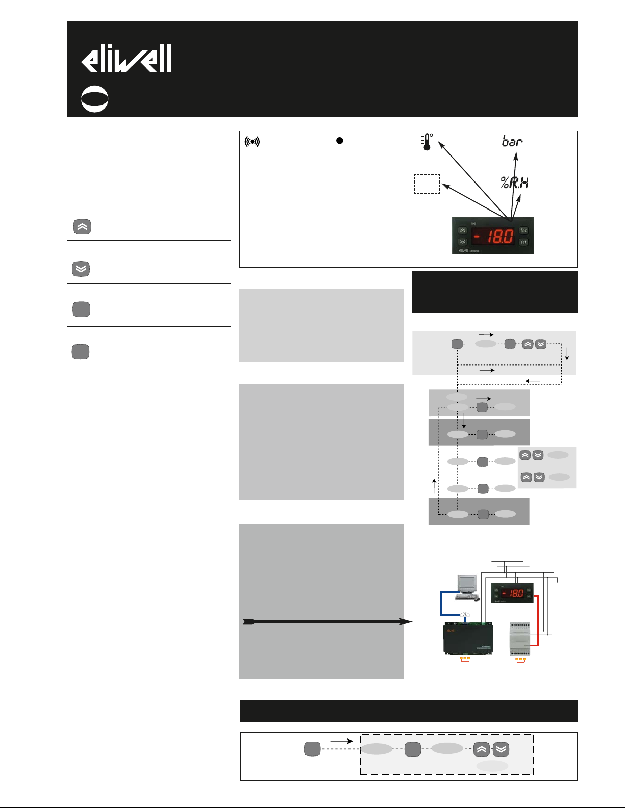
The user has a display and four buttons
for controlling instrument status and programming.
BUTTONS AND MENUS ACCESSING
AND USING MENUS
The resources are arranged in a menu that
can be accessed by pressing and quickly
releasing the “set” button (Machine Status
menu) or holding down the “set” button
for more than 5 seconds (Programming
menu). To access the contents of each
folder indicated by the relevant label, just
press the “set” button once. You can now
scroll through the contents of each folder,
modify it or use its functions. If you do
not use the keyboard for over 15 seconds
(time-out) or if you press the “fnc” button
once, the last value shown on the display
is confirmed and you return to the previous screen mask.
MACHINE STATUS MENU
(See Machine Status Menu Diagram)
To access the Machine Status menu, press
the “set” button and quickly release it
(The “SP1” label appears.
V/I
V/I
MODELS
MODELS
ONL
ONLY)Y)
(If alarms are active, with the exception of
faulty probes/probe errors, the “AL” label
appears). By using the “UP” and “DOWN”
buttons you can scroll through the other
folders in the menu: the folders are indicated below in the order they appear:
-AL: alarm folder
LXLXMODELS
MODELS
ONL
ONLYY
NOTE: The AL folder appears if high or
low temperature alarms are present.
Alarm (IF PRESENT)
•ON for active alarm;
•blinking for silenced
alarm that is still present
LLEEDDSS AANNDD
KKEEYYPPAADD
decimal point:
associated with displaying
decimal point
•ON if enabled-decimal
point present (see ndt
parameter);
•OFF if disabled-decimal
point NOT present (see
ndt parameter);
for NTC/PTC
or Pt100-TC
input
for V/I input
(current-
voltage std
signals)
bar for
V/I input
(pressure)
%RH for
V/I input
(humidity)
EM300(LX)
electronic digital indicator
code 9IS43049
rel. 6/06
GB
UP Button Scrolls through the menu items
Increases the values
DOWN button Scrolls through the menu items
Decreases the values
fnc button ESC function (quit)
Set point button 1-Accesses Machine Status Menu
(ACTIVE ALARMS, PROBE READING) and related labels/values;
1-Accesses Programming Menu
(PARAMETERS, COPY C ARD (LX
models)) and related labels/values;
3-Confirms commands
fnc
set
ALARM PRESENT?
If an alarm condition exists when the
“Machine Status” menu is accessed, the
“AL” folder label appears with the alarm
codes. (see section on “Diagnostics”).
if alarm(s)
present
AL
set
alarms
set
scroll alarms
press and release
(single press)
MACHINE STATUS MENU DIAGRAM
HOW TO LOCK THE KEYBOARD
Keyboard operating can be locked by programming the “Loc” parameter (see folder
with “diS” table). If the keyboard is locked
you can only access the Programming
MENU (see) Functions CANNOT be activated with buttons (to silence alarms, for
example).
TELEVIS SYSTEM (LX MODELS ONLY)
The Televis remote control systems can be
connected using the TTL serial port.
The TTL- RS 485 interface module must be
used:
• 130 or 150 BUS ADAPTER.
• 350 BUS ADAPTER for EM300(LX) with
V/I. Pt100/TC input.
To configure the instrument to do this, you
need to access the folder with the “Add”
label and use the “dEA” and “FAA” parameters.
ONLY MODELS LX
AL
Add
dIS
CnF
set
level 1 par
level 1 par
level 1 par
level 1 par
set
set
set
set
PA1≠0
set
set PA1 value
Fpr
level 1 par
set
level 1
change
par value
scroll
parameters
press for 5 sec
ONLY MODELS LX
ONLY MODELS LX
rE1
input VI
PROGRAMMING MENU
DIAGRAM
230V
PC with
Televis package
N
L
only use 350 Bus Adapter for model with V/I,
Pt100/TC input
Page 2
EM300(LX) 2/6
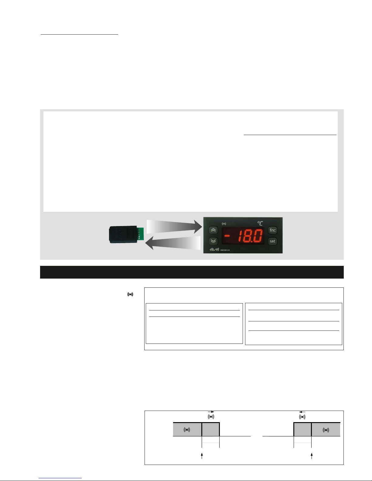
USING COPY CARD (LX MODELS ONLY)
The Copy Card is an accessory connected to
the TTL serial port used for quick programming
of the unit parameters (upload and download
parameter map to one or more units of the
same type). Operations are described below:
Fr-Format
This command is used to format the copy card.
This is necessary if
•it is used for the first time,
•it is used with models that are incompatible,
•after use with a specific model, another model
must be connected.
Warning: when the copy card has been programmed
using the “Fr” parameter all the data entered is cancelled. This operation cannot be undone.
UL-Upload
This operation unloads the programming parameters from the instrument.
dL-Download
This operation downloads the programming
parameters to the instrument.
NOTE:
• UPLOAD: instrument —> Copy Card
• DOWNLOAD: Copy Card —> instrument.
The operations are performed by accessing the
folder identified by the “FPr” label and selecting
the “UL”, “dL” or “Fr” commands. The operation
is confirmed by pressing the “set” button. If the
operation is successful, a “y” is displayed whereas if it is unsuccessful an “n” will be displayed.
Download “from reset”
Connect the copy card with the instrument OFF.
When the instrument is switched on the programming parameters will be downloaded into
the copy card; when the lamp test has been
completed, the following appear on the display
for about 5 seconds:
• label dLY if copy operation is successful
• label DLn if operation fails
PLEASE NOTE:
• after downloading the instrument will work
with the parameter map settings that have just
been downloaded.
PROGRAMMING MENU
(See Programming Menu Diagram)
1) Displaying level 1 parameters
To access the Programming menu, hold
the “set” button for more than 5 seconds.
Level 1 parameters can be protected by a
PASSWORD* (defined by parameter
DIS/PA1) If the PASSWORD is enabled, the
label “PA1” will appear when you access
the Programming Menu; press the “set”
button and the value “0” will appear; enter
the password using the “UP”/”DOWN” buttons and press the “set” button again. This
allows you to access the level 1 parameters. Use the “UP” and “DOWN” buttons
to scroll through the other folders; the
folders will only display level 1 parameters.
PLEASE NOTE: It is strongly recommended
that the unit is switched off and on again
each time parameter configuration is
changed in order to prevent malfunctioning of the configuration and/or ongoing
timings (compulsory for selection of
probe type and count parameters).
*PASSWORD
The “PA1” password allows level 1 and
level 2 parameters to be accessed. This
password is not present in the standard
configuration. To enable it (value ≠0) and
assign it the desired value, access the
Programming menu in the “diS” folder.
If the password is enabled, it will be
requested when entering the
“Programming” menu.
The alarm condition is always signalled by a
buzzer (if present) and the alarm icon LED
(IF PRESENT)
The alarm signal from the
• control probe that measures values outside
the nominal reading range
• control probe faulty/shorted/open probe for
4…20 mA* model appears directly on the instrument display as E1. Note: to prevent false
alarms, the error condition must persist for
more than 10 seconds.
An error condition in probe 1 (regulation) leads
to:
• E1 code appearing on display
PLEASE NOTE: In case of wrong connection of
the 3rd wire (Pt100 sensor) in “AL” folder it will
appear the label “Pt3”.
For few seconds the display will shows a uncorrect temperature.
MAXIMUM AND MINIMUM TEMPERATURE
ALARM
If an alarm condition occurs and alarm exclusion times are not in progress (see alarm exclusion parameters), the fixed alarm icon comes
on.
DIAGNOSTICS
DISPLAY
E1
*faulty/shorted/open probe for 4…20 mA model;
the other probes, if shorted, will measure the 0V or
0mA value)
FAULT
Probe 1 (control) faulty*
Table of faulty probes
DISPLAY
AH1
AL1
Press any button to silence the alarm. The LED will
start to blink.
ALARM
High temperature alarm (referring to
thermostat control probe or probe 1)
Low temperature alarm (referring to
thermostat control probe or probe 1)
Alarm table
Alarms are considered as absolute values This alarm
condition can be viewed in the “AL” folder with labels
“AH1-AL1”.
The maximum temperature alarm occurs when the
probe temperature is:
•higher than or equal to HAL/HA1
The minimum temperature alarm occurs when the
probe temperature is lower than or equal to LAL/LA1
The maximum temperature alarm back swing occurs
when the probe temperature is:
• higher than or equal to HAL/HA1 - AFd
Minimum temperature alarm back swing occurs when
the probe temperature is:
•higher than or equal to LAL/LA1 + AFd
LAL/LA1
AFd
HAL/HA1
AFd
Max/Min. Alarm
Diagram (minimum
and maximum
temperature)
UPLOAD
DOWNLOAD
Page 3
EM300(LX) 3/6
GENERAL TECHNICAL
DATA
Front protection: IP65. Casing: PC+ABS
UL94 V-0 resin plastic body, polycarbonate
front, thermoplastic resin buttons.
Dimensions: front panel 74x32 mm,
•depth 30 mm (terminals excluded)
•’switching models’: depth 60 mm (terminals excluded)
Mounting: on panel, with drilling template
71x29 mm (+0.2/-0.1 mm).
Operating temperature: -5…55 °C.
Storage temperature: -30…85 °C.
Usage ambient humidity: 10…90 % RH
(non-condensing).
Storage ambient humidity: 10…90% RH
(non-condensing).
Buzzer output: only in certain models.
(LX MODELS ONLY)
Serial: TTL for connection to
•Copy Card;
•TelevisSystem.
Consumption:
• 230V model: 1,8 W max.;
• 12V model: 0.5 W max.
• ‘switching’ models: 3 W max.
Power supply:
• 230Va ±10% 50/60 Hz or
• 12Va/c ±10% 50/60 Hz or
• 12-24Va ±10%, 12-36Vc ±10% SELV
(only models NTC/PTC & Pt100-TC)
Warning: check the power supply specified
on the instrument label: contact the Sales
Office for further information
EM300(LX) TECHNICAL DATA
WITH PTC/NTC INPUT
Display range:
• NTC probe: –50.0…110.0°C (–58…230°F);
• PTC probe: –55.0…140.0°C (–67…284°F)
on display 3 1/2 digits + sign.
Analogue input: one PTC or NTC input
(parameter-selectable).
Measurement range: from -55 a 140 °C.
Accuracy: better than 0.5% of bottom scale
+ 1 digit.
Resolution: 0.1°C (0.1°F up to +199.9°F;
1°F above).
WITH V INPUT - I INPUT
Display range:
-99…100 (ndt = n), -99.9…100.0 (ndt = y),
-999…1000 (ndt = int) on display 3 1/2
digits + sign.
Analogue input (see table):
• V input (0-1V, 0-5V, 0-10V) or
• I input (0…20mA, 4…20mA);
Measurement range: from –999 to 1000.
Accuracy: better than 0.5% of bottom scale
+ 1 digit.
Resolution: 1 or 0.1 digits depending on
parameter settings.
Current input impedance: 100 ohm
Voltage input impedance: 20K ohm
NOTE: for 3-wire sensor connections the
maximum current supplied by the device
is 25mA (measurement + sensor power
supply)
WITH PT100-TC INPUT
Viewing range:
• Pt100 model : -200…800°C
(-328...1472°F),
• TcJ model -40…760°C (-40...1400°F),
•TcK model -40…1350°C (-40...2462°F)**
** (-40..1999°F) above which SuP is
displayed, with decimal point, selectable
through parameter ndt
on 3 digit &
1
/2+ mark display.
Analogue input: one PT100 input or TcJ or
TcK depending on model.
Measuring range: from -200 to 1999.
Accuracy:
• Pt100 model : 0,5% for all scale + 1 digit;
0,2% from -150 to 300°C.
• TcJ model: 0,4% for all scale + 1 digit;
• TcK model 0,5% for all scale + 1 digit;
0,3% from -40 to 800°C.
Resolution:
• Pt100 model: 0,1°C (0,1°F) within 199,9
°C, 1°C (1°F) over
• TcJ/TcK model 1°C (1°F).
Power supply: 12/24 Va/c ±10% or 230Va
±10% 50/60 Hz.
NOTE: in model Pt100 the thermal drift
in the -5...55°C range can reach 3°C.
ELECTRICAL
WIRING
Warning! Always switch off machine
before working on electrical connections.
The instrument has screw terminals for
connecting electrical cables with a diameter of 2,5 mm
2
max. (only one conductor
per terminal for power connections). for
terminal capacity, see the label on the
instrument. Make sure that the power
voltage complies with the device voltage.
Probe cables, power supply cables and the
TTL serial cable should be kept separate
from power cables.
The sensor can be extended using an ordinary bipolar cable (note that extending
the probe may affect the electromagnetic
compatibility (EMC) of the instrument:
special care must be used when wiring).
• version with PTC/NTC input:
The sensor has no connection polarity.
• version with V/I/Pt100-TC input:
NOTE: Check the probe connection
polarity.
NOTE: The technical characteristics in
this document concerning measurements (range, accuracy, resolution, etc.)
refer to the instrument in the strictest
sense and not to any accessories provided such as probes, for example.
This means that an error introduced by
the probe is added to any error that is
in the instrument.
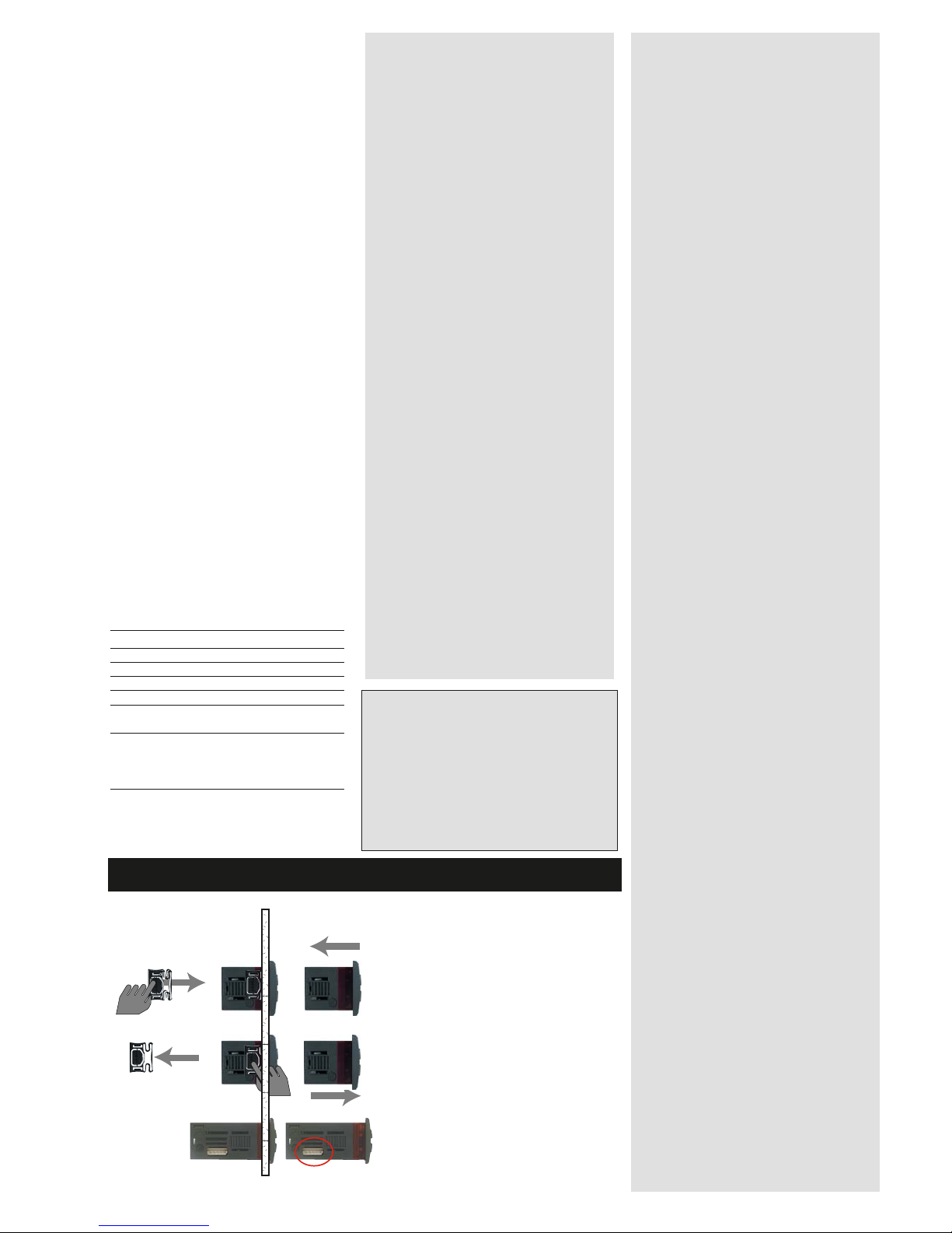
The unit has been designed to be
panel-mounted: Drill a 29x71 mm
hole, insert the keyboard and fix it
in place with the special brackets
provided. Do not assemble the keyboard in excessively dirty and/or
dirty locations because it is
designed to be used in locations
with normal pollution levels. Always
make sure that the area next to the
unit cooling slits is adequately ventilated.
switching
models
only TTL models
MECHANICAL ASSEMBLY AND CUT-OUT
Model
EM300(LX)
EM300(LX)
EM300(LX)
EM300(LX)
EM300(LX)
EM300(LX)
NOTE: For TECHNICAL DATA and connections
using EWPA and EWHS probes refer to the
relevant technical data sheets and/or diagram
on last page.
* external power supply.
For external power supply characteristics, see
characteristics of connected sensor.
Analogue input
NTC-PTC probe
Pt100-TcK-TcJ probe
EWPA 007/030
EWHS 280/300/310*
0…1/5/10 V voltage input
0/4…20mA current input
Analogue input table
Page 4

PARAMETER
AFd
HAL (!)
LAL (!)
PAO (!)
tAO
tP
dEA (!)
FAA (!)
LOC
PA1
ndt
CA1
LdL
HdL
dro(*)
H00 (!)
rEL
tAb
UL
dL
Fr
* DEFAULT column: for these parameters the default depends on the model.
** VALUE column: to be compiled manually with any custom settings (if different from default value).
EM300(LX) 4/6
PARAMETER TABLE FOR EM300(LX) with NTC/PTC probe
DESCRIPTION
ALARMS (folder with “AL” label)LXLX
MODELS
MODELS
ONL
ONLYY
Alarm Fan differential. Alarm differential.
Higher ALarm. Maximum temperature alarm. Temperature value
(considered as absolute value) which if gone above triggers the
alarm signal.
Lower ALarm. Minimum temperature alarm. Temperature value
(considered as absolute value) which if gone below triggers the
alarm signal.
Power-on Alarm Override. Alarm exclusion time after instrument
start-up, after a power failure.
Temperature Alarm Override. Temperature alarm signal delay
time.
silences alarm with button
COMMUNICATION (folder with “Add” label) LX MODELS
ONLY
DEA= device number within the family (valid values: from 0 to 14)
FAA= device family (valid values: from 0 to 14)
The value couple FAA and dEA represents the network address of
the device and it is indicated in the following way: "FF.DD" (where
FF=FAA and DD=dEA).
DISPLAY (folder with “diS” label)
Keyboard locked (set point and buttons). However, you can still
access the parameter programming menu and modify parameters
including the status of this parameter to allow keyboard unlocking. y = yes; n = no.
Password 1. When enabled (value is not 0) it represents the access
key to level 1 parameters.
number display type. Display with decimal point. y = yes; n = no,
int= whole numbers.
Calibration 1. Positive or negative temperature value that is added
to the value read by control probe (analogue input) before being
displayed or used for regulation.
Minimum value that can be displayed.
Maximum value that can be displayed. Select °C or °F to display
temperature read by probe. N. B.: when changing from °C to °F
or vice versa the temperature values are NOT converted
(e.g. 10°C becomes 10°F)
CONFIGURATION (folder with “CnF” label)
Selection of input type, PTC/NTC
Device version. Read only parameter.
Reserved. Read only parameter.
COPY CARD (folder with “Fpr” label) LXLX
MODELS
MODELS
ONL
ONLYY
UpLoad: transfer of programming parameters from instrument to
Copy Card.
downLoad: transfer of programming parameters from Copy Card
to instrument.
Format. Cancels all data entered in the copy card.
N.B.: if “Fr” parameter (formatting of copy card ) is used the
data entered in the card will be permanently lost. This operation cannot be undone. After the operation with the Copy
Card the device must be switched off and then switched
back on
DEFAULT*
2.0
50.0
-50.0
0
0
y
0
0
n
0
n
0
-50.0 (-200 (§))
140.0 (1500 (§))
0
*
/
/
/
/
/
RANGE
1.0...50.0
LAL...150.0
-50.0...HAL
0...10
0...250
n/y
0…14
0…14
n/y
0...250
n/y
-12.0...12.0
(-30,0...30,0) (§)
-55.0…HdL (-328,0...HdL) (§)
LdL…302 (LdL...1999) (§)
0/1
0/1
/
/
/
/
/
VALUE**
U.M.
°C/°F
°C/°F
°C/°F
hours
min
flag
num
num
flag
num
flag
C/°F
C/°F
C/°F
flag
flag
/
/
/
/
/
LX
LX
MODELS
MODELS
ONL
ONL
Y
Y
LX
LX
MODELS
MODELS
ONL
ONL
Y
Y
LX
LX
MODELS
MODELS
ONL
ONL
Y
Y
RESPONSIBILITY AND RESIDUAL RISKS
Eliwell & Controlli s.r.l. shall not be liable for any dam-
ages deriving from:
- installation/use other than that prescribed and, in particular, which does not comply with the safety standards
specified in the regulations and/or those given herein;
- use on equipment that does not guarantee adequate
protection against electric shock, water or dust when
assembled.
- use on equipment that allows dangerous parts to be
accessed without the use of tools;
- tampering with and/or alteration of the product;
- use on equipment that does not comply with the standards and regulations in force.
DISCLAIMER
This document is exclusive property of Eliwell &
Controlli s.r.l. and cannot be reproduced and circulated unless expressly authorized by Eliwell & Controlli
s.r.l..
Although Eliwell & Controlli s.r.l. has taken all possible
measures to guarantee the accuracy of this document,
it declines any responsibility for any damage arising
out of its use.
The same applies to any person or company involved
in preparing and writing this manual. Eliwell &
Controlli s.r.l. reserves the right to make any changes
or improvements without prior notice and at any time.
CONDITIONS OF USE
PERMITTED USE
For safety reasons the instrument must be installed and used in accordance with the
instructions supplied. Users must not be able to access parts with dangerous voltage
levels under normal operating conditions.
The device must be protected from water and dust depending on the specific application and only be accessible by using special tools. (except for the front panel).
The device is ideally suited for use on household appliances and/or similar refrigeration equipment and has been tested with regard to safety in accordance with the
European harmonized reference standards.
It is classified as follows:
Installation: Class II where applicable (front keypad)
Protection class: 2
Material group: IIIa
Device status: Permanently connected fixed device.
Measurement category: III
UNPERMITTED USE
The use of the unit for applications other than those described above is forbidden.
(°) The mathematical conversion for temperature
is °F=(9/5)* °C+32. For example: 32°F=0°C;
50°F=10°C. dro parameter: when changing from °C
to °F or vice versa the mathematical conversion is
NOT performed and the values are NOT modified.
All the temperature values set will therefore need
reviewing. e.g. with a set point set at 10°C, when
changing the value to °F the set point will become
10°F and not 50°F (according to conversion table)
(§) Pt100/TC model
Page 5
EM300(LX) 5/6
PARAMETER
HA1 (!)
LA1 (!)
AFd
PAO (!)
tAO
tP
H00 (!)
H03
H04
rEL
tAb
* DEFAULT column: for these parameters the default depends
on the model.
(!) CAUTION!
• If one or more parameters marked with (!) are modified, the device must be switched off after the modification and then switched back on
•PLEASE NOTE: We strongly recommend that you switch the instrument off and on again each time parameter configuration is changed in order to prevent malfunctioning of the configuration and/or ongoing timings.
DESCRIPTION
ALARMS (folder with “rE1” label)LXLX
MODELS
MODELS
ONL
ONLYY
Higher ALarm. Maximum temperature alarm. Temperature value
(considered as absolute value) which if gone above triggers the alarm
signal.
Lower ALarm. Minimum temperature alarm. Temperature value
(considered as absolute value) which if gone below triggers the alarm
signal.
ALARMS (folder with “AL” label) LXLX
MODELS
MODELS
ONL
ONLYY
Alarm Fan differential. Alarm differential.
Power-on Alarm Override. Alarm exclusion time after instrument
start-up, after a power failure.
Temperature Alarm Override. Temperature alarm signal delay
time.
silences alarm using button
COMMUNICATION (folder with “Add” label) LX MODELS ONLY
SEE
SEE
EM300
EM300 TT
ABLE above DISPLA
ABLE above DISPLA
Y (folder with “
Y (folder with “
diS” label)
diS” label)
SEE
SEE
EM300
EM300 TT
ABLE above
ABLE above
V/I
V/I
MODELS
MODELS
ONL
ONLY:Y:
NOTE 1: ndt parameter has range n/y/int int=whole numbers.
NOTE 2: LdL has range -99...HdL or -99.9...HdL or -999...HdL
according to ndt parameter setting HdL has range -LdL...100 or
-LdL...100.0 or -LdL...1000 according to ndt parameter setting
CONFIGURA
CONFIGURA
TION (folder with “CnF” label)
TION (folder with “CnF” label)
Selection of probe type
Minimum value of voltage / current input
Maximum value of voltage / current input
Device version. Read only parameter.
Reserved. Read only parameter.
COPY CARD (folder with “Fpr” label) LXLX
MODELS
MODELS
ONL
ONLYY
SEE EM300 TABLE above
DEFAULT*
*
(§) 1200
*
(§) -200
2.0
0
0
y
(§) 2
*
*
/
/
RRAANNGGEE ((VV//II))
LA1...150.0
-50.0...HA1
1.0...50.0
0...10
0...250
n/y
NOTE 3:
NOTE 3:
the dro parameter is
the dro parameter is
not present
not present
§§§
-99.0…100.0
(ndt= y)
-999…1000
(ndt= int)
as above
/
/
VALUE**
U.M.
°C/°F
°C/°F
°C/°F
hours
min
flag
num
C/°F
C/°F
/
/
PARAMETER TABLE FOR EM300(LX) with V/I & Pt100-TC input
LX
LX
MODELS
MODELS
ONL
ONL
Y
Y
LXLXMODELS
MODELS
ONL
ONLYY
LXLXMODELS
MODELS
ONL
ONLYY
§§§
010/05/01 for VOLTAGE INPUT
420/020 for CURRENT INPUT
(§) Pt100/TC model
RRAANNGGEE ((PPtt110000))
LA1...1999
-328...HA1
1.0...50.0
0...10
0...250
n/y
NOTE 3:
NOTE 3:
the dro
the dro
parameter is
parameter is
present
present
(§) Jtc/HtC/Pt1
not present
not present
/
/
Page 6
EM300(LX) 6/6
Supply
1,8 W max
3 4 5
+-
+12V
V
3 4
Pb1
NTC/PTC
V
1 2
3 4 5
A
Supply
0.5 W max
EM300(LX) - 12V & 230V
LX models ONLY
Pt100-TC
3 4 5
+
-
(230V model)
(12V model)
3 4 5
+-
+12V
I
I
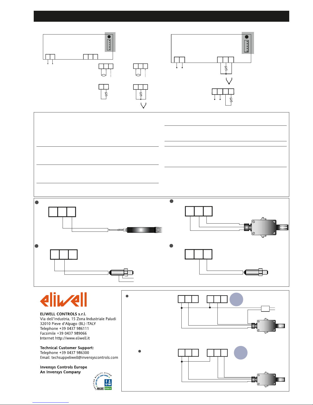
WIRING DIAGRAMS
6/2006 - GB cod. 9IS43049
TERMINALS
1 - 2 Power supply
• 230Va ±10% 50/60 Hz or
• 12Va/c ±10% 50/60 Hz or
• 12-24Va ±10%, 12-36Vc ±10% SELV (only models
NTC/PTC & Pt100-TC)
NTC/PTC Models
3 - 4 Pb1 probe input
V Models
3 - 4 - 5 Voltage input (3=GND; 4=signal; 5=+12V)*
I Models
3 - 4 - 5 Current input (3=GND; 4=signal; 5=+12V)*
Pt100-TC Models
4 - 5 TcJ-TcK Input
3 - 4 - 5 Pt100 3 wires Input
LX MODELS ONLY
A TTL input for Copy Card and connection to
TelevisSystem
* according to model
* Check probe connection polarity.
EWHS 300/310 3 wires Power Supply from EM300(LX)
Probe
EWHS 280 2 wires Power Supply from EM300(LX)
Probe
EWPA 007/030 2 wires External Power Supply for Transducer
Transducer
brown
blue
brown
white
GND (only EWHS310)
V+
Power Supply
for Transducer
RH/T
3 4 5
3 4 5
3 4 5
EWPA 007/030 2 wires Power Supply from EM300(LX)
Transducer
brown
white
3 4 5
EWHS 310 HUMID. + TEMP.
Power Supply from external Power Supply
GND
V+
RH
3 4 5
3 4 5
T
230V
GND
GND IN V+
GND IN V+
EWHS 310 HUMID. + TEMP.
Power Supply from EM300(LX)
GND
V+
RH
3 4 5
3 4 5
T
GND
GND IN V+
GND IN V+
EWHS 310
EWHS 310
3 4
Pb1
NTC/PTC
1 2
3 4 5
A
Supply
3 W max
EM300(LX) - 12-24Va
12-36Vc
LX models ONLY
Pt100-TC
+
-
1 2
Supply
3 W max
EM300 current
EM300 current
 Loading...