

Page 1
ECH 200BD "Adaptive"
Electronic Controller for mono and bicompressor Chillers with Adaptive
Algorithm
<IMG INFO>
396,8
Page 2

1 SUMMARY
1 Summary................................................................................................................................................................... 2
2 How to use this manual ........................................................................................................................................ 5
3 Introduction ............................................................................................................................................................. 6
3.1 Models available............................................................................................................................................................................... 6
4 Installation ............................................................................................................................................................... 8
4.1 Connection diagrams ...................................................................................................................................................................... 8
4.2 Configuration of analogue inputs ................................................................................................................................................ 9
4.3 Configuration of digital inputs.................................................................................................................................................... 10
4.4 Configuration of outputs.............................................................................................................................................................. 10
4.4.1 Relays................................................................................................................................................................................................................................................... 11
4.4.2 Triac ..................................................................................................................................................................................................................................................... 11
4.4.3 Alarm...................................................................................................................................................................................................................................................12
4.4.4 Fan module pilot output ................................................................................................................................................................................................................12
4.4.5 Optional output ................................................................................................................................................................................................................................ 12
4.4.6 Remote keyboard output ............................................................................................................................................................................................................... 12
4.5 Physical quantities and units of measurement........................................................................................................................ 13
4.5.1 Temperature- or pressure-based operation............................................................................................................................................................................... 13
4.5.2 Units of measurement.....................................................................................................................................................................................................................13
4.6 Serial outputs ..................................................................................................................................................................................14
4.6.1 Copy card device...............................................................................................................................................................................................................................14
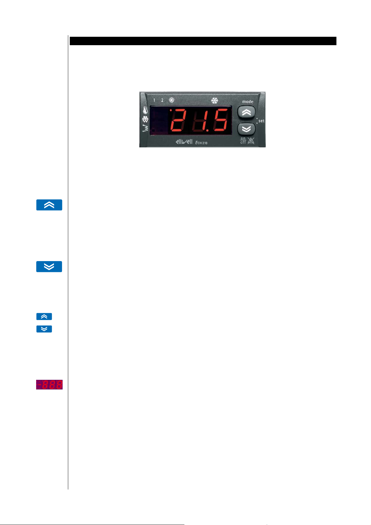
5 User interface......................................................................................................................................................... 15
5.1 Keys.................................................................................................................................................................................................... 15
5.2 Displays.............................................................................................................................................................................................15
5.2.1 Display.................................................................................................................................................................................................................................................15
5.2.2 SET display for air-air machines (for models Ech 2xxB only) ................................................................................................................................................ 15
5.2.3 Led ........................................................................................................................................................................................................................................................ 16
5.3 Remote keyboard............................................................................................................................................................................ 16
5.4 Parameter programming – Menu levels ...................................................................................................................................18
5.4.1 Visibility of parameters and sub-menus .....................................................................................................................................................................................20
6 System configuration........................................................................................................................................... 21
6.1 Compressors..................................................................................................................................................................................... 21
6.1.1 Compressor configuration..............................................................................................................................................................................................................21
6.1.2 Compressor on/off sequence .........................................................................................................................................................................................................21
6.1.3 Compressor timing ........................................................................................................................................................................................................................... 21
6.2 Condensation fan ........................................................................................................................................................................... 22
6.2.1 Fan configuration ............................................................................................................................................................................................................................. 22
6.2.2 DRV module ....................................................................................................................................................................................................................................... 23
6.3 Reversing valve................................................................................................................................................................................23
6.4 Hydraulic pump ..............................................................................................................................................................................23
6.5 Internal anti-freeze/supplementary electrical heaters ..........................................................................................................24
6.5.1 Supplementary electrical heaters................................................................................................................................................................................................. 25
6.6 External anti-freeze electrical heaters .......................................................................................................................................25
6.7 Boiler .................................................................................................................................................................................................25
7 Adaptive .................................................................................................................................................................. 26
7.1 Adaptive function........................................................................................................................................................................... 26
7.1.1 Adaptive function: regulator ......................................................................................................................................................................................................... 26
7.1.2 Set point offset (for ET<MT) .......................................................................................................................................................................................................... 26
7.1.3 Set point regression (for ET≥MT) ................................................................................................................................................................................................ 27
7.1.4 Protection in Cooling mode........................................................................................................................................................................................................... 28
7.1.5 Protection in Heating mode ..........................................................................................................................................................................................................28
7.1.6 Notes.................................................................................................................................................................................................................................................... 28
7.1.7 Example .............................................................................................................................................................................................................................................. 28
7.2 Fan control in Defrosting mode .................................................................................................................................................. 29
7.3 Antifreeze function for units with heat pump.......................................................................................................................... 29
8 Temperature control functions .........................................................................................................................30
8.1 Selection of operating mode from analogue input................................................................................................................30
8.2 Setting set points ............................................................................................................................................................................ 31
Page 3

8.3
Dynamic set point ..........................................................................................................................................................................31
8.4 Switching from digital input........................................................................................................................................................ 33
8.5 Load control..................................................................................................................................................................................... 33
8.5.1 Compressor control – regulation algorithm.............................................................................................................................................................................. 33
8.5.2 Condensation fan control .............................................................................................................................................................................................................. 34
8.5.3 Reversing valve control ...................................................................................................................................................................................................................36
8.5.4 Hydraulic pump control.................................................................................................................................................................................................................. 36
8.5.5 Anti-freeze/supplementary electrical heater control .............................................................................................................................................................. 36
8.5.6 External anti-freeze electrical heater control............................................................................................................................................................................ 37
8.5.7 Supplementary electrical heater control.................................................................................................................................................................................... 37
8.5.8 Boiler control ..................................................................................................................................................................................................................................... 37
9 Functions.................................................................................................................................................................38
9.1 Recording hours of operation......................................................................................................................................................38
9.2 Defrosting.........................................................................................................................................................................................38
9.2.1 Defrost start .......................................................................................................................................................................................................................................38
9.2.2 Defrost end ......................................................................................................................................................................................................................................... 39
9.2.3 Counter mode.................................................................................................................................................................................................................................... 39
9.2.4 Start defrost temperature compensation...................................................................................................................................................................................39
9.3 Power failure.................................................................................................................................................................................... 40
10 Diagnostics ............................................................................................................................................................. 41
10.1 List of alarms ................................................................................................................................................................................... 41
10.1.1 TABLE OF DIGITAL ALARMS: .................................................................................................................................................................................................... 45
10.1.2 TABLE OF ANALOGUE ALARMS: ............................................................................................................................................................................................. 45
11 Parameters .............................................................................................................................................................46
11.1 Description of parameters............................................................................................................................................................ 46
11.1.1 Configuration parameters ........................................................................................................................................................................................................46
11.1.2 Compressor parameters (CP) ................................................................................................................................................................................................... 48
11.1.3 Fan control parameters (FAN) ................................................................................................................................................................................................ 48
11.1.4 Alarm parameters (ALL)............................................................................................................................................................................................................ 49
11.1.5 Anti-freeze/boiler parameters (FRO)......................................................................................................................................................................................50
11.1.6 Defrost parameters (DFR)......................................................................................................................................................................................................... 51
11.2 Table of parameters....................................................................................................................................................................... 51
12 Technical features................................................................................................................................................. 55
12.1 Technical information...................................................................................................................................................................55
12.2 Electromagnetic characteristic.................................................................................................................................................... 55
12.3 Dimensions.......................................................................................................................................................................................55
12.4 Regulations ...................................................................................................................................................................................... 55
13 Use of the device ................................................................................................................................................... 57
13.1 Permitted use................................................................................................................................................................................... 57
13.2 Forbidden use .................................................................................................................................................................................. 57
14 Responsibility and residual risks........................................................................................................................ 58
15 Disclaimer ...............................................................................................................................................................59
16 Examples of air conditioning circuits............................................................................................................... 60
16.1 Air-water chiller 1 compressor ....................................................................................................................................................60
16.2 Air-water chiller 2 compressor ....................................................................................................................................................61
16.3 Water-water Chiller 1 compressor.............................................................................................................................................. 62
16.4 Water-water Chiller 2 compressor.............................................................................................................................................. 63
16.5 Air-water heat pump 1 compressor ........................................................................................................................................... 64
16.6 Air-water heat pump 2 compressors.......................................................................................................................................... 65
16.7 Water-water heat pump 1 compressor ..................................................................................................................................... 66
16.8 Water-water heat pump 2 compressors.................................................................................................................................... 67
17 Glossary ...................................................................................................................................................................68
18 Appendix .................................................................................................................................................................68
18.1 CF Modules ......................................................................................................................................................................................70
18.1.1 CF modules: technical data......................................................................................................................................................................................................70
18.1.2 CF modules: connections .......................................................................................................................................................................................................... 70
18.1.3 CF modules: mechanical assembly......................................................................................................................................................................................... 71
ECH 200 BD
3/76
Page 4

18.2
Copy Card......................................................................................................................................................................................... 72
18.3 EMC filter..........................................................................................................................................................................................72
18.4 Param Manager.............................................................................................................................................................................. 72
18.4.1 PCInterface interface module ..................................................................................................................................................................................................73
18.5 Sonde................................................................................................................................................................................................. 73
ECH 200 BD
4/76
Page 5

References
Cross references
Icons for emphasis
2 HOW TO USE THIS MANUAL
This manual is designed to permit quick, easy reference with the following features:
References column:
A column to the left of the text contains references to subjects discussed in the text to help you locate the information you
need quickly and easily.
Cross references:
All words written in italics are referenced in the subject index to help you find the page containing details on this subject;
supposing you read the following text:
”when the alarm is triggered, the compressors will be shut down”
The italics mean that you will find a reference to the page on the topic of compressors listed under the item compressors
in the index.
If you are consulting the manual “on-line” (using a computer), words which appear in italics are hyperlinks: just click on a
word in italics with the mouse to go directly to the part of the manual that discusses this topic.
Some segments of text are marked by icons appearing in the references column with the meanings specified below:
Take note: information on the topic under discussion which the user ought to keep in mind
Tip: a recommendation which may help the user to understand and make use of the information supplied on the topic
under discussion.
Warning! : information which is essential for preventing negative consequences for the system or a hazard to
personnel, instruments, data, etc., and which users MUST read with care.
Page 6
Ech 200 Family
3 INTRODUCTION
Ech 200 is a compact device that permits control of air conditioning units of the following types:
• air-air
• air-water
• water-water
• condensing units
single-circuit, with 1 or 2 compressors (steps).
It is possible to control condensation fan speed proportionately for currents of up to 2 A without using external devices.
Main characteristics:
• Temperature control based on inlet or outlet probe, depending on the type of machine and its configuration
• Condensation control
• Input may be configured for an NTC temperature probe or for a 4...20 mA signal (through parameters)
• Automatic change-over
• Boiler or supplementary electrical heater control for heating
• Internal fan control up to 3 steps in the air-air application
• Dynamic set point
• Parameter setting from the keyboard or through a personal computer
• Copy card for uploading and downloading parameter maps
• Remote keyboard (up to 100 m) which may be connected up directly without a serial interface
• 4-20 mA or 0-10 V output (optional internal card)
• User interface with a menu featuring 2 different levels of access through password management
• Interface menu may be fully configured from a PC.
3.1 Models available
The ECH 200 family’s models (base, keyboard and expansion) and a reference tabel containing the base parameters are
illustrated below:
E
CH 200
Models available
Base
ECH210 BD
ECH210 BD
Expansion EXP200 is available for only model Ech 211.
Tastiera
EKW200
EW/S200
Espansione
EXP200
Page 7

Base parameters
tabel
Model ECH 210 BD ECH 215 BD
Circuits 1 1
Application
Input/output
Features
Diagnostic
Compressors (in chiller) 2 2
Compressors (in heat pump) 1 2
Stages 1 1
Relays (2A 230 V~) 4 5
Triac (2A 230 V~) 1
Digital input 5 5
Analog output
Analog input 4 4
Srew connectors • •
Remote keyboard • •
Remote on-off • •
Heat pump control • •
Defrost • •
Condensing pressure control • •
Water pump control • •
Electric heater • •
Dynamic set point • •
Water free cooling • •
Water flow alarm • •
High pressure alarm • •
Low pressure alarm • •
Thermal compressor alarm • •
Thermal fan alarm • •
Antifreeze alarm • •
High water temperature alarm • •
ECH 200 BD
7/76
Page 8
Connection to
probe AI3
configured as NTC
4 INSTALLATION
Before proceeding with any operation, first make sure that you have connected up the power supply to the
device through an appropriate external current transformer. Always follow these rules when connecting boards to
one another and to the application:
• Never apply loads which exceed the limits set forth in these specifications to outputs;
• Always comply with connection diagrams when connecting up loads;
• To prevent electrical couplings, always wire low voltage loads separately from high voltage loads;
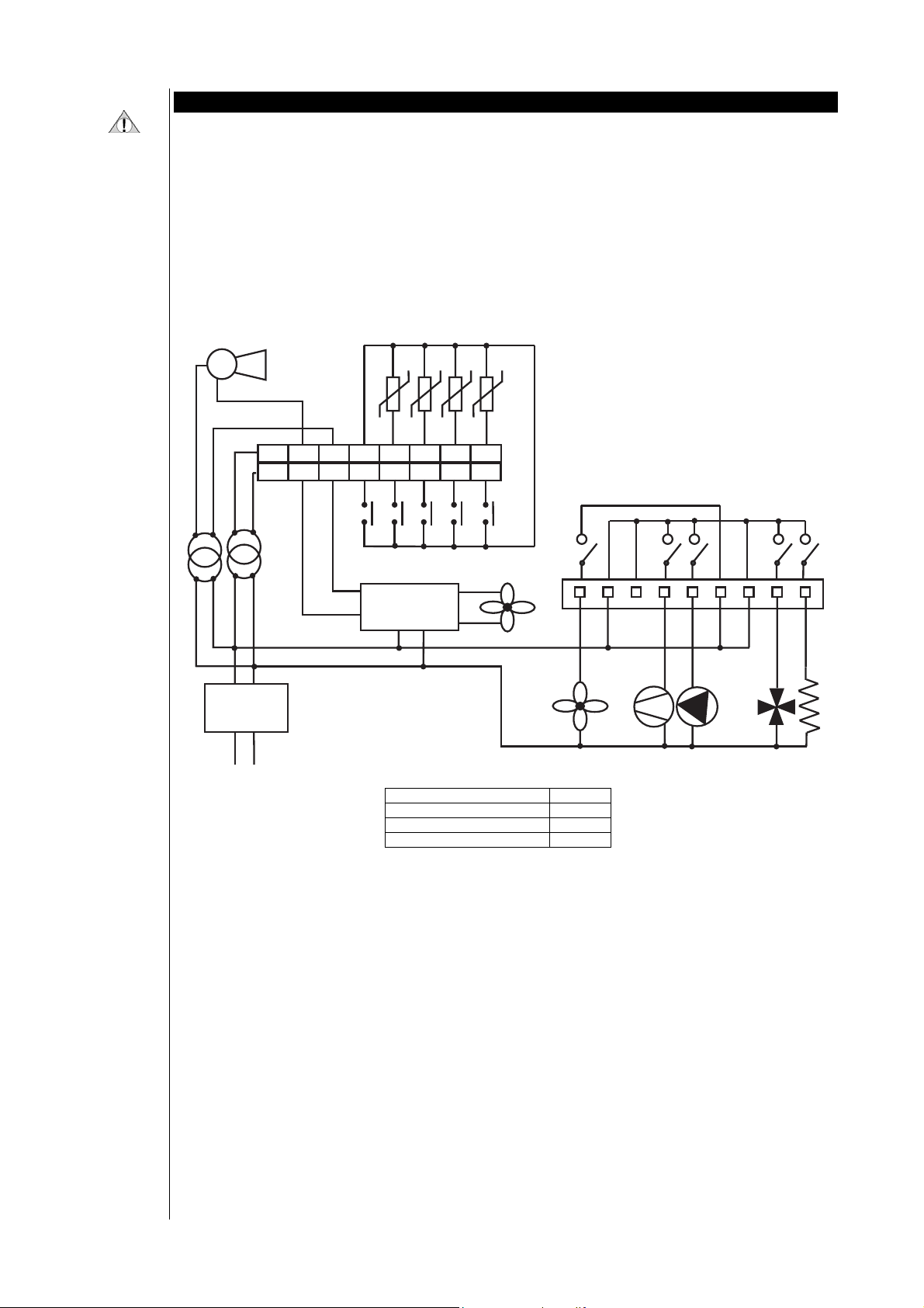
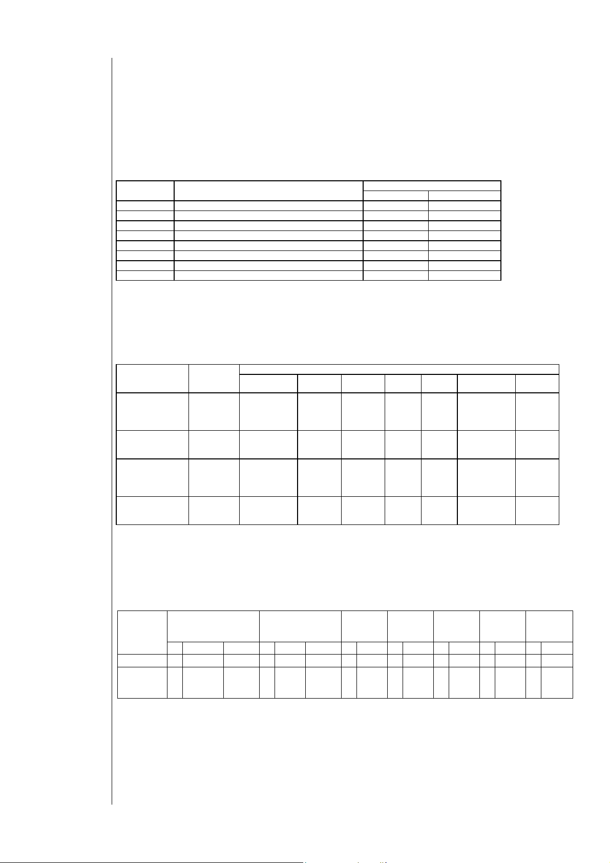
4.1 Connection diagrams
There are 2 ECH 200 BD models:
• ECH 210 BD: 2 step chiller + modbus
• ECH 215 BD: 2 step chiller + modbus
A
12AC AI1
12AC
GNDALL GND AI4 AI3 AI2
12DC TC ID5 ID4 ID3
ID2
ID1
D E F G H
C
B
Line
A: alarm output E: relay 1
B: LC filter F: relay 2
C: CF control G: relay 3
D: TK/relay 5 (only for 215B) H: relay 4
ECH 200 BD
8/76
Page 9
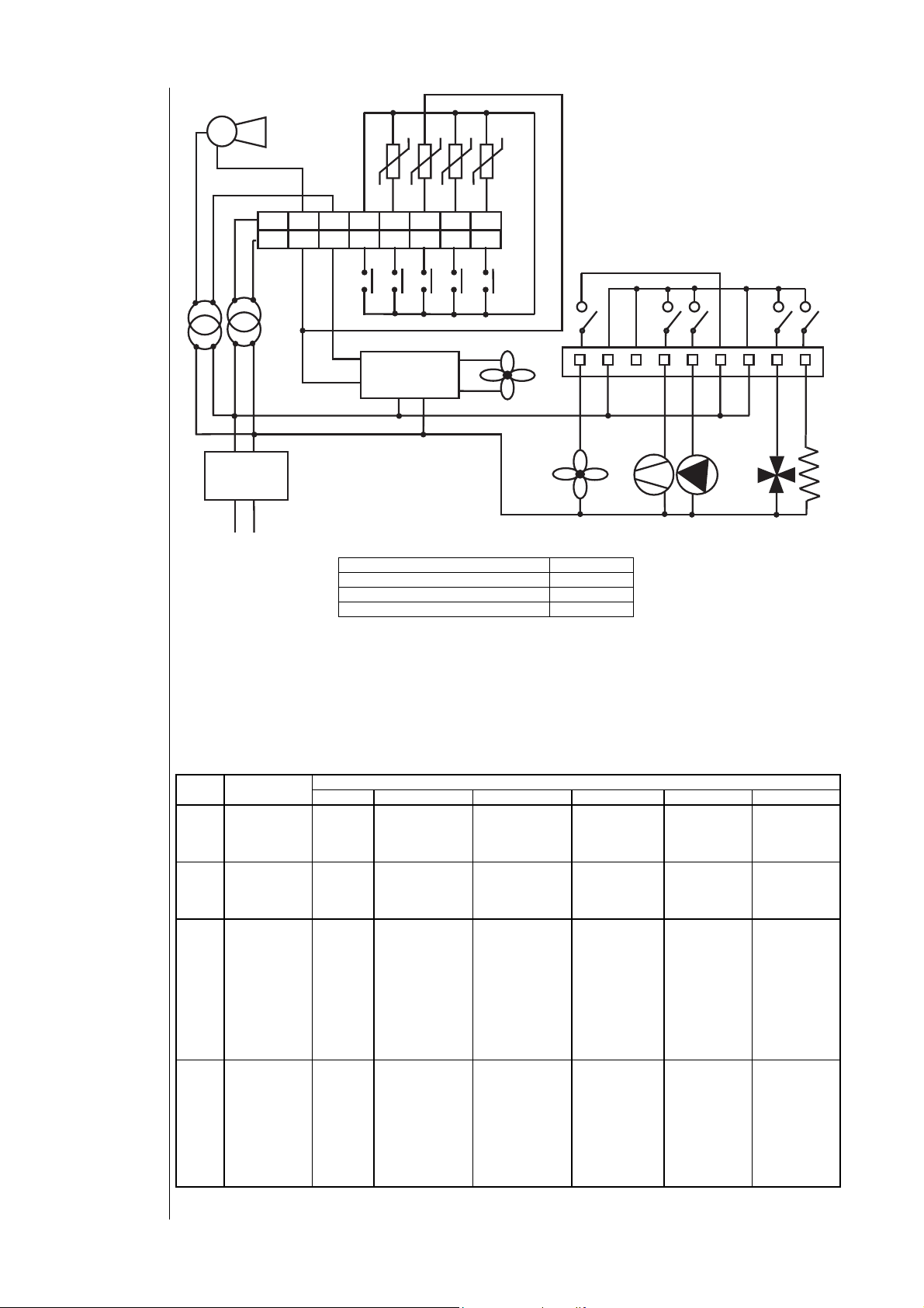
Connection to
probe AI3
configured as
4..20mA C
A
12AC AI1
12AC
GNDALL GND AI4 AI3 AI2
12DC TC ID5 ID4 ID3
ID2
ID1
D E F G H
C
B
Line
Instrument configuration is determined by the values of the parameters associated with inputs and outputs.
A: alarm output E: relay 1
B: LC filter F: relay 2
C: CF control G: relay 3
D: TK/relay 5 (only for 215 BD) H: relay 4
Analogue inputs
Analogue inputs:
configuration
table
4.2 Configuration of analogue inputs
There are 4 analogue inputs:
• 3 NTC type temperature probes
• 1 input which may be configured for an NTC probe or a 4...20 mA signal.
The inputs, which shall henceforth be referred to as AI1…AI4, are configured as shown in the table below:
Pa. Description
Pa
H05
Pa
H06
Pa
H07
Pa
H08
Configuration
of analogue
input AI1
Configuration
of analogue
input AI2
Configuration
of analogue
input AI3
Configuration
of analogue
input AI4
0 1 2 3 4 5
Probe
absent
Probe
absent
Probe
absent
Probe
absent
NTC input
Inlet water/air
NTC input
Outlet
water/air, antifreeze
NTC input
Condensation
NTC input
Condensation
Digital input
Request for
heating
Digital input,
Request for
cooling
4...20 mA input
for
condensation
Multifunctional
digital input
Value
Digital input
Request for
regulation
algorithm
Digital input
for antifreeze
alarm
4...20 mA input
for dynamic
set point
NTC input
Outdoor
temperature
NTC input
Differential
Not permitted Not permitted
NTC input
Anti-freeze
for waterwater
machines with
automatic
(internal)
reversing of
coolant gas
NTC input
Anti-freeze
for waterwater
machines with
automatic
(internal)
reversing of
coolant gas
Not permitted
NTC probe
Regulation
alogorithm in
heating mode
for waterwater
machines with
manual
reversal on
water side
Not permitted
ECH 200 BD
9/76
Page 10
Digital inputs
Digital inputs:
polarity
Digital inputs:
configuration
table
If input AI3 is defined as a 4...20 mA input, the scale bottom value of the pressure input is also signfiicant: Pa H09,
maximum input value; sets the corresponding value to a current of 20 mA
4.3 Configuration of digital inputs
There are 5 voltage-free digital inputs, which will henceforth be identified as ID1…ID5.
AI1, AI2 e AI4 may be added to these if they are configured as digital inputs (through parameters Pa H05, Pa H06, and Pa
H08).
A total of 8 digital inputs is thus available.
The polarity of digital inputs is determined by the parameters listed below:
Parameter Description
Pa H10 Polarity of digital input ID1 Active if closed Active if open
Pa H11 Polarity of digital input ID2 Active if closed Active if open
Pa H12 Polarity of digital input ID3 Active if closed Active if open
Pa H13 Polarity of digital input ID4 Active if closed Active if open
Pa H14 Polarity of digital input ID5 Active if closed Active if open
Pa H15 Polarity of input AI1 (configured as digital) Active if closed Active if open
Pa H16 Polarity of input AI2 (configured as digital) Active if closed Active if open
Pa H17 Polarity of input AI4 (configured as digital) Active if closed Active if open
Inputs ID1 and ID2 cannot be configured and fulfill the following functions:
• ID1 : High pressure input
• ID2 : Low pressure input
The functions of the other inputs may be configured using parameters:
• AI1, AI2: (Refer to Analogue inputs: configuration table)
• ID3, ID4, ID5 and AI4: as shown in the table below
Digital input
configuration
parameters
Configuration
parameter ID3
Configuration
parameter ID4
Configuration
parameter ID5
Configuration
parameter AI4
If more than one of the parameters appearing in table 3 is configured with the same value, the function will be called up
in response to at least one of the inputs.
Parameter
code
Pa H18 Thermal
Pa H19 Thermal
Pa H20 Thermal
Pa H21 Thermal
0 1 2 3 4 5 6
switch
compressor 1
switch
compressor 1
switch
compressor 1
switch
compressor 1
Thermal
switch fan
Thermal
switch fan
Thermal
switch fan
Thermal
switch fan
Flow
switch
Flow
switch
Flow
switch
Flow
switch
Value
Remote
heat
cool
Remote
heat
cool
Remote
heat
cool
Remote
heat
cool
Value
0 1
Remote
On-off
Remote
On-off
Remote
On-off
Remote
On-off
Thermal
switch
compressor 2
Thermal
switch
compressor 2
Thermal
switch
compressor 2
Thermal
switch
compressor 2
Request
step 2
Request
step 2
Request
step 2
Request
step 2
4.4 Configuration of outputs
Outputs
The table below shows the outputs depending on the model with the symbols used in the labels that are associated to the
instrument and that will be shown next to the tabel.
Model
N° Symbol Capacity N° Symbol Capacity N° Symbol N° Symbol N° Symbol N° Symbol N° Symbol
ECH 210 BD 4 NO1..NO4 2A 1 TK 2A -- -- 1 KEYB 1 SERIAL 1 ALL 1 TC
ECH 215 BD 5 NO1..NO5 2A 0 -- -- 1
Relays Triac Optional Keyboard Serial Alarm
EXP
(digital) 1 KEYB 1 SERIAL 1 ALL -- --
ECH 200 BD
Fan
modules
piloting
10/76
Page 11

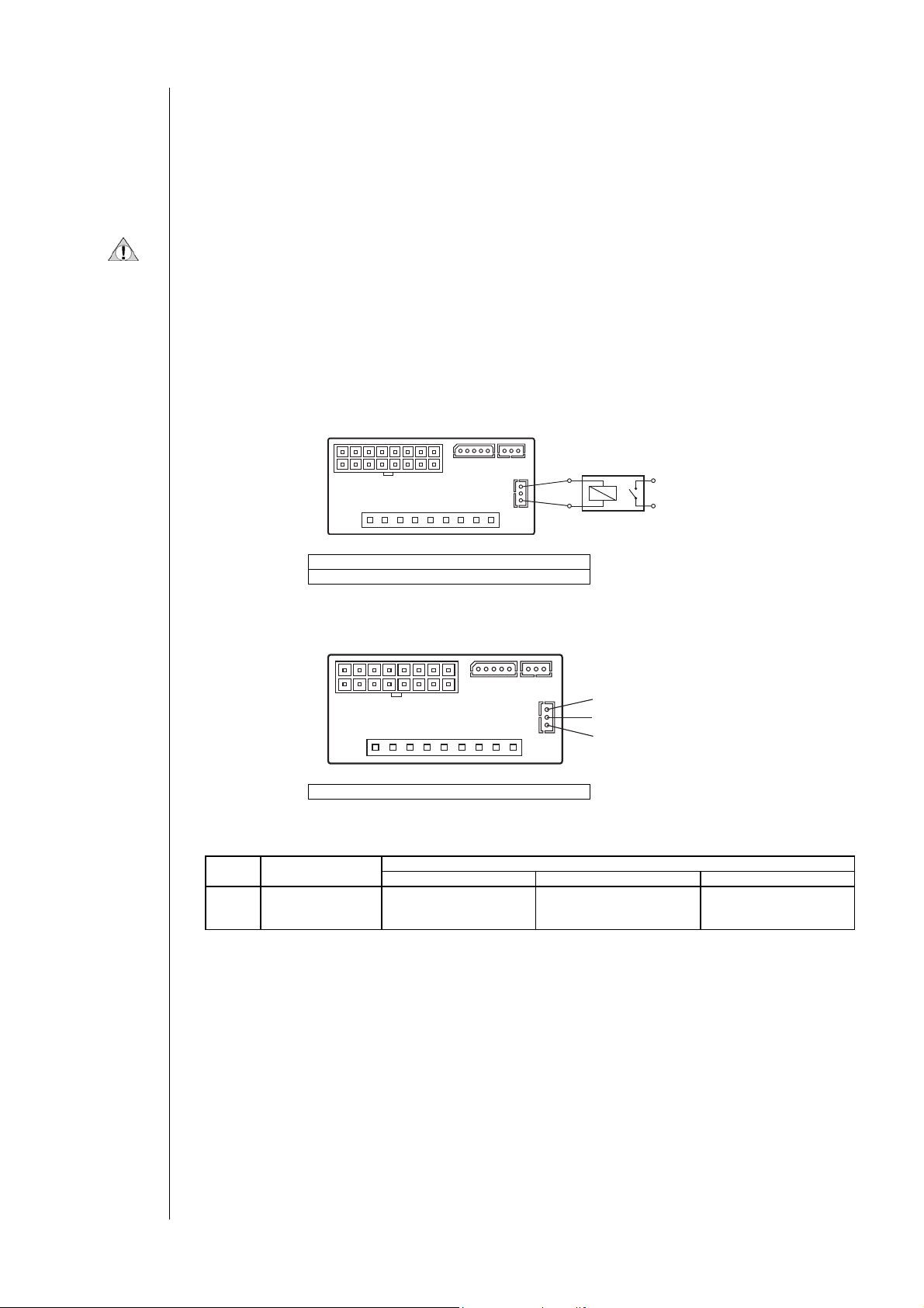
Labels
Relays:
configuration
table
12~ ALL GNDGND
RELAYS 2(2)A 250V~
TRIAC(TK) 2A 250V~
Model Ech 210 BD
12~ ALL GNDGND
RELAYS 2(2)A 250V~
Model Ech 215 BD
4.4.1 Relays
• NO1 - compressor, 2A resistive 250V~ (¼ HP at 240V~ , 1/8 HP 120V~ )
• NO2 - configurable, 2A resistive 250V~ (¼ HP at 240V~ , 1/8 HP 120V~ )
• NO3 - configurable, 2A resistive 250V~ (¼ HP at 240V~ , 1/8 HP 120V~ )
• NO4 - configurable, 2A resistive 250V~ (¼ HP at 240V~ , 1/8 HP 120V~ )
• NO5 – fan on-off, 2A resistive 250V~ (¼ HP at 240V~ , 1/8 HP 120V~ ) (for model ECH 215BD only)
Outputs NO2, NO3, NO4 may be configured as shown in the table below:
Pa. Description
Pa
H22
Pa
H23
Pa
H24
If multiple outputs are configured to run the same resource, the outputs will be activated in parallel.
The maximum load present on the different outputs simultaneously must NOT exceed 8A
IA3 IA2 IA1IA4
ID3 ID2 ID1ID4ID5TC12~ 12=
IA3 IA2 IA1IA4
ID3 ID2 ID1ID4ID5TC12~ 12=
Relay NO2
Pump Internal fan speed 1 Not permitted Not permitted
configuration
Relay NO3
Reversing valve Internal fan speed 3 Second compressor or
configuration
Relay NO4
configuration
Anti-freeze electrical
heaters
SERIAL KEYB
NO1 NO2 NO3 NO4TK NNN
3456789 2 1
SERIAL KEYB
NO1 NO2 NO3 NO4NO5 NNN
3456789 2 1
EXP
Value
0 1 2 3
Not permitted
capacity step
Internal fan speed 2 Boiler Not permitted
TK output:
configuration
table
4.4.2 Triac
• TK – control of condensation fan or supplementary anti-freeze electric heaters.
For model Ech 210 BD the maximum current is 2A-250V~.
For model Ech 210 BD NO downstream remote control of triac is permitted
For model Ech 215B NO triac is expected.
The TK output may be configured as shown below:
Pa. Description
Pa F01 Configuration of
TK output
Proportional
condensation fan
control
0 1 2 3
ON-OFF temperature
fan control
Value
Anti-freeze electric
heaters for waterwater machines
with gas reversal
ON-OFF fan
control in
response to
compressor
Page 12
Open collector
output
4.4.3 Alarm
ALL - 12-24 V~ output for alarm, maximum current 500 mA.
For models Ech 2xx BD the following parameters are available:
Pa H56 = determines the polarity of the alarm output:
• 0 = output is active (closed contact) when an alarm is active and when the machine is switched off.
• 1 = in the same conditions, the contact is open
Pa H57 = determines if the alarm is on with the machine on off from keyboard, with remote off and on stand-by
• 0 = alarm output not enabled in OFF or standby
• 1 = alarm output enabled in OFF or standby
The power supply to the alarm output must be kept separate from the controller power supply.
4.4.4 Fan module pilot output
TC - low voltage output piloting external fan control modules.
4.4.5 Optional output
EXP – optional internal output with configurable output.
For model Ech 210 BD the optional output is digital type and is open collector for piloting the second compressor’s relay:
REAR VIEW
4-20 mA or 0-10 V
output
Optional output:
configuration
table
CONN A
CONN B
SERIAL KEYB
EXP
EXTERNAL RELAY
Rear view: rear view of the control module
External relay: external relay
For model Ech 215 BD the optional output is ANALOGUE type and can be used for piloting 4-20mA or 0-10V fans (through
parameter Pa H25)
REAR VIEW
SERIAL KEYB
CONN A
CONN B
EXP
4-20 mA
GND
0-10 V
Parameter Pa H25 must be configured to suit the version used, as shown
in the table below:
Pa. Description
Pa H25 Optional output
configuration
parameter
The analogue output value is directly proportionate to the external fan control.
For example: if the external fan control has an output of 50%,
• with Pa H25= 1, the 4...20 mA output will have a value of 12 mA (50% calculated on the range 4…20), while the 0-10
V output will not be significant.
• with Pa H25= 2, the 0-10 V output will have a value of 5 V (50% calculated on the range 0…10), while the 4...20 mA
output
will not be significant.
Rear view: rear view of the control module
0 1 2
Open Collector output for
compressor 2
Value
Proportional condensation
fan control, 4-20 mA
Proportional condensation
fan control, 0-10 V
4.4.6 Remote keyboard output
• KEYB - The keyboard output may be used for a remote keyboard.
Connect as shown in the diagram below:
ECH 200 BD
12/76
Page 13
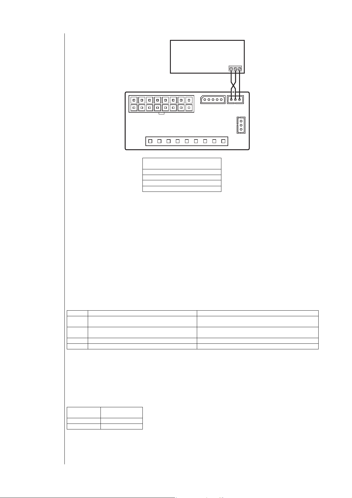
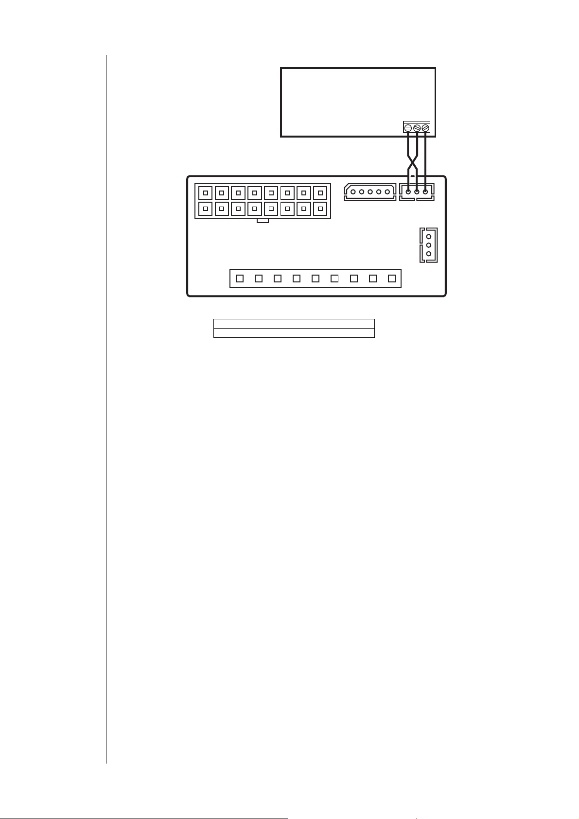
REAR VIEW
CONN A
REMOTE KEYBOARD
24 25 26
SERIAL KEYB
Temperature-
based operation
Pressure-based
operation
Temperature- or
pressure-based
operation:
configuration
table
CONN B
EXP
4.5 Physical quantities and units of measurement
4.5.1 Temperature- or pressure-based operation
Parameter Pa H49 may be used to select two different types of machine: operated on the basis of temperature or of
pressure.
• If Pa H49= 0, parameters Pa H07=0 (probe AI3 absent), Pa F01 = 3 are forced (operation in response to a request
from the compressor) .
• if Pa H49= 1 (temperature-based operation), parameters Pa HO7, F01 are forced as follows: H07= 1 (probe AI3
operating on the basis of temperature), F01= 3 (operation in response to a request from the compressor). During
defrosting, Pa d08 will be used as the defrost start temperature, and Pa d09 as the defrost end temperature.
REMOTE KEYBOARD: Remote
keyboard
REAR VIEW: Rear view
24: blue
25: white
26: black
• if Pa H49= 2 (pressure-based operation), parameters Pa H07, F01 will be forced as follows: H07= 2 (probe AI3
operating on the basis of pressure), F01= 0 (proportional operation). During defrosting the following parameters are
used: Pa d02 as the defrost start pressure and Pa d04 as the defrost end pressure.
• If Pa H49= 3, there are no constraints on the parameters.
Pa H49 Pa H07 Pa F01
0 0 probe AI3 absent 3 operation in response to a request from the
1 1 probe AI3 temperature 3 operation in response to a request from the
2 2 probe AI3 pressure 0 proportional operation
3 No constraints No constraints
compressor
compressor
4.5.2 Units of measurement
Control temperature may be displayed in:
• degrees °C, with decimal point
• degrees °F without decimal point.
Please remember the connection between the two measurement units: °F = °C x 9/5 + 32
The unit of measurement is determined by setting parameter H52:
Pa H52 Unit of
measurement
0 Degrees °C
1 Degrees °F
ECH 200 BD
13/76
Page 14
Connection of
Copy Card
4.6 Serial outputs
There are 2 asynchronous outputs on the control:
• channel for serial communication with a personal computer through an Eliwell interface module
• channel for serial communication with a standard Eliwell keyboard. Power supply 12 VDC (2400, e, 8, 1).
4.6.1 Copy card device
Copy Card is a device that, if connected to the TTL serial port, allows to quickly program the instrument parameters. The
connection diagram is shown below:
C
D
Uploading and downloading data is made as follows:
UPLOAD (copy from INSTRUMENT TO COPY CARD)
This operation allows to download programming parameters to Copy Card.
Operations to be performed are:
• Insert the Copy Card when the instrument is on
• A password will be requested to perform this operation
• On the display, it is shown - - -
• Type the password value corresponding to the parameter value Pa H47
• Hold down both keys
• On uploading , a display appears - - -
• Disconnect Copy Card
Before performing UPLOAD, Copy Card is formatted.
This operation causes all data entered in the Copy Card to be cleared.
The formatting operation cannot be cancelled.
DOWNLOAD (copy from COPY CARD to INSTRUMENT)
This operation allows to upload programming parameters to instrument.
Operations to be performed are:
• Insert the Copy Card when the instrument is off
• Turn on the instrument
• Start uploading parameters into the instrument
• On uploading, Occ appears on the
• If the copy fails, Err appears on the display
• Turn off the instrument
• Disconnect Copy Card
• Turn on the instrument
A: Copy Card device
B: connection through TTL cable
C: channel for serial
communication
D: basic module
B
display
A
ECH 200 BD
14/76
Page 15
Keyboard
mode
On-off – Reset
alarms
Mode and on-off
combinations
: set
5 USER INTERFACE
The interface on the front panel of the instrument can be used to carry out all the operations connected to the use of the
instrument, and in particular to:
• Set operating mode
• Respond to alarm situations
• Check the state of resources
5.1 Keys
Selects operating mode:
• If the heating mode is enabled, each time the key is pressed the following sequence occurs:
stand-by Æ cooling Æ heating Æ stand-by
• if heating mode is not enabled:
stand-by Æ cooling Æ stand-by
In menu mode, this key acts as a SCROLL UP or UP key (increasing value).
Resets alarms, and turns the instrument on and off.
Press once to reset all manually reset alarms not currently active.
Hold down the key for 2 seconds to turn the instrument from on to off or vice versa. When it is off, only the decimal
point remains on the display. In menu mode this key acts as a SCROLL DOWN or DOWN key (decreasing
value)
Pressing the “mode” and “on-off” keys at the same time.
If you press both keys at the same time and then release within 2 seconds, you will move one level deeper in the display
menu.
If you press both keys for more than 2 seconds you will move one level up.
If you are currently viewing the lowest level in the menu and you press both keys and release within 2 seconds, you will go
up one level.
5.2 Displays
The device can provide information of all kinds on its status, configuration, and alarms through a display and leds on the
front panel.
5.2.1 Display
Normal display shows:
• regulation temperature in tenths of degrees celsius with a decimal point, or in degrees fahrenheit without a
decimal point.
• the alarm code, if at least one alarm is active. If multiple alarms are active, the one with greater priority will be
displayed, according to the Table of Alarms.
• If temperature control is not analogue and depends on the status of a digital input (AI1 or AI2 configured as
digital inputs), the “On” or “Off” label will be displayed, depending on whether temperature control is active or
not.
• When in menu mode, the display depends on the current position. Labels and codes are used to help the user
identify the current function.
• Decimal point: when displaying hours of operation, indicates that the value must be multiplied x 100
5.2.2 SET display for air-air machines (for models Ech 2xxB only)
To make easier the user interface in air-air versions, if iyou place parameter Pa H53 = 1, the set for the selected mode will
be displayed; pressing UP e DOWN keys on the remote keyboard directly modifies the set of the current mode. You cannot
directly modify the set in the local keyboard.
ECH 200 BD
15/76
Page 16
5.2.3 Led
Led compressor 1.
• ON if compressor 1 is active
• OFF if compressor 1 is off
• BLINK if safety timing is in progress
Compressor 2 (or capacity step) led
• ON if compressor (capacity step) is on
• OFF if compressor (capacity step) is off
• BLINK if safety timing is in progress
Defrost led
• ON if defrosting is in progress
• OFF if defrosting is disabled or has been completed
• BLINK if timing is in progress (defrost interval)
Electrical heater/boiler led
• ON if the internal anti-freeze electrical heater or boiler is on
• OFF if the internal anti-freeze electrical heater or boiler is off
Heating led
• ON if the device is in heating mode
Cooling led
• ON if the controller is in cooling mode
If neither the HEATING led nor the COOLING led is on, the controller is in STAND-BY mode
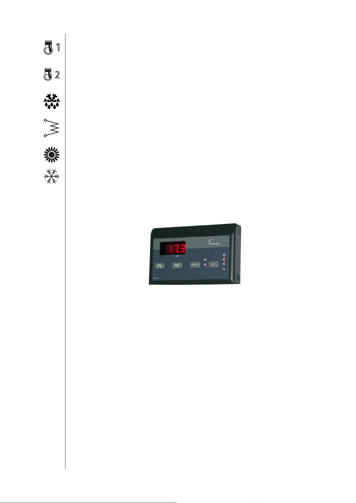
5.3 Remote keyboard
The remote keyboard on the display is an exact copy of the information displayed on the instrument, with the same leds;
Remote keyboard
It performs exactly the same functions as those described in the display section.
The only difference is in use of the UP and DOWN keys (to increase and decrease value), which are separate from the
MODE and ON/OFF keys.
Connection with the controller is illustrated below:
ECH 200 BD
16/76
Page 17
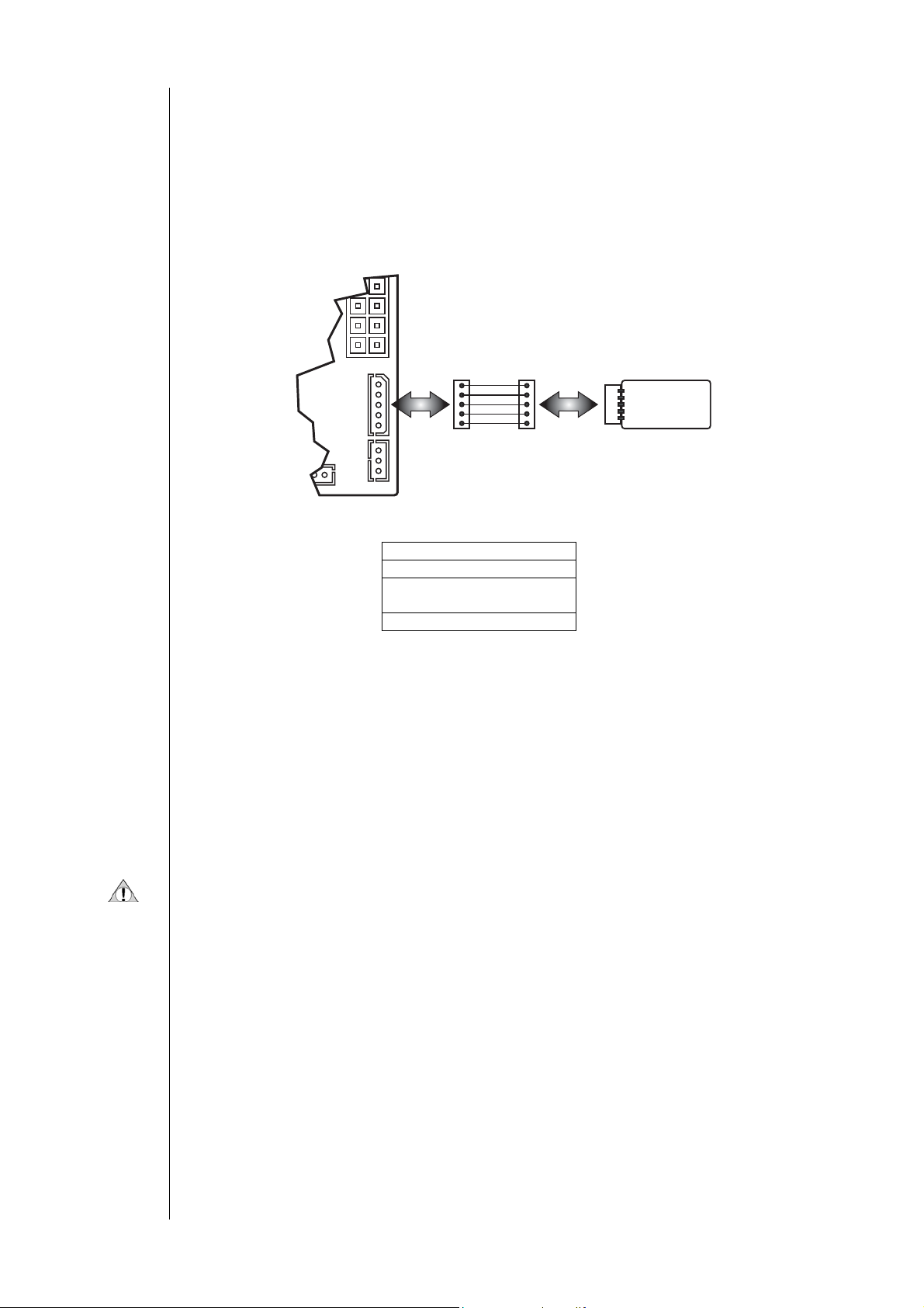
REAR VIEW
CONN A
REMOTE KEYBOARD
24 25 26
SERIAL KEYB
CONN B
EXP
REMOTE KEYBOARD: Remote keyboard
REAR VIEW: rear view of the control module
ECH 200 BD
17/76
Page 18

The terminals of the remote keyboard are associated with the following colours:
• 24 Æ blue
• 25 Æ red
• 26 Æ black
Be cautious when connecting these terminals because they are reversed against the connector’s terminals.
5.4 Parameter programming – Menu levels
Device parameters may be modified using a Personal Computer (with the required software, interface module and cables),
or using the keyboard.
If using the keyboard, access to parameters is arranged in a hierarchy of levels which may be accessed by pressing the
“mode and “on-off” keys at the same time (as described above).
Each menu level is identified by a mnemonic code which appears on the display.
ECH 200 BD
18/76
Page 19
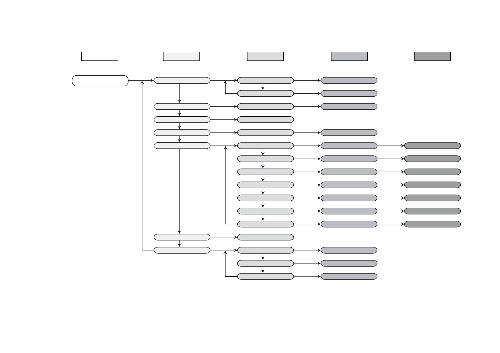
Menu structure
The structure is set up as shown in the diagram below:
Level 0 Level 1 Level 2 Level 3
Level 4
Control Probe
Current Alarm
Set point SEt
Analogue Inputs TP
Alarms Err
Digital inputs Id
Parameters PAr
Password Pss
Operating Hours
OHr
Label Set Cooling Coo
Label Set Heating HEA
Input Code t01...t04
Current alarms Code E00
Input Code 01...05
Configuration Parameters CnF
Compressor Parameters CP
Fan Parameters FAn
Alarm Parameters ALL
Pump Parameters PUP
Antifreeze Parameters Fro
Defrost Parameters dFr
Password Value
Compressor 1 hours OH1
Set Cooling Value
Set Heating Value
Analogue Input Value
Digital Input Status
Parameter Index H01...
Parameter Index C01...
Parameter Index F01...
Parameter Index A01...
Parameter Index P01...
Parameter Index r01...
Parameter Index d01...
Number of hours Parameter
Parameter Value
Parameter Value
Parameter Value
Parameter Value
Parameter Value
Parameter Value
Parameter Value
Compressor 2 hours OH2
Pump hours OPH
ECH 200 BD
Number of hours Parameter
Numero ore parameto
19/76
Page 20

Label
5.4.1 Visibility of parameters and sub-menus
With a personal computer, interface key (copy card), suitable cables and the “Param Manager” software, it is possible to
restrict the visibility and modification of parameters and entire submenus.
A “visibility value” may be assigned to each parameter, as described below:
Value Meaning
0003 Parameter or label visible at all times
0258 Parameter or label visible if user password entered correctly (password = Pa
H46)
0770 Parameter or label visible if user password entered correctly (password = Pa
H46). Parameter cannot be modified.
0768 Parameter visible from PC only.
Some visibility settings are factory set.
For more information, please refer to the “Param Manager” instructions.
Page 21
Power step
f
Polarity NO3
6 SYSTEM CONFIGURATION
In this section we will look at how to configure parameters for various loads on the basis of the type of installation to be
controlled.
6.1 Compressors
Ech 200 BD can control systems consisting of one cooling circuit with 1 or 2 compressors.
If there is a capacity step, it will be considered as a compressor.
Each compressor is piloted by a device relay.
Compressors will turned on or off depending on the temperatures detected and the temperature control functions that
have been set (refer to the section on Compressor controls – regulation algorithm)
6.1.1 Compressor configuration
The first compressor must be connected to output NO1;
The second compressor, if there is one, must be connected to output NO3, with the following parameter settings:
• Pa H48=2 (2 compressors per circuit)
• Pa H23=2 (output NO3 configured as compressor/capacity step) or Pa H25=0 (open collector output for the
second compressor/capacity step).
If the open collector output is used, an external relay will be required for compressor management.
If NO3 is configured as a second compressor/capacity step output, polarity may be selected using the parameter
Pa H51, polarity of compressor 2/ capacity step output (on relay 3 only).
• 0= relay ON if compressor 2/ capacity step ON,
• 1= relay ON if compressor 2/ capacity step OFF.
The polarity of NO1 is unvariable:
• relay ON if compressor 1/ capacity step ON
Balancing hours of
operation
Unvaried sequence
Safety timing
Of
-on timing
On-on timing
Off-on and on-on
comp. diagram
6.1.2 Compressor on/off sequence
The order in which the compressors come on may be modified using parameter Pa H50, compressor on sequence:
• Pa H50=0 compressors come on depending on the number of hours of operation (balancing hours of operation)
• Pa H50=1 compressor 1 is turned on first, followed by compressor (or capacity step) 2 (unvaried sequence).
If Pa H50= 0, the compressor with the least hours of operation comes on first, unless it is subject to:
a current compressor shutdown alarm (refer to table of alarms)
safety timing in progress.
If Pa H50= 0, the compressor with the most hours of operation is turned off first.
If Pa H50=1:
compressor 2 (capacity step) is turned on only if compressor 1 is already on.
compressor 1 is turned off only if compressor 2 (capacity step) is already off. If there is a compressor 1 shutdown alarm,
compressor 2 will be turned off immediately.
6.1.3 Compressor timing
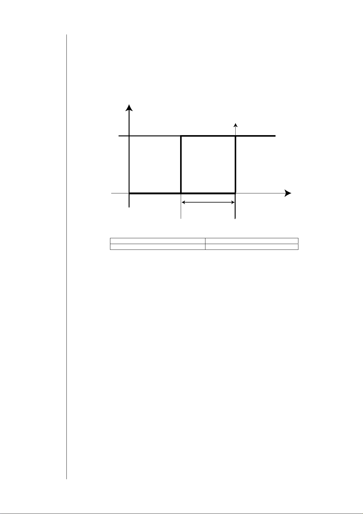
The turning on and off of compressors must comply with safety times which may be set by the user using the parameters
specified below:
There is a safety interval between the time a compressor goes off and the time the same compressor comes back on
(compressor on…off safety time, controlled by parameter Pa C01);
This interval of time must elapse when the “ECH 200 BD” is turned on.
There is a safety interval between the time a compressor is turned on and the time it is turned on again (compressor
on...on safety time, controlled by parameter Pa C02) .
COMPR
ON
OFF
Pa C01
Pa C02
Time
COMPR: compressor Time: seconds x 10
Pa C01: ON-OFF safety time Pa C02: ON-ON safety time
Page 22
On-on and off-off
Timing
diagram for 2
comp.
On-on and off-off
diagram for 2
comp.
If the system includes 2 compressors (or capacity steps) there are intervals of time which must pass between turning on of
the 2 compressors (Pa C06) and turning off of the 2 compressors (Pa C07). An amount of time determined by parameter
Pa D11 (compressor on delay during defrosting) must pass between turning on a compressor and a capacity step.
The off time interval between compressors is not applied in the event of a compressor shutdown alarm, in which case
they stop immediately.
COMPR1
ON
OFF
COMPR2
ON
OFF
Pa C05
Pa C07
Time
Time
COMPR1: compressor 1
COMPR2: compressor 2
Time: time in seconds
Pa C05: on time interval between
compressors
Pa C07: off time interval between
compressors
6.2 Condensation fan
Various fan piloting modules can be connected to “Ech 200”, based on the models available
Look at the following table:
Ech 210 * *
Legend:
6.2.1 Fan configuration
The reference is to the fan control unit located outside near the heat exchanger which normally acts as a condenser. If a
heat pump is used, the exchanger will operate as an evaporator.
First of all, connect the fan up correctly to the appropriate output (refer to connection diagrams).
The fan output may be configured to work proportionately or as ON-OFF.
Pa F01 – Selection of triac output mode (TK and TC):
The fan may also be controlled by the output associated with the optional board:
Pa H25 – configuration of optional board:
If the output is configured as proportional TK the PICK-UP, PHASE SHIFT and IMPULSE DURATION parameters are also
significant.
TK TC 4-20mA 0-10V
• TK: 230V~/2A command
• TC: control signal for fan control modules (500w,1500w,2200w)
• 4-20mA o 0-10V: standard command for fan control through external module (inverter).
• On model Ech 210 BD, the fan may be controlled with a proportionate output with a maximum load of 2A.
• 0= proportional fan output (TK)
• 1= ON-OFF fan output; in this mode the fan will be off if the proportional control has an output of 0 , on at
maximum speed (no capacity step) if control output is greater than 0.
• 2= external anti-freeze electrical heater control, for water-water machines with gas reversal
• 3= fan command for ON-OFF operation in response to compressor request. In this mode the fan is turned off
and on depending on compressor status.
• 0= Open Collector output for second compressor
• 1= 4...20 mA fan speed output
• 2= 0-10 V fan speed output
ECH 200 BD
22/76
Page 23
Pick-up
Phase shift
Impulse duration
Connection
diagram of the
DRV module
Every time the external fan is started up, power is supplied to the exchanger fan at maximum voltage, and the fan operates
at maximum speed, for an amount of time equal to Pa F02 seconds; after this time the fan operates at the speed set by
the regulator.
Pa F02 = Fan pick-up time (seconds)
Determines a delay during which it is possible to compensate the different electrical characteristics of the fan drive
motors:
Pa F03 = duration of fan phase shift, expressed in microseconds x 200.
Determines the duration of the TK output piloting impulse in microseconds x 200
Pa F04= triac piloting impulse duration
6.2.2 DRV module
If a DRV three-phase fan module is used, follow the diagram below:
DRV
J5=3
J6=on
J7=on1
Energy/EWCM
12
12
12
TC
1
J8=off
2
3
4
Polarity
Continuous
operation
TF
TF: current
transformer
6.3 Reversing valve
The reversing valve is used only when operating in “heat pump” mode.
It is active if:
• relay 3 configuration parameter Pa H23= 0.
• heat pump is enabled, Pa H28= 1.
The reversing valve is off if the instrument is OFF or on stand-by.
Polarity may be configured using the following parameter:
Pa H38= Reversing valve polarity
• 0: relay active in cool mode
• 1: relay active in heat mode
In cooling mode the reversing valve is never active.
6.4 Hydraulic pump
The hydraulic pump must be connected to the output of relay NO2 (refer to connection diagram).
It is active only if the corresponding parameter, Pa H22, is set to 0.
The pump may be configured to function in three different ways using parameter Pa P01:
• Pa P01 = 0 : continuous operation
• Pa P01 = 1 : operation when called up by regulation algorithm (compressor)
• Pa P01 = 2 : cyclic operation
CONTINUOUS OPERATION:
Pump is on at all times.
ECH 200 BD
23/76
Page 24

Operation in
response to
request
OPERATION IN RESPONSE TO REQUEST:
• The pump comes on in response to a request from the regulation algorithm.
• The compressor comes on following a delay (Pa P02) after the time the pump comes on.
• The pump goes off following a delay (Pa P03) after the regulation algorithm has OFF status.
• During defrosting, when the compressor is OFF, the pump stays on.
TERM
ON
OFF
Time
COMPR
ON
OFF
Time
WP
ON
Cyclic operation
configuration
OFF
Time
Pa P03Pa P02
CYCLIC OPERATION:
The pump is turned on and off independently of the regulation algorithm. It operates for constant intervals of time, as
described below:
The pump is turned off if:
When there is a current flow switch alarm with automatic resetting (refer to table of alarms), the pump will remain on
even if the compressor is OFF due to the alarm..
6.5 Internal anti-freeze/supplementary electrical heaters
Anti-freeze/supplementary heaters are connected up to relay output NO4 (refer to connection diagram).
They are active only if the corresponding parameter, Pa H24, is set to 0.
If the output is configured this way, it will command the electrical heaters to come on and go off in accordance with the
electrical heater configuration parameters, r01…r06, as described in the table below:
TERM: regulation algorithm COMPR: compressor
WP: pump Time: time in seconds
Pa P02: delay compressor-pump off Pa P03: delay pump-compressor on
• the pump stays on for an amount of time equal to Pa P02 (seconds*10),
• the pump is then turned off and stays off for an amount of time equal to Pa P03 (seconds*10).
• there is an alarm comporting pump shutdown, such as a manually reset flow switch alarm
• the instrument is on stand-by or OFF
Pa. Description
Pa r01 Defrost configuration comes on only when requested
Pa r02 Cooling mode configuration off during cooling On during cooling (depending
Value
0 1
Always on during defrost
by control
on anti-freeze electrical heater
control)
ECH 200 BD
24/76
Page 25

Pa r03 Heating mode configuration off during heating On during heating (depending
Pa r04 Configuration of electrical heater control
probe in heating mode
Pa r05 Configuration of control probe in cooling
mode
Pa r06 Configuration when OFF or on stand-by Off when instrument is OFF or
6.5.1 Supplementary electrical heaters
If Pa r15 =1 electrical heaters become anti-freeze/supplementary electrical heaters.
Their operating mode is described in the paragraph on the supplementary electrical heater control
controlled on the basis of AI1
(refer to connection diagrams)
if Pa H05 (config. AI1)= 1
otherwise off
controlled on the basis of AI1
(refer to connection diagrams)
if Pa H05 (config. AI1)= 1
otherwise off
on stand-by
on anti-freeze electrical heater
control)
Controlled on the basis of AI2
(refer to connection diagrams)
if Pa H06 (config. AI2)= 1
otherwise off
Controlled on the basis of AI2
(refer to connection diagrams)
if Pa H06 (config. AI2)= 1
Otherwise off
On when instrument is OFF or
on stand-by
6.6 External anti-freeze electrical heaters
External anti-freeze electrical heaters are used on water-water machines with gas reversal.
They are connected to the triac TK output (refer to connection diagram) and controlled on the basis of probe AI3 (refer
to analogue inputs) .
They are active only if:
• output TK is configured for anti-freeze electrical heaters, on a water-water machine with gas reversal (Pa F01=
2)
• AI3 is configured as an NTC anti-freeze input on a water-water machine with gas reversal (Pa H07= 4)
6.7 Boiler
The output for boiler controller is relay NO4 (refer to connection diagram) with a suitable configuration.
The boiler output may operate in two different ways:
• to supplement another heating resource
• to provide heating with boiler only.
SUPPLEMENTARY BOILER:
The output is active if:
• relay 4 configuration parameter, Pa H24= 2.
• heat pump is declared present, Pa H28= 1.
• AI4 is configured as an outdoor probe, Pa H08= 3.
HEATING BOILER:
The output is active if:
relay 4 configuration parameter, Pa H24= 2.
heat pump is declared not present (H28= 0)
The boiler is turned off if:
• the device is operating in cooling mode
• the device is on stand-by or OFF
• there is a boiler shutdown alarm (refer to table of alarms)
ECH 200 BD
25/76
Page 26

Minimum time
Actual time
7 ADAPTIVE
ECH 200BD is a special model of the ECH 200 line that features extremely versatile characteristics and features, particularly
suited for small plants.
These are:
• Adaptive function
• Fan control in Defrosting mode
Antifreeze function with heat pump, depending on water pump and heat pump.
7.1 Adaptive function
Chillers are generally equipped with water accumulation tanks.
These provide the thermal inertia required to prevent the compressors from being frequently started or switched off when
the request of heat for the rooms to be cooled is low (frequent start and switching off operations influence the lifecycle of
compressors).
In some cases, the setting of safety limits for the start and switching off operations can delay the start of the compressors
as compared to the requests of the regulation algorithm, thus reducing the efficiency of the whole system.
Example: if a chiller is designed to supply 10 fan coils and only one of these chillers is running in Cooling mode, the
interval of time during which the compressor is expected to stay on is low; in addition the need of complying with the
safety limits would cause an increase of the water temperature above the set point determined by hysteresis.
Accumulation tanks would increase the thermal capacity and provide the inertia required to increase the running time,
though resulting in higher costs and in the need for increasing even the minimum size of the unit.
The Adaptive function, which changes the set points and hysteresis, electronically simulates the inertia of a water
accumulation container, thus also limiting its use.
7.1.1 Adaptive function: regulator
It is useful to remember that the start and switching off operations of compressors must comply with the standards of
safety limits.
The function analyses the actual running time of the compressor (ET) comparing it with the minimum running time that
has been set (MT).
Parameters
• C01 Compressor OFF-ON time
• C02 Compressor ON-ON time
• C08 Enables the Adaptive function
• C09 Set block in Cooling mode
• C10 Set block in Heating mode
• C11 Offset constant
• C12 Reset time for increases
• C13 Proportional Part Offset Coefficient
The minimum time (MT) is represented by the difference between the ON/ON (C02) and the OFF/ON parameter (C01):
• MT = C02 – C01
The actual running time (ET) is automatically registered by the unit.
Adaptive offsets
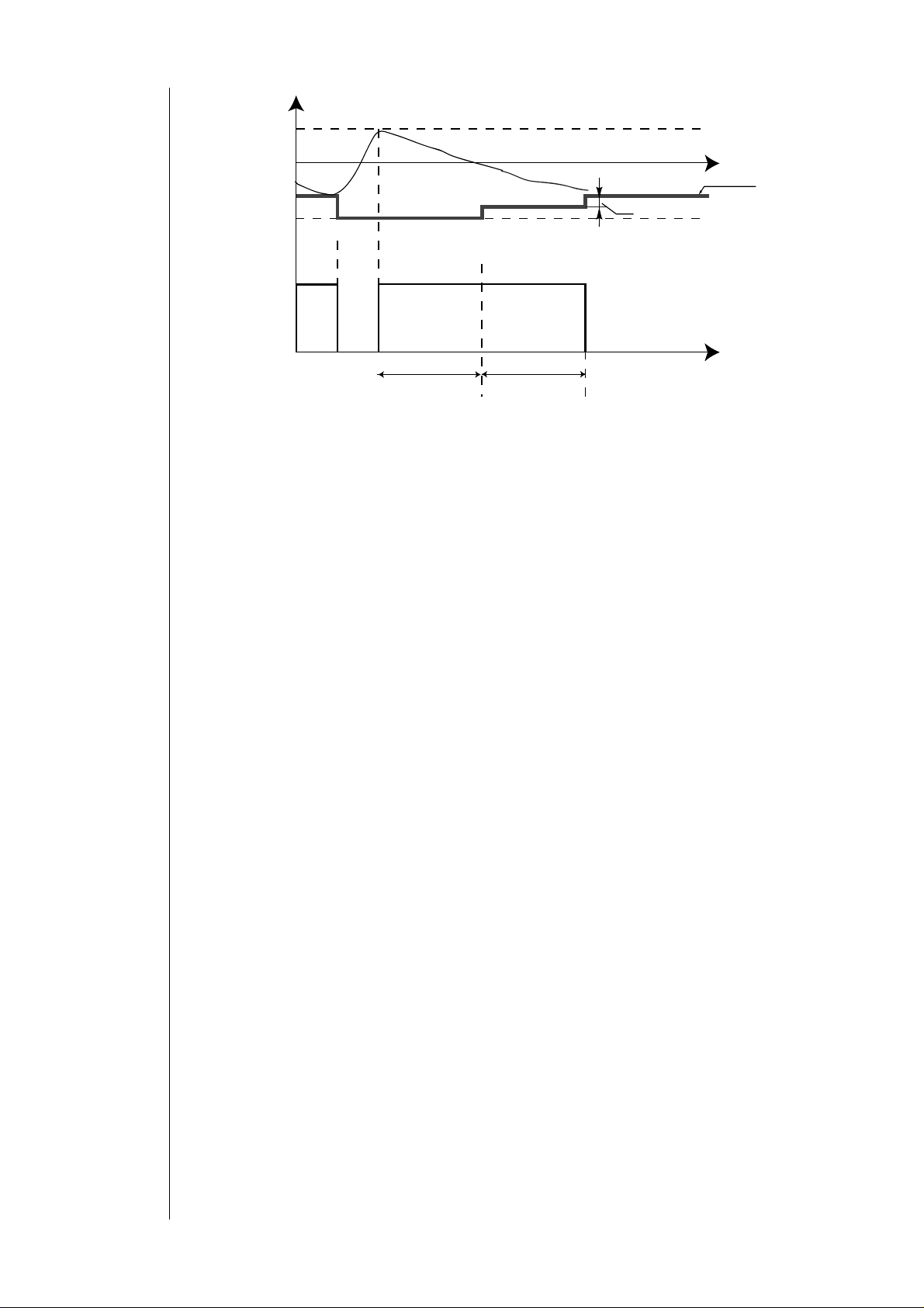
7.1.2 Set point offset (for ET<MT)
The ON set point is changed by a value equivalent to the adaptive offset (AO) according to the formula shown below,
when the compressor is switched off:
• AO=((MT – ET)* C13) + C11
That is
• AO=((C02– C01 – ET)* C13) + C11
• The set point is reduced in “Cooling” mode: SET(1) = SET(COO) – AO(1);
SET(2) = SET(1) – AO(2)
and so on
• The set point is increased in “
Heating” mode: SET(1) = SET(HEA) + AO(1);
SET(2) = SET(1) + AO(2)
and so on
The index associated to the set point and offset values refers to the compressor cycle, after which all variables are
updated. The updated values are then used for the next cycle.
“SET(COO)” and “SET(HEA)” are the original set point values (for example those entered from the keyboard with menus
SET/COO and /HEA).
Page 27
Examples:
set+Int
SET
AO
ON
Comp.
AI1
SET 1
SET 2
Cooling Mode
Heating Mode
OFF
Cycle 0:
• Set point: SET(COO)
• Hysteresis: SET(COO) + C03
Cycle 1:
• Set point for cycle 1: SET(1) = SET (COO) – AO(1)
• Hysteresis for cycle 1: SET(1) + C03 + AO(1) = SET(COO) - AO(1)
Cycle 2:
• Set point for cycle 2: SET(2) = SET (COO) – AO(1) – AO(2)
• Hysteresis for cycle 2: SET(COO) + C03
Cycle 0:
• Set point: SET(HEA)
• Hysteresis: SET(HEA) - C04
Cycle 1:
• Set point for cycle 1: SET(1) = SET (HEA) + AO(1)
• Hysteresis for cycle 1: SET(HEA) - C04 + AO(1) = SET(HEA) - AO(1)
Cycle 2:
• Set point for cycle 2: SET(2) = SET (HEA) + AO(1) + AO(2)
• Hysteresis for cycle 2: SET(HEA) - C04
It is useful to notice that the start temperature in both modes remains constant for each cycle even when the adaptive
function is enabled.
This increases the range between the set point and start temperatures, reducing the number of starts/stops of the
compressor.
ET
MT
ET
MT
+ C03 + AO(1) = SET(COO) + C03
+ C04 + AO(1) = SET(HEA) + C04
7.1.3 Set point regression (for ET≥MT)
If the cycle time is long enough (and not above MT), the regression of the actual set point occurs: the set point is changed
by C11 for each C12 range (starting from the beginning of the cycle).
• In Cooling mode, the set point (applicable to cycle N) is increased:
• In Heating mode, the set point is reduced, as explained above, down to the limit value of SET(HEA).
This produces a balancing of the “adaptive” function with long cycle times because longer cycle times are compatible with
those of the compressor.
Example: cooling
After C12: SET(N) + C11
After 2*C12: SET(N) + 2*C11
And so on, up to limit value of SET(COO)
ECH 200 BD
27/76
Page 28
O
O
Set+Ist
A
C
o
SET
set effettiv
O
C11
AI1
N
omp.
FF
C12
7.1.4 Protection in Cooling mode
If the output temperature is AI2 < C09 during a generic cycle n, the controller performs the following operations:
• Switches the compressor(s) off.
This adjustment can be considered a pre-threshold of the anti-freeze alarm (the cycle ends without generating alarms) if
the adaptive function yields a very low actual set point.
It is advisable to use C09 > A11.
7.1.5 Protection in Heating mode
If the output temperature is AI2 > C10 during a generic cycle n, the controller performs the following operations:
• Switches the compressor(s) off.
This adjustment can be considered a pre-threshold of the anti-freeze alarm (the cycle ends without generating alarms) if
the adaptive function yields a very low actual set point.
The setting of C10 should be chosen according to the high pressure protections in use (pressure switch calibration, type of
coolant used...).
C12
7.1.6 Notes
• The adaptive algorithm is reset (i.e. the original set point is restored) in the conditions listed above and when the
controller is switched off (i.e. not after a manual or remote off or standby condition).
• If the compressor switches off due a thermal switch or equivalent alarm and ET<MT, the actual offset and set
point are updated as if the cycle had been completed (the cycle that follows this alarm will adopt a different set
point).
• If the compressor switches off due to the transition between modes, for example from standby to remote off
(from digital input), and ET<MT, the offset is updated as if the cycle had been completed . The cycle that
7.1.7 Example
The running of the compressor for two minutes will yield the following values:
follows this alarm will adopt the set point selected for the mode +/- offset, depending on the mode).
• Set heat = 45.0 °C
• Set cool = 12.0 °C
• C01 = 18 S*10 (3 minutes)
• C02 = 36 S*10 (6 minutes)
• C08 =1
• C09 = 4 °C
• C10 = 50 °C
• C11 = 0.5 °C
• C12 = 30 S*10 (5 minutes)
• C13 = 0.2 °C/(10*s)
• Minimum time:
MT = C02 –C01 = 36-18 = 18*10*s (3 minutes)
• Actual time:
ET = 12 (12*10*s = 2 minutes)
• Adaptive offset
AO = (MT – ET) * C13 + C11 = (18-12)*0.2 + 0.5 = 1.7°C
• If Heating Mode:
SET(1) = SET(HEA) + AO(1) = 45 + 1.7 = 46.7°C
• If Cooling Mode:
ECH 200 BD
28/76
Page 29
SET(1) = SET(COO) – AO(1) = 12 –1.7 = 10.3
7.2 Fan control in Defrosting mode
During the defrosting phase, the condensing pressure may sometimes reach alarm levels before the heat exchanger has
defrosted all the ice.
To prevent this condition from tripping the high pressure alarm, the unit starts fans at minimum speed if the
pressure/temperature read by probe AI3 is above value F22.
The hysteresis of the regulator is above parameter F11.
FAN
F22
MIN
OFF
F11
The function can be enabled with parameter F21.
FAN : fan AI3: probe AI3
MIN: minimum speed of the fan
AI3
7.3 Antifreeze function for units with heat pump
This function enables the water pump to be used in Antifreeze mode.
If the water temperature is low and the unit is not running in Heating mode, the hydraulic pump starts followed by the
compressor.
The function is always active if A23=1.
If the water pump is off and temperature is AI1< A20, the unit starts the water pump.
If the temperature is AI1<A21, the unit starts the heat pump (if it is off).
This operating is carried out in modes: Off, Standby and Heating with active remote Off.
When the unit displays the Heating mode, it is no longer possible to change the operating mode from the keyboard or by
means of a digital input.
The control resumes normal operation if AI1> A22.
ECH 200 BD
29/76
Page 30

Operating modes
f
Cooling
Heating
Stand-by
Device of
Operating modes:
configuration
table
8 TEMPERATURE CONTROL FUNCTIONS
Once Ech 200 has been configured, loads may be controlled on the basis of temperature and pressure conditions detected
by probes and temperature control functions which may be defined using the appropriate parameters.
There are 4 possible operating modes:
• cooling
• heating
• stand-by
• off
Cooling: this is the “summer” operating mode; the machine is configured for cooling.
Heating: this is the “winter” operating mode; the machine is configured for heating
Stand-by: the machine does not govern any temperature control function; it continues to signal alarms
Off: the machine is turned off.
The operating mode is determined by settings entered on the keyboard and by the following
Parameters:
• Operating mode parameter (Pa H27)
• Heat pump parameter (Pa H28)
• Configuration parameter AI1 (Pa H05) ( refer to Analogue inputs: configuration table)
• Configuration parameter AI2 (Pa H06) (refer to Analogue inputs: configuration table)
Operating mode selection parameter (Pa H27)
• 0= Selection from keyboard
• 1= Selection from digital input (refer to digital inputs)
• 2= Selection from analogue input (probe AI4)
Heat pump parameter (Pa H10)
• 0 = Heat pump not present
• 1= Heat pump present
Heating mode is permitted only if:
• heat pump is present (Pa H28= 1) or
• relay NO4 is configured as boiler output (Pa H24= 2).
Combinations of these parameters will generate the following rules:
Operating mode Mode selection
Mode selection from keyboard 0 Other than 2 Other than 2
Mode selection from digital input. 1 Other than 2 Other than 2
If input AI1 is on, operating mode is heating; if
not, stand-by
If input AI2 is on, operating mode is cooling; if
not, stand-by
If input AI1 is on, operating mode is heating; if
AI2 is on, operating mode is cooling; if AI1 and
AI2 are both on, there is a configuration error; if
neither is on, operating mode is stand-by
parameter
Pa H27
Any 2 Other than 2
Any Other than 2 2
Any 2 2
Configuration
parameter AI1
Pa H05
Configuration
parameter AI2
Pa H06
8.1 Selection of operating mode from analogue input
The controller permits selection of operating mode on the basis of the temperature detected and supplied by input AI4
(refer to analogue inputs).
This is permitted if both of the following conditions apply:
• probe AI4 is configured as an outdoor temperature probe (Pa H08= 3)
• mode selection parameter Pa H27= 2
• In this case mode is selected automatically, on the basis of the following regulation algorithm parameters:
• Heating mode set point Pa H29
• Mode selection differential Pa H30.
Diagram
An example of operation is shown in the diagram below:
Page 31

Mode
Pa H29
Cooling
Heating
Control
parameters
Pa H30
Pa H29: Heating mode set point
Pa H30: Mode selection differential
Ext temp: outdoor temperature
Mode may be changed from the keyboard for temperatures which fall within the mode selection differential (determined
by parameter H30).
If this is not done:
• If the outdoor temperature is less than H29, the instrument will operate in heating mode,
• If the outdoor temperature is more than Pa H29 + Pa H30, the instrument will operate in cooling mode.
Ext Temp
8.2 Setting set points
Loads are turned on and off dynamically on the basis of temperature control functions, temperature/pressure values
detected by probes, and set points.
There are two set point values:
• Cooling set point: this is the referenced set point when the device is in cooling mode
• Heating set point: this is the referenced set point when the device is in heating mode
Set points may be modified using the keyboard, by accessing the “SET” sub-menu (refer to menu structure).
They may be given values within a range determined by parameters Pa H02 – Pa H01 (Heating) and Pa H04 – Pa H03
(Cooling).
8.3 Dynamic set point
The regulation algorithm may be used to modify the set point automatically on the basis of outdoor conditions.
This modification is achieved by adding a positive or negative offset value to the set point, depending on:
• 4-20 mA analogue input (proportionate to a signal set by the user)
or
• temperature of outdoor probe
This function has two purposes: to save energy, or to operate the machine under particularly harsh outdoor temperature
conditions.
The dynamic set point is active if:
• Activation parameter Pa H31 = 1
• probe AI3 (analogue inputs) is configured as a current input for a dynamic set point (Pa H07 = 3) or probe AI4
(analogue inputs) is configured as an outdoor temperature probe (Pa H08 = 3)
Dynamic set point control parameters:
• Pa H32= Max. offset during cooling.
• Pa H33= Max. offset during heating
• Pa H34= Outdoor temperature set point during cooling
• Pa H35= Outdoor temperature set point during heating
• Pa H36= Delta of cooling temperature
• Pa H37= Delta of heating temperature
The interaction of these parameters is illustrated in the graphs below:
ECH 200 BD
31/76
Page 32

Modification
p
depending on
current input with
positive offset
Positive Offset (H32>0 or H33>0)
Offset
Max offset
Modification
depending on
current input with
negative offset
Modification
depending on
outdoor
temperature with
positive offset
4 mA 20 mA
I: current
Negative Offset (H32<0 or H33<0)
I
Offset
4 mA 20 mA
I
Max offset
Pa H34 (cooling) o Pa H35 (heating)
I: current
Delta < 0 Delta > 0 Ext Tem
Pa H34: outdoor temperature set point during cooling
Pa H35: outdoor temperature set point during heating
Ext Temp: outdoor temperature
Positive Offset
ECH 200 BD
32/76
Page 33

Modification
p
depending on
outdoor
temperature with
negative offset
Negative Offset
Pa H34 (cooling) o Pa H35 (heating)
Tem
Delta < 0 Delta > 0
Regulation
algorithm in cool
mode
Pa H34: outdoor temperature set point during cooling
Pa H35: outdoor temperature set point during heating
Ext Temp: outdoor temperature
8.4 Switching from digital input
Digital inputs ID3, ID4, ID5 and AI4 (analogue inputs) may be configured to give an ON-OFF command. If this type of input
is activated, the instrument will turn off all loads and show “E00” on the display.
8.5 Load control
The parameters used to control loads on the basis of the temperature/pressure conditions detected by the probes are
described below.
8.5.1 Compressor control – regulation algorithm
The regulation algorithm calculates the load to be supplied through the compressors for both heating and cooling.
REGULATION ALGORITHM IN COOL MODE
If probe AI2 (analogue inputs) is not configured as a digital input for requests for cooling (Pa H06=2) or probe
AI1(analogue inputs) as a digital input for regulation algorithm requests (Pa H05=3), compressor management will depend
on environment temperature and a SET POINT which may be entered using the keyboard.
• AI1 = temperature of inlet water or inlet air
• SET COOL= cooling set point set from keyboard
• Pa C03 = hysteresis of cooling thermostat
• Pa C05 = delta of power step intervention
Cooling diagram
Power
Step 2
SET POINT
Step 1
Pa C03 Pa C03
Pa C05
T emp AI1
Power: power
Step 1: Step 1
Step 2: Step 2
Temp AI1: temperature from probe linked in AI1
Pa C03: hysteresis of cooling thermostat
Pa C05: Power algorithm step intervention differential
ECH 200 BD
33/76
Page 34

Regulation
algorithm in heat
mode
Heating diagram
If Pa H05= 3, the compressor will be turned off and on depending on the status of input AI1.
If Pa H06= 2, the compressor will be turned off and on depending on the status of input AI2.
If a digital input is configured as a second step request (H18 or H19 or H20 or H21= 6), the response will depend on this
input. This function is active only if Pa H05= 3 or Pa H06= 2.
REGULATION ALGORITHM IN HEAT MODE
If probe AI1 (analogue inputs) is not configured as a digital input for requests for heat (Pa H05=2) or as a digital input for
regulation algorithm requests (Pa H05=3), compressor management will depend on:
• temperature AI3 (analogue inputs), if configuration parameter ST3 Pa H07= 5 (for water-water machines with
water reversal)
• otherwise, temperature AI1(analogue inputs)
• a HEATING SET POINT which may be set from the keyboard
• AI1 = temperature of inlet water or inlet air
• SET HEATING= Heating set point set using the keyboard
• Pa C04 = hysteresis of heating thermostat
• Pa C05 = Delta of step intervention
Power
Step 2
SET POINT
Step 1
Pa C04Pa C04
Pa C05
T emp AI1/AI3
Power: power Step 1: Step 1
Step 2: Step 2 Temp AI1/AI3: temperature from probe linked in AI1or
in AI3
Pa C04: hysteresis of heating thermostat Pa C05: Power algorithm step intervention differential
If Pa H05= 2 or 3, the compressor will be turned off and on depending on the status of input AI1.
If a digital input is configured as a second step request (Pa H18 or Pa H19 or Pa H20 or Pa H21= 6), the response
depends on this input. This function is active only if Pa H05= 2 or 3.
A compressor will always be off if:
• It is not associated with a relay (power outputs)
• The compressor has been shut down (refer to table of alarms)
• Safety timing is in progress
• The boiler is on
• The time lapse between pump on and compressor on is in progress (safety timing)
• Preventilation is in progress in cooling mode
• Ech 200 is on stand-by or off
• The parameter for configuration of probe AI1 Pa H05 = 0 (probe absent)
8.5.2 Condensation fan control
Condensation control depends on the condensation temperature or pressure for the circuit.
Fan control will be on if:
• at least one probe per circuit is configured as a condensation probe (pressure or temperature); if not, the fan for the
circuit will come ON and go OFF in response to the circuit compressors.
Fan control may be independent of the compressor, or it may be carried out in response to requests from compressors;
Operating mode is determined by parameter Pa F05:
Value
0 1
Pa F05:
fan output mode
if compressor is off, fan is off condensation control independent of
compressor
When the compressor is started up, if the proportional control requests fan cut-off, the cut-off may be excluded for an
amount of time equal to Pa F12 beginning when the compressor is turned on. If the controller requests cut-off during this
time period, the fan will run at minimum speed.
ECH 200 BD
34/76
Page 35

Silent speed
Cool mode
Fan control in cool
mode: diagram
The fan control unit may have a minimum speed, a maximum speed, and a “silent” speed (for silent operation, for instance
during the night), as well as a proportional band within these values.
The fan will always be off if:
• there is an alarm indicating that a condensation fan has shut down (refer to table of alarms).
• Ech 200 is on stand-by or off
CONDENSATION FAN CONTROL IN COOL MODE
• Pa F06 = Minimum fan speed in COOL mode;
• Pa F07 = Maximum silent fan speed in COOL mode
• Pa F08 = Minimum fan speed temperature/pressure set point in COOL mode
• Pa F09 = Prop band. Fan in COOL mode;
• Pa F10 = Fan cut-off delta;
• Pa F11 = Cut-off hysteresis;
• Pa F13 = Maximum fan speed in COOL mode
• Pa F14 = Maximum fan speed temperature/pressure set point in COOL mode
An example of interaction of these parameters is shown in the figure below:
External fan in COOL mode
Speed (%)
Pa F13
Pa F07
Pa F08
Pa F14
Heat mode
Pa F06
OFF
Pa F11
Pa F10
Pa F09
Speed: fan speed Temp: temperature
Press: pressure
CONDENSATION FAN CONTROL IN HEAT MODE
• Pa F15 = Minimum fan speed in HEAT mode;
• Pa F16 = Maximum silent fan speed in HEAT mode;
• Pa F17 = Minimum fan speed temperature/pressure set point in HEAT mode;
• Pa F09 = Prop band. Fan in HEAT mode
• Pa F10 = Fan cut-off delta;
• Pa F11 = Cut-off hysteresis;
• Pa F19 = Maximum fan speed in HEAT mode;
• Pa F20 = Maximum fan speed temperature/pressure set point in HEAT mode.
An example of interaction of these parameters is shown in the figure below:
Pa F11
Temp/Press
ECH 200 BD
35/76
Page 36

Fan control in
heat mode:
diagram
Speed (%)
Pa F19
Pa F16
Pa F15
OFF
Control is not active if:
• defrosting is in progress
• the boiler is on
Pa F20
Pa F11
Speed: fan speed
Temp: temperature
Press: pressure
Outdoor fan in HEAT mode
Pa F17
Pa F10Pa F18
Pa F11
Temp/Press
8.5.3 Reversing valve control
Refer to section on reversing valves.
8.5.4 Hydraulic pump control
Refer to section on the hydraulic pump.
8.5.5 Anti-freeze/supplementary electrical heater control
Electrical heater control employs two separate set points, one for heating mode and one for cooling mode:
• Pa r07: electrical heater 1 set point in heating mode
• Pa r08: electrical heater 1 set point 1 in cooling mode
The two set points of the anti-freeze electrical heaters fall between minimum and maximum values which the user may set
using the following parameters:
• Pa r09: maximum set point of anti-freeze electrical heaters
• Pa r10: minimum set point of anti-freeze electrical heaters
When off or on stand-by, control is based on the cooling set point, using the control probe used in the heating mode
.
Parameter Pa R11 determines the hysterisis around the set points for the anti-freeze/supplementary electrical heaters.
An example of operation is shown in the diagram below:
ECH 200 BD
36/76
Page 37

Diagram
Diagram illustrating anti-freeze/supplementary electrical heater control
Power
Pa r07 (heating) o Pa r08 (cooling)
ON
OFF
Pa r11
Power: power
Temp: temperature
8.5.6 External anti-freeze electrical heater control
Control is based on probe AI3 with a set point which may be set using parameter Pa r12 and a hysteresis of Pa r11.
Control is similar to that of internal electrical heaters.
8.5.7 Supplementary electrical heater control
If Pa r15=1 in heat mode, electrical heaters are activated on their control, and are activated even if AI1 < (SET Heating Pa
r14).
Control hysteresis is Pa C04 (hysteresis of heating control).
8.5.8 Boiler control
SUPPLEMENTARY BOILER:
The boiler is turned on in heating mode if outdoor temperature drops below Pa r13.
In this case the compressor and fan are turned off and heating is achieved using only the boiler.
The heat pump is turned back on if the outdoor temperature exceeds Pa r14+Pa r13.
If the boiler is working, temperature control is achieved using the boiler output; control is similar to compressor control in
HEATING mode.
BOILER IN HEATING MODE:.
Temperature control in heating is achieved using the boiler output, and is similar to compressor control in heat.ing mode;
The compressor and the external fan are turned off.
The boiler is turned off if:
• in cooling mode
• on stand-by or OFF
• there is a boiler shutdown alarm (refer to table of alarms)
Temp (IA1/IA2/IA3)
ECH 200 BD
37/76
Page 38

9 FUNCTIONS
9.1 Recording hours of operation
The device stores the number of hours of operation of the following in permanent memory:
• hydraulic pump
• compressors
It is precise to within one minute.
Hours of operation may be displayed by entering the appropriate menu with the label Ohr (refer to menu structure).
The whole value is displayed if it is less than 999 hours; if it exceeds this value, the hundreds of hours will be shown and
the decimal point will appear:
For example, 1234 hours will be displayed as follows:
To set the number of hours to zero, hold the DOWN key (refer to keys) down for two seconds while displaying the number
of hours of operation.
Diagram
35.48
In the event of a power failure, the latest fraction of an hour recorded is set to 0, so that duration is rounded down
35
9.2 Defrosting
The defrost function is active in heating mode only.
It is used to prevent ice formation on the surface of the external exchanger,
which can occur in locations with low temperature and high humidity.
It will considerably reduce the machine’s thermodynamic performance, creating a risk of damage to the machine.
Defrosting is enabled if:
• it is enabled by the parameter (Pa d01= 1)
• there is at least one condensation probe (Pa H07, for input AI3= 1 or 2, or Pa H08, for input AI4= 1)
• the reversing valve is present
Defrosting may be controlled on the basis of temperature or pressure, depending on how the machine is configured in Pa
H49.
Defrost start and stop commands are given on the basis of condensation probe readings and parameter settings, as
described below:
9.2.1 Defrost start
• If condensation temperature/pressure drops below Pa d02 (Defrost start temperature) and the compressor
is ON, the response counter starts (Pa d03, defrost response time).
• When duration Pa d03 has expired, the instrument begins defrosting.
• At this point, if Pa d06 (compressor…valve delay time) = 0, the compressor will stay on. If not, the control
illustrated in the diagram below will be applied:
SD
COMPR
This delay prevents liquid from flowing back into the compressor.
ON
OFF
ON
RV
OFF
Pa d06
SD: defrost start COMPR: compressor
RV: reversing valve Pa d06: compressor/valve delay time
Pa d06
Page 39

Diagram
If the machine is configured with 2 compressors, both compressors (steps) will be on during defrosting.
This will not be the case if a thermal switch alarm has been given for one of the compressors.
Compressor safety times are ignored during the defrost cycle.
Start defrosting and end defrosting pressure (or temperature) values are determined by:
• defrost start: parameter Pa d02
• defrost end: parameter Pa d04
this only applies if parameter Pa H49= 3 or 2.
If Pa H49= 1 (temperature-based operation), temperature values are determined by:
• Pa d08, start defrost
• Pa d09, stop defrost.
If Pa H49= 0, defrosting is not permitted (probe AI3 absent).
9.2.2 Defrost end
Defrost will end if:
• temperature/pressure rises above Pa d04 (defrost end temperature/pressure).
• duration of defrosting reaches Pa d05 (max defrost time)
at the end of defrosting, if drip time Pa d07= 0, the compressor will stay on; if not, the control illustrated in the figure will
be applied:
FD
Decalibrating
defrost start
setpoint according
to T ext
RV
ON
OFF
ON
OFF
Pa d07
Pa d07
COMPR
FD: defrost end
COMPR: compressor
RV: reversing valve
Pa d07: drip time
9.2.3 Counter mode
• The defrost interval counter is interrupted when temperature/pressure rises above Pa d02 (defrost start
temperature/pressure) or the compressor is turned off.
• The counter is set to zero after one of the following events: defrost cycle performed; power off; change in
operating mode.
• The counter is also set to zero when the temperature/pressure rises above Pa d04 (defrost end
temperature/pressure).
9.2.4 Start defrost temperature compensation
In dry and cool climates, the start defrost temperature is not corresponding to the effective icing temperature of the
battery. The following control allows to linearly compensate the start defrost temperature/pressure, by adding negative or
positive values depending on the outdoor temperature.
Fan control will be on if:
• Activation parameter Pa H31 = 1
• Probe AI4 is configured as an outdoor temperature probe (Pa H08= 3)
Control parameters:
• Pa d11 = compensation offset for temperature/pressure defrosting
• Pa d12 = compensation set point for temperature/pressure defrosting
• Pa d13 = compensation delta for temperature/pressure defrosting
Pa d12
Pa d11 > 0
Pa d12
Temp
Pa d13 < 0
Pa d13 > 0
Pa d11 < 0
Temp
ECH 200 BD
Pa d13 < 0
Pa d13 > 0
39/76
Page 40

Temp: temperature
9.3 Power failure
In the event of a power failure, when the power is restored the control will return to the status it had before the power
went out.
If defrosting is underway, it will be cancelled. All timing in progress when the power goes out will be cancelled and started
again.
ECH 200 BD
40/76
Page 41
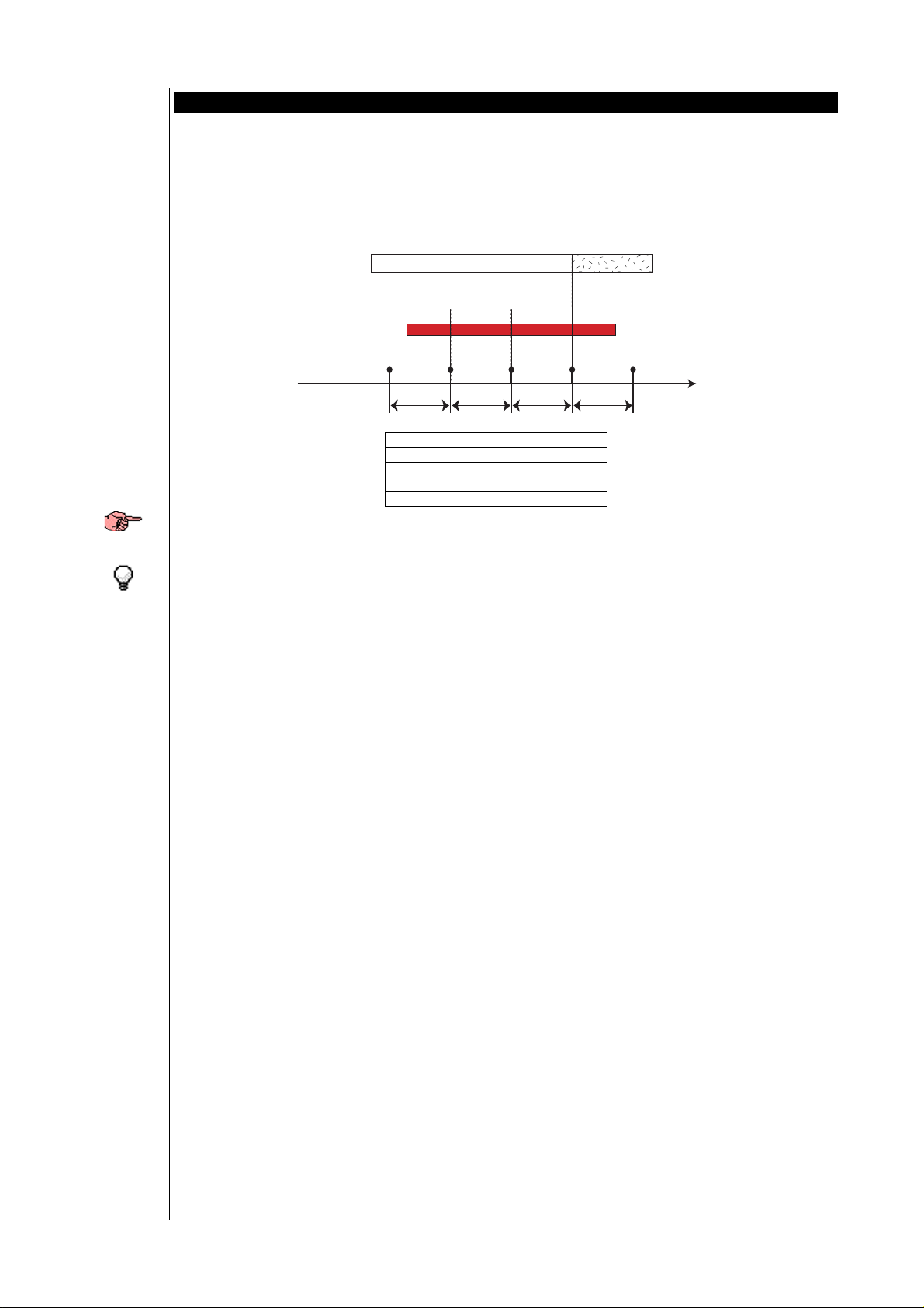
Alarms
Alarm events per
hour
10 DIAGNOSTICS
“Ech 200” can perform full systems diagnostics and signal a series of alarms.
Alarm trigger and reset modes are set using parameters Pa A01 – Pa A26.
For some alarms the signal will not be given for a certain amount of time, determined by a parameter.
For some alarms the number of alarm events is counted: if the number of alarm events in the past hour exceeds a certain
threshold set by a parameter, the alarm will switch from automatic to manual reset.
Alarms are sampled every 225 seconds;
Example: if the number of events/hour is set to 3, the duration of an alarm must fall between 2*225 seconds and 3*225
seconds for the alarm to be switched from automatic to manual reset.
A M
123
Alarm
Sampling
225 s 225 s 225 s 225 s
Time
A: Automatic reset
M: Manual reset
Alarm: alarm
Sampling: alarm sampling
Time: time
If an alarm is triggered more than once within one sampling period (225 seconds), only one alarm will be counted.
Alarms with manual reset are reset by pressing the ON-OFF button and releasing.
Manual reset shuts down corresponding loads and requires an operator to intervene (reset the alarm using the ON-OFF
control).
Manual reset alarms are used mainly to identify problems which could result in damage to the system.
10.1 List of alarms
When an alarm is triggered, two things occur:
• The corresponding loads are shut down
• The alarm appears on the keyboard display
The alarm message consists of a code with the format “Enn” (where nn is a 2-digit number identifying the type of alarm,
such as: E00, E25, E39….).
All possible alarms are listed in the table below, along with their codes and the corresponding loads that will be shut
down:
ECH 200 BD
41/76
Page 42

A
Table of alarms
E00 Remote Off Triggered by the
E01 High pressure
(digital)
E02 Low pressure
(digital)
E03 Thermal switch
protection
compressor 1
E04 Thermal switch
protection
condenser fan
E05 Anti-freeze Active if analogue
digital input
configured as
“Remote ON-OFF ”
(refer to digital
inputs)
Triggered by digital
input ID1 (refer to
digital inputs)
Triggered by digital
input ID2 (refer to
digital inputs);
Triggered by the
digital input
configured as
“Compressor 1
thermal switch” (refer
to digital inputs);
Triggered by the
digital input
configured as “Fan
thermal switch” (refer
to digital inputs);
probe AI2 (refer to
analogue inputs) is
configured as an antifreeze probe (Pa H06
= 1);
Triggered when
probe AI2 detects a
value below Pa A11;
BY PASS RESET
Automatically
timer Pa A01
after a
compressor is
turned on or
the 4-way valve
(reversing valve)
is reversed.
Inactive during
defrosting if Pa
24=0.
timer Pa A07
after
compressor is
turned on.
timer Pa A10
after Ech 200 is
turned on using
the On-OFF key
(refer to
keyboard) or by
a digital ON-
OFF input (refer
to digital
inputs).
reset unless
alarm events per
hour reaches
the value of
parameter Pa
A02, after which
manually reset;
Automatically
reset unless
alarm events per
hour reaches
the value of
parameter Pa
A08, after which
manually reset;
reset unless
alarm events per
hour reaches
the value of
parameter Pa
A09, after which
manually reset;
Goes off if AI2
detects a value
greater than Pa
A11 + Pa A12;
Automatically
reset unless
alarm events per
hour reaches
the value of
parameter Pa
13, after which
reset
COMPRESSOR 1 COMPRESSOR 2 EXTERNAL
OFF OFF OFF OFF OFF OFF OFF
OFF OFF Always manually
OFF OFF OFF OFF Inactive during
OFF Inactive during
OFF OFF OFF OFF Automatically
OFF OFF OFF Inactive during
FAN
BLOCCO UTENZE CODE SIGNAL DESCRIPTION
INTERNAL
FAN
PUMP ELECTRICAL
HEATER 1
ELECTRICAL
HEATER 2
ECH 200 BD
42/76
Page 43

COMPRESSOR 1 COMPRESSOR 2 EXTERNAL
BLOCCO UTENZE CODE SIGNAL DESCRIPTION
FAN
INTERNAL
FAN
PUMP ELECTRICAL
HEATER 1
ELECTRICAL
HEATER 2
BY PASS RESET
manually reset;
E06 Probe AI2 fault Triggered if probe
OFF OFF OFF OFF OFF OFF OFF
AI2, configured as an
analogue input,
shorts or is cut off or
probe limits are
exceeded (-50°C..
100°C).
E07 Probe AI3 fault Triggered if probe
OFF OFF OFF OFF OFF OFF OFF
AI3, configured as an
analogue input,
shorts or is cut off or
probe limits are
exceeded (-50°C..
100°C).
E13 Thermal switch
protection
compressor 2
Triggered by the
digital input
configured as
“Compressor 2
thermal switch” (refer
to digital inputs);
OFF Inactive during
timer Pa A07
after
compressor is
turned on.
Automatically
reset unless
alarm events per
hour reaches
the value of
parameter Pa
A08, after which
manually reset;
E40 Probe AI1 fault Triggered if probe
OFF OFF OFF OFF OFF OFF OFF
AI1, configured as an
analogue input,
shorts or is cut off or
probe limits are
exceeded (-50°C..
E41 Flow switch Triggered if the
100°C).
digital input
configured as “flow
switch” (refer to
digital inputs)
remains active for an
amount of time equal
to Pa A04;
OFF OFF OFF OFF
3
Inactive during
timer Pa A03
after pump
(hydraulic
pump) is turned
on
Goes off if the
digital input
configured as
“flow switch”
(refer to digital
inputs) remains
inactive for an
amount of time
equal to Pa A05;
Automatically
reset unless
alarm events per
hour reaches
the value of
parameter Pa
A06, after which
manually reset;
E42 Probe AI4 fault Triggered if probe OFF OFF OFF OFF OFF OFF OFF
ECH 200 BD
43/76
Page 44

COMPRESSOR 1 COMPRESSOR 2 EXTERNAL
AI4, configured as an
analogue input,
shorts or is cut off or
probe limits are
exceeded (-50°C..
100°C).
E43 Anti-freeze alarm
E45 Configuration
E46 Over-temperature Triggered if probe
3
Only if manually reset
Outputs defined as capacity steps will be off if there is an alarm for the compressor to which they belong.
(water-water
machine with gas
reversal)
error
Active if probe AI3 is
configured as an anitfreeze probe for
water-water machines
with gas reversal
(refer to analogue
inputs)
Triggered if probe
AI3 detects a value
below Pa A11
If AI1 is configured as
a request for heating
digital input and AI2
as a request for
cooling input (refer
to analogue inputs),
the alarm will be
triggered if both
inputs are active.
AI1 (refer to
analogue inputs) has
a value over Pa A25
for an amount of
time in excess of Pa
A26;
OFF OFF Goes off if
OFF OFF OFF OFF OFF OFF OFF
OFF OFF
BLOCCO UTENZE CODE SIGNAL DESCRIPTION
FAN
INTERNAL
FAN
PUMP ELECTRICAL
HEATER 1
ELECTRICAL
HEATER 2
BY PASS RESET
Automatically
temperature
detected by AI3
exceeds Pa A11
+ Pa A12.
reset unless
alarm events per
hour reaches
the value of
parameter Pa
A13, after which
manually reset;
ECH 200 BD
44/76
Page 45

Digital alarms
Analogue alarms
The tables below list alarms by type (digital or analogue).
10.1.1 TABLE OF DIGITAL ALARMS:
Alarm name Bypass trigger event Bypass time Trigger
High pressure alarm None absent absent absent Manual reset
Low pressure alarm A compressor coming
Flow switch alarm Pump coming on Pa A03 Pa A04 Pa A05 Pa A06
Thermal switch
compressor 1.2
Thermal switch fan None absent absent absent Pa A13
10.1.2 TABLE OF ANALOGUE ALARMS:
Alarm name Event Time.
Anti-freeze alarm On Off, input
Low condensation
pressure/temperature
alarm
High condensation
pressure/temperature
alarm
Over-temperature
alarm
External anti-freeze
alarm
on in the circuit or
reversal of 4-way
valve
Compressor coming
on
in heating
mode, remote
on off
Compressor
turned on or
reversal of 4way valve
None absent Pa A14 Pa A15
None Trigger
None None Pa A11 Pa A12
Pa A01 absent absent Pa A02
Pa A07 absent absent Pa A08
Bypass
Pa A10 Pa A11 Pa A12
Par A16 Pa A17 Pa A18
duration
must
exceed
Pa A26
Trigger set
point
Pa A25 Pa A12
duration
Hystere
sis
positive
positive
negativ
e
negativ
e
positive
Deactivation
duration
N. alarm
events/hour
Pa A13 AI2 if configuration
Pa A19 Probe configured for
Manual reset Probe configured for
Automatic
reset
Pa A13 AI3 if Pa H07= 4
N. alarm
events/hour
Regulation probe
parameter Pa H06 = 1,
otherwise alarm is
inactive
condensation control
condensation control
AI1
Page 46

Pa G01
Pa G02
Pa H01
Pa H02
Pa H03
Pa H04
Pa H05
Pa H06
Pa H07
Pa H08
Pa H09
Pa H10
Pa H11
Pa H12
Pa H13
Pa H14
Pa H15
Pa H16
Pa H17
Pa H18
Pa H19
Pa H20
11 PARAMETERS
Parameters make the ”Ech 200” a fully configurable device.
They may be modified through:
• instrument keyboard
• copy card
• personal computer (with a suitable connection and “Param manager” software)
11.1 Description of parameters
We will now look at parameters in detail, divided by category.
11.1.1 Configuration parameters
Determine the features of the machine. If one or more parameters in this category are modified, the controller must be
switched off after the modification and switched on again to ensure correct operation.
Values marked with a (*) are valid only for Ech 2xxB
“Cooling” set point
Allows the set point to be set on “cooling” mode.
“Heating” set point
Allows the set point to be set on “heating” mode
Maximum set point during “heating”
Upper limit on set point in “heating” mode
Minimum set point during “heating”
Lower limit on set point in “heating” mode
Maximum set point during “cooling”
Upper limit on set point in “cooling” mode
Minimum set point during cooling
Lower limit on set point in “cooling” mode
AI1 Configuration
Used to configure analogue input Al1
• 0= No probe
• 1= Inlet water/air analogue input
• 2= Heating request digital input
• 3= Regulation algorithm request digital input
• 4= Differential NTC input
• 5= On remote keyboard (*)
AI2 Configuration
• 0= No probe
• 1= Outlet water/antifreeze/inlet air analogue input
• 2= Cooling request digital input
• 3= Anti-freeze alarm digital input
AI3 Configuration
• 0= No probe
• 1= Condensation control analogue input
• 2= 4...20 mA condensation input
• 3= 4...20 mA dynamic set point input
• 4= Antifreeze analogue input for water-water machines with gas reversal
• 5= Regulation algorithm input in “heating” mode for water-water machines with manual reversal
AI4 Configuration
• 0= No probe
• 1= Condensation control NTC input
• 2= Multifunctional digital input
• 3= Outdoor temperature NTC input
• 4= Antifreeze analogue input for water-water machines with gas reversal
Bottom of scale pressure value
Maximum inlet value; determines the value corresponding to a current of 20 mA
Polarity of digital input ID1
Polarity of digital input ID2
Polarity of digital input ID3
Polarity of digital input ID4
Polarity of digital input ID5
• 0= Active when contact closed
• 1= Active when contact open
Polarity of analogue input Al1
Polarity of analogue input Al2
Polarity of analogue input Al4
If configured as digital inputs:
• 0= Active when contact closed
• 1= Active when contact open
Configuration of digital input ID3
Configuration of digital input ID4
Configuration of digital input ID5
• 0= Compressor 1 thermal switch
• 1= Fan thermal switch
• 2= Flow switch
• 3= Remote Heat/Cool
• 4= Remote ON-OFF
Page 47

Pa H21
Pa H22
Pa H23
Pa H24
Pa H25
Pa H26
Pa H27
Pa H28
Pa H29
Pa H30
Pa H31
Pa H32
Pa H33
Pa H34
Pa H35
Pa H36
Pa H37
Pa H38
Pa H39
Pa H40
Pa H42
Pa H41
Pa H43
Pa H44
Pa H45
Pa H46
Pa H47
Pa H48
• 5= Compressor 2 thermal switch
• 6= Request for second compressor (step)
Configuration of AI4 if configured as a digital input (Pa H08=2)
• 0= Compressor thermal switch
• 1= Fan thermal switch
• 2= Flow switch
• 3= Remote Heat/Cool
• 4= Remote ON-OFF
• 5= Compressor 2 thermal switch
• 6= Request for second compressor (step)
Configuration of output NO2
• 0= Pump
• 1= Internal fan step 1
Configuration of output relay NO3
• 0= Reversal
• 1= Internal fan step 3
• 2= second compressor (step)
Configuration of output relay NO4
• 0= Anti-freeze electrical heaters
• 1= Internal fan step 2
• 2= Boiler
Optional analogue output configuration
• 0= open Collector output for second compressor
• 1= fan speed 4-20 mA output
• 2= fan speed 0-10 V output
Configuration of serial protocol (not used)
• 0= Standard
• 1= INVENSYS
Selection of operating mode
May be used to select which input determines operation in Heating/Cooling mode
• 0= Selection from keyboard
• 1= Selection from digital input
• 2= Selection from analogue input (probe Al4)
Presence of heat pumpt
• 0= Heat pump absent
• 1= Heat pump present
Heating mode set point
If mode selecton from analogue input is enabled, this is the value of Al4 below which the control will switch to “heating”
mode
Mode selection differential
If mode selection from analogue input is enabled, this is the temperature differential for switching to “cooling” mode
Enable dynamic set point
Enables the function
• 0= Dynamic set point disabled
• 1= Dynamic set point enabled
Dynamic set point offset in
The maximum value that may be added to the set point in “cooling” mode
Dynamic set point offset in heating mode
The maximum value that may be added to the set point in “heating” mode
Outdoor temperature dynamic set point in cooling mode
The temperature above which the set point offset is zero in cooling mode.
Outdoor temperature dynamic set point in heating mode
The temperature above which the set point offset is zero in heating mode.
Outdoor temperature dynamic set point differential in cooling mode
May be used to set the differential for the outdoor temperature below which the maximum set point offset applies
Outdoor temperature dynamic set point differential in heating mode
May be used to set the differential for the outdoor temperature above which the maximum offset applies.
Reversing valve polarity
• relay ON in cool
• relay ON in heat
Offset AI1,
Offset AI2,
Offset AI4
These parameters may be used to compensate the error that may occur between the temperature reading and the actual
temperature or pressure.
Offset AI3
This parameter may be used to compensate the error that may occur between the temperature or pressure reading and
the actual temperature or pressure.
mains frequency
• 0= mains frequency 50 Hz
• 1= mains frequency 60 Hz
Family serial address,
Device serial address
May be used to select serial address. Both normally 0.
User password
May be used to enter a parameter for access to level two parameters.
Copy card write password
The password that must be entered to copy parameters to the copy card.
Number of compressors per circuit
• 1= 1 compressor
cooling mode
ECH 200 BD
47/76
Page 48

Pa H49
Pa H50
Pa H51
Pa H52
Pa H53
Pa H54
Pa H55
Pa H56
Pa H57
• 2= 2 compressors (or 2 steps)
Enable pressure / temperature-based operation
• 0= parameters Pa H07=0 (probe Al3 absent) and Pa F01 = 3 (functioning in response to request from
compressor) are forced.
• 1= temperature-based operation; parameters Pa H07,Pa F01 are forced to: Pa H07= 1 (probe Al3 temperature),
Pa F01= 3 (functioning in response to request from compressor).
• 2= pressure-based operation; parameters Pa H07, Pa F01 are forced to: Pa H07= 2 (probe ST3 pressure), F01= 0
(proportional functioning).
• 3= no constraints are set on parameters
Compressor on sequence
• 0= compressors come on on the basis of number of hours of operation (balancing hours of operation)
• 1= compressor 1 is turned on first, followed by compressor (or capacity step) 2 (unvaried sequence).
Compressor 2 or capacity step polarity
• 0= relay ON if compressor 2/capacity step ON
• 1= relay ON if compressor 2/ capacity step OFF
selection of degrees °C or °F
• 0= degrees °C
• 1= degrees °F
SET display for air’/air macchine
In order to facilitate the user interface in the air/air version, the set associated with the selected mode is normally
displayed by setting th parameter PS H53
Customer Code 1
A number between 0 and 999 that the user can assign for internal use
Customer Code 2
A number between 0 and 999 that the user can assign for internal use
Polarity of relay alarm
• 0 = output is active (closed contact) when an alarm is active and when the machine is switched off.
• 1 = in the same conditions, the contact is open
Enable relay alarm in off position
• 0 =
• 1 = alarm output enabled in OFF or standby
alarm output not enabled in OFF or standby
Pa C01
Pa C02
Pa C03
Pa C04
Pa C05
Pa C06
Pa C07
Pa C08
Pa C09
Pa C10
Pa C11
Pa C12
Pa C13
Pa F01
Pa F02
Pa F03
Pa F04
Pa F05
Pa F06
11.1.2 Compressor parameters (CP)
OFF-ON safety time
The minimum amount of time that must pass between turning off the compressor and turning it on again. Expressed in
tens of seconds.
ON-ON safety time
The minimum amount of time that must pass between turning the compressor on and turning it on again. Expressed in
tens of seconds.
Cooling regulation algorithm hysteresis
May be used to select intervention differential in cooling mode.
Heating regulation algorithm hysteresis
May be used to select intervention differential in heating mode.
Regulation algorithm step intervention differential
May be used to set a temperature differential in relation to the set point beyond which the second step is activated.
Compressor 1 - compressor 2 (step) on interval
May be used to set a delay between turning on of two steps.
Compressor 1 - compressor 2 (step) off interval
May be used to set a delay between turning off of two steps.
Enables the Adaptive function.
0=disabled function; 1=enabled function;
Set block in Cooling mode
Enables to configure a set point that disables the Adaptive function in Cooling mode.
Set block in Heating mode
Enables to configure a set point that disables the Adaptive function in Heating mode.
Offset constant
Constant value of Adaptive algorithm
Reset time for increases
Function proportional constant
Value used to multiply the difference between the minimum and actual running time.
11.1.3 Fan control parameters (FAN)
Fan output configuration
• 0: proportional condensation control TK output
• 1: ON-OFF TK output
• 2: anti-freeze electrical heater output for water-water machines with gas reversal
• 3: TK ON-OFF output on compressor
Fan pick-up time
Time for which fan runs at maximum speed after starting up. Expressed in seconds/10.
Fan phase shift
May be used to adapt output to various types of fans.
Impulse duration of triac on
May be used to vary the length of the impulse from the triac.
Functioning in response to compressor request
• 0: if compressor is off, fan is off
• 1: condensation control independent of compressor
Minimum speed during cooling
ECH 200 BD
48/76
Page 49

Pa F07
Pa F08
Pa F09
Pa F10
Pa F11
Pa F12
Pa F13
Pa F14
Pa F15
Pa F16
Pa F17
Pa F18
Pa F19
Pa F20
Pa F21
Pa F22
Pa F23
Pa F24
Pa F25
Minimum value of proportional fan control during cooling. Expressed as a percentage of the maximum permitted voltage,
from 0 to 100%,.
Maximum silent speed during cooling
Maximum value of proportional fan control during cooling. Expressed as a percentage of the maximum permitted voltage,
from 0 to 100%,.
Minimum fan speed temperature/pressure set point during cooling
Condensation pressure/temperature value below which the fan runs at minimum cooling speed.
Proportional band during cooling
Temperature/pressure differential corresponding to change from minimum to silent maximum fan speed during cooling.
Cut-off differential
Condensation temperature/pressure differential within which fan continues to run at low speed.
Cut-off hysteresis.
Condensation temperature/pressure differential for fan cut-off.
Cut-off bypass time
Determines the amount of time after fan start-up during which compressor cut-off is excluded. Expressed in seconds.
Maximum speed during cooling
May be used to set a speed step corresponding to a given temperature/pressure value during cooling.
Maximum fan speed temperature/pressure set point in cooling mode
Condensation temperature/pressure value corresponding to the fan speed set for par. F13.
Minimum speed during heating
Minimum proportional fan control value in heating mode. Expressed as a percentage of the maximum permitted voltage,
from 0 to 100%,.
Maximum silent speed during heating
Maximum value of proportional fan control during heating. Expressed as a percentage of the maximum permitted voltage,
from 0 to 100%,.
Minimum fan speed temperature/pressure set point during heating
Condensation temperature/pressure value above which the fan operates at minimum speed in heating mode.
Proportional band during heating
Temperature/pressure differential corresponding to a change from minimum to maximum silent fan speed during heating.
Maximum speed during heating
May be used to set a speed step corresponding to a given temperature/pressure value during heating.
Maximum fan speed temperature/pressure set point during heating
Condensation temperature/pressure value corresponding to the fan speed set for par. F19.
Internal fan step differential
May be used to set a temperature differential between one step of fan control and the next for internal fan control.
Internal fan step hysteresis
May be used to set a hysteresis for each fan control step cut-off.
Not used
Not used
Preventilation in cooling mode
May be used to set a preventilation time in cooling mode before the compressor is turned on.
Pa A01
Pa A02
Pa A03
Pa A04
Pa A05
Pa A06
Pa A07
Pa A08
Pa A09
Pa A10
Pa A11
Pa A12
Pa A13
11.1.4 Alarm parameters (ALL)
Low pressure pressure switch bypass time.
Determines the delay between starting up the compressor and starting up the low pressure digital alarm diagnostics.
Expressed in seconds.
Low pressure alarm events per hour
Used to set the number of low pressure digital alarm events per hour beyond which the system will switch from automatic
reset to manual reset.
Bypass flow switch after pump on
Determines the delay between activation of the hydraulic pump and activation of the flow switch alarm diagnostics.
Expressed in seconds.
Duration of active flow switch input
May be used to set the amount of time for which the flow switch digital input must remain active to generate a flow
switch alarm. The timer starts after the flow switch by-pass time. Expressed in seconds.
Duration of inactive flow switch input
May be used to set the time for which the flow switch digital input must remain inactive to be included in the
corresponding alarm. Expressed in seconds.
Number of flow switch alarms/hour
May be used to set the number of flow switch digital alarms per hour after which the alarm is switched from automatic to
manual reset. When this occurs, the hydraulic pump is deactivated.
Compressor thermal switch bypass following compressor on
Determines the delay between compressor activation and activation of the compressor thermal switch digital diagnostics
alarm. Expressed in seconds.
Compressor 1/2 thermal switch alarm events per hour
May be used to set a number of compressor thermal switch alarm events per hour beyond which the alarm is switched
from automatic to manual reset..
Fan thermal switch alarm events per hour
May be used to set a number of fan thermal switch alarm events per hour beyond which the alarm is switched from
automatic to manual reset.
Anti-freeze alarm by-pass
Determines the delay between turning on the machine and activation of the anti-freeze alarm; it is enabled only in the
heating mode. Expressed in minutes.
Anti-freeze
May be used to set the temperature below which the anti-freeze alarm is triggered.
Anti-freeze alarm differential
May be used to set the anti-freeze alarm differential.
Anti-freeze alarm events per hour
May be used to set a number of anti-freeze alarm events per hour beyond which the alarm is switched from automatic to
manual reset.
alarm set point
ECH 200 BD
49/76
Page 50

Pa A14
Pa A15
Pa A16
Pa A17
Pa A18
Pa A19
Pa A20
Pa A21
Pa A22
Pa A23
Pa A24
Pa A25
Pa A26
Pa P01
Pa P01
Pa P02
Pa P03
Not used
Not used
Not used
Not used
Not used
Not used
Machine out of coolant differential
If the difference between the absolute value of Al2 and is lower than this parameter when in heating and higher when in
cooling, the machine out of coolant timer will start.
Machine out of coolant bypass
Determines the delay between the turning on of the first compressor in the corresponding cooling circuit and activation of
the machine out of coolant alarm diagnostics. Expressed in minutes.
Machine out of coolant duration
Determines the amount of time beyond which the machine out of coolant alarm will be triggered.
Machine out of coolant alarm activation
Enables machine out of coolant alarm
Enable low pressure alarm during defrosting
Enables the minimum alarm during defrosting. If 0, the low pressure alarm is disabled during defrosting.
Over-temperature set point
Temperature value Al1 above which the over-temperature alarm E46 is triggered.
Over-temperature ON duration
Determines the duratoni of the condition Al1>A25 beyond which alarm E46 is triggered.
Pump parameters (PUP)
Pump operating mode
May be used to determine pump operating mode:
• 0=continuous operation
• 1=operation in response to a request from the regulation algorithm
• 2=cyclic operation
Pump or fan operating mode
May be used to determine pump or fan operating mode:
• 0=(pump) continuous operation | (fan) the fan is never switched off
• 1= (pump) operation in response to a request from regulation algorithm | (fan) the fan is turned off with the
Delay between pump ON and compressor ON
May be used to set a delay between starting a pump and starting a compressor. Expressed in seconds.
Delay between compressor OFF and pump OFF
May be used to set a delay between turning off a compressor and turning off a pump. Expressed in seconds.
compressor
Pa r01
Pa r02
Pa r03
Pa r04
Pa r05
Pa r06
Pa r07
Pa r08
Pa r09
Pa r10
Pa r11
Pa r12
Pa r13
11.1.5 Anti-freeze/boiler parameters (FRO)
Configuration of electrical heaters in defrost mode
Determines electrical heater operation during defrosting
• 0=come on only in response to a request from the regulation algorithm
• 1=always on during defrosting
Configuration of electrical heaters on in cooling mode
Determines electrical heater operation in cooling mode
•
0=off during cooling
• 1=on during cooling (in response to anti-freeze electrical heater regulation algorithm)
Configuration of electrical heaters on in heating mode
Determines electrical heater operation in heating mode
• 0=off during heating
• 1= on during heating (in response to anti-freeze electrical heater regulation algorithm)
Configuration of anti-freeze electrical heater control probe in heating mode
Determines electrical heater control probe in heating mode
• 0= Controls on the basis of probe Al1
• 1= Controls on the basis of probe Al2
Configuration of anti-freeze electrical heater control probe in cooling mode
Determines electrical heater control probe in cooling mode
• 0= Controls on the basis of probe Al1
• 1= Controls on the basis of probe Al2
Configuration of electrical heaters when OFF or on stand-by
Determines the status of electrical heaters when the instrument is OFF or on stand-by
• 0=Always off when OFF or on stand-by
• 1=On when OFF or on stand-by (in response to anti-freeze electrical heater control algorithm)
Set point of anti-freeze electrical heaters in heating mode
Temperature value below which anti-freeze electrical heaters come on in heating mode.
Set point of anti-freeze electrical heaters in cooling mode
Temperature value below which anti-freeze electrical heaters come on in cooling mode.
Maximum set point of anti-freeze electrical heaters
Determines the maximum setting of the anti-freeze electrical heater set point.
Minimum set point of anti-freeze electrical heaters
Determines the minimumsetting of the anti-freeze electrcial heater set points.
Anti-freeze heater hysteresis
Anti-freeze electrical heater control algorithm hysteresis.
Set point of external anti-freeze electrical heaters
Temperature below which external anti-freeze electrical heaters come on.
Outdoor temperature set point
The temperature below which the boiler is turned on and the heat pump is turned off.
for boiler on
ECH 200 BD
50/76
Page 51
Pa r14
Pa r15
Pa d01
Pa d02
Pa d03
Pa d04
Pa d05
Pa d06
Pa d07
Pa d08
Pa d09
Pa d10
Pa d11
Pa d12
Pa d13
Boiler off differential
Boiler off differential. If outdoor temperature exceeds Pa r14+Pa r13, the boiler will be turned off and the heat pump will
be turned on.
Supplementary electrical heater control
If this parameter =1 the electrical heaters have the double function of anti-freeze electrical heaters and supplementary
heaters
Otherwise (Pa r15=0) the electrical heaters have only the anti-freeze function
11.1.6 Defrost parameters (DFR)
Defrost enabled
0= defrost function enabled
1= defrost function enabled
Defrost start temperature/pressure
Temperature/pressure below which the defrost cycle is started.
Defrost interval (response time)
Duration for which probe remains below defrost start temperature/pressure. Expressed in minutes.
Defrost end temperature/pressure
Temperature/pressure above which defrost ends.
Maximum defrost time (time-out)
Maximum duration of defrosting. Expressed in minutes.
Compressor-reversing valve wait time (anti-bleeding)
Wait time between compressor going off and reversal of the 4-way valve at the beginning of the defrost cycle.
Drip time
Wait time at the end of the defrost cycle between turning off the compressor and reversing the 4-way valve.
Temperature at which defrost starts if Pa H49= 1
Temperature below which the defrost cycle is started.
Temperature at which defrost ends if Pa H49=1
Temperature above which the defrost cycle is ended.
Enable defrost compensation
See compensation temperature at defrost start
Defrost temperature/pressure compensation offset
See compensation temperature at defrost start
Defrost temperature/pressure compensation set point
See compensation temperature at defrost start
Defrost temperature/pressure compensation delta
See compensation temperature at defrost start
Configuration
parameters
11.2 Table of parameters
All ”Ech 200” parameters are listed in the table below.
The parameters in gray are valid only for the models Ech 2xxB
CONFIGURATION PARAMETERS*
Par. Description Limits Unit of
measurement
Pa G01 “Cooling” set point
Pa G02 “Heating” set point
Pa H01 Maximum set point during heating Pa H02 ÷ 90.0 °C
Pa H02 Minimum set point during heating -40.0 ÷ Pa H01 °C
Pa H03 Maximum set point during cooling Pa H04 ÷ 90.0 °C
Pa H04 Minimum set point during cooling -40.0 ÷ Pa H03 °C
Pa H05 AI1 Configuration 0 ÷ 5 Num
Pa H06 AI2 Configuration 0 ÷ 3 Num
Pa H07 AI3 Configuration 0 ÷ 5 Num
Pa H08 AI4 Configuration 0 ÷ 4 Num
Pa H09 Bottom of scale pressure value 0-350 kPa*10
Pa H10 Polarity ID1 0 ÷ 1 Flag
Pa H11 Polarity ID2 0 ÷ 1 Flag
Pa H12 Polarity ID3 0 ÷ 1 Flag
Pa H13 Polarity ID4 0 ÷ 1 Flag
Pa H14 Polarity ID5 0 ÷ 1 Flag
Pa H15 Polarity AI1 0 ÷ 1 Flag
Pa H16 Polarity AI2 0 ÷ 1 Flag
Pa H17 Polarity AI4 0 ÷ 1 Flag
Pa H18 Configuration ID3 0 ÷ 6 Num
Pa H19 Configuration ID4 0 ÷ 6 Num
Pa H20 Configuration ID5 0 ÷ 6 Num
Pa H21 Configuration Al4 if digital input 0 ÷ 6 Num
Pa H22 Configuration relay 2 0 ÷ 1 Num
Pa H23 Configuration relay 3 0 ÷ 2 Num
Pa H24 Configuration relay 4 0 ÷ 2 Num
Pa H25 Optional analogue output configuration 0 ÷ 2 Num
Pa H26 Configuration of serial protocol (not used) 0 ÷ 1 Num
Pa H27 Selection of operating mode 0 ÷ 2 Num
ECH 200 BD
51/76
Page 52

Table of
compressor
parameters (CP)
Table of
parameters: fan
control
parameters (FAN)
Pa H28 Presence of heat pumpt 0 ÷ 1 Flag
Pa H29 Heating mode set point 0 ÷ 255 °C
Pa H30 Mode selection differential 0 ÷ 25.5 °C
Pa H31 Enable dynamic set point 0 ÷ 1 Flag
Pa H32 Dynamic set point offset in cooling mode -12.7 ÷ 12.7 °C
Pa H33 Dynamic set point offset in heating mode -12.7 ÷ 12.7 °C
Pa H34 Outdoor temperature set point in cooling mode 0 ÷ 255 °C
Pa H35 Outdoor temperature set point in heating mode 0 ÷ 255 °C
Pa H36 Outdoor temp. dynamic set point differential in cooling -25.5 ÷ 25.5 °C
Pa H37 Outdoor temp. dynamic set point differential in heating -25.5 ÷ 25.5 °C
Pa H38 Reversing valve polarity 0 ÷ 1 Flag
Pa H39 Offset AI1 -12.7 ÷ 12.7 °C
Pa H40 Offset AI2 -12.7 ÷ 12.7 °C
Pa H41 Offset AI3 -127 ÷ 127 °C/10 - kPa*10
Pa H42 Offset AI4 -12.7 ÷ 12.7 °C
Pa H43 Mains frequency 0 ÷ 1 Flag
Pa H44 Family serial address 0 ÷ 14 Num.
Pa H45 Device serial address 0 ÷ 14 Num.
Pa H46 User password 0 ÷ 255 Num.
Pa H47 Copy card write password 0 ÷ 255 Num.
Pa H48 Number of compressors per circuit 1 ÷ 2 Num.
Pa H49 Enable pressure/temperature based operation 0÷3 Num.
Pa H50 Compressor on sequence 0÷1 Num.
Pa H51 Compressor 2 or capacity step polarity 0÷1 Num.
Pa H52 Selection of degrees °C or °F 0÷1 Num.
Pa H53 SET display for air’/air macchine 0÷1 Num.
Pa H54 Customer Code 1 0÷999 Num.
Pa H55 Customer Code 2 0÷999 Num.
Pa H56 Polarity of relay alarm 0÷1 Num.
Pa H57 Enable relay alarm in off position 0÷1 Num.
• If parameters in this category are modified, the controller must be turned off after the modification and turned on
again to guarantee correct functioning.
COMPRESSOR PARAMETERS
Par. Description Limits Unit of
Pa C01 ON-OFF safety time 0 ÷ 255 Seconds*10
Pa C02 ON-ON safety time 0 ÷ 255 Seconds*10
Pa C03 Cooling regulation algorithm hysteresis 0 ÷ 25.5 °C
Pa C04 Heating regulation algorithm hysteresis 0 ÷ 25.5 °C
Pa C05 Regulation algorithm step intervention differential 0 ÷ 25.5 °C
Pa C06 Compressor 1 – compressor 2 (step) on interval 0 ÷ 255 Seconds
Pa C07 Compressor 1 – compressor 2 (step) off interval 0 ÷ 255 Seconds
Pa C08 Start function on units without accumulation tank 0 ÷ 1 Flag
Pa C09 Set block in Cooling mode 0 ÷ 255 °C
Pa C10 Set block in Heating mode 0 ÷ 255 °C
Pa C11 Offset constant 0 ÷ 25.5 °C
Pa C12 Reset time for increases 0 ÷ 255 Seconds*10
Pa C13 Proportional Part Offset Coefficient 0 ÷ 25.5 °C/(10*sec)
FAN PARAMETES
Par. Description Limits Unit of
Pa F01 Fan output configuration 0 ÷ 3 Num.
Pa F02 Fan pick-up time 0 ÷ 255 Seconds/10
Pa F03 Fan phase shift 0 ÷ 100 µs*200
Pa F04 Impulse duration of triac on 0 ÷ 255 µs*200
Pa F05 Functioning in response to compressor request 0 ÷ 1 Flag
Pa F06 Minimum speed during cooling 0 ÷ 100 %
Pa F07 Silent speed during cooling 0 ÷ 100 %
Pa F08 Minimum fan speed temperature/pressure set point during
cooling
Pa F09 Prop. band during cooling 0 ÷ 255 °C/10–kPa*10
Pa F10 Cut-off differential 0 ÷ 255 °C/10–kPa*10
Pa F11 Cut-off hysteresis 0 ÷ 255 °C/10–kPa*10
Pa F12 Cut-off bypass time 0 ÷ 255 Seconds
Pa F13 Maximum speed during cooling 0 ÷ 100 %
Pa F14 Maximum fan speed temperature/pressure set point in
cooling mode
Pa F15 Minimum speed during heating 0 ÷ 100 %
Pa F16 Silent speed during heating 0 ÷ 100 %
Pa F17 Minimum fan speed temperature/pressure set point during
heating
Pa F18 Proportional band during heating 0 ÷ 255 °C/10–kPa*10
Pa F19 Maximum speed during heating 0 ÷ 100 %
-500 ÷ 800 °C/10–kPa*10
-500 ÷ 800 °C/10–kPa*10
-500 ÷ 800 °C/10–kPa*10
measurement
measurement
ECH 200 BD
52/76
Page 53

Table of
parameters: alarm
parameters (ALL)
Table of
parameters: pump
parameters (PUP)
Table of
parameters: Anti-
freeze/boiler
parameters (FRO)
Table of
parameters:
defrost
parameters (DFR)
Pa F20 Maximum fan speed temperature/pressure set point during
heating
Pa F21 Internal fan step differential 0 ÷ 25.5 °C
Pa F22 Internal fan step hysteresis 0 ÷ 25.5 °C
Pa F23 Not used / /
Pa F24 Not used / /
Pa F25 Preventilation in cooling mode 0 ÷ 255 Seconds
ALARM PARAMETERS
Par. Description Limits Unit of
Pa A01 Low pressure pressure switch bypass time after comp. on 0 ÷ 255 Seconds
Pa A02 Low pressure alarm events per hour 0 ÷ 255 Num
Pa A03 Bypass flow switch after pump on 0 ÷ 255 Seconds
Pa A04 Duration of active flow switch input 0 ÷ 255 Seconds
Pa A05 Duration of inactive flow switch input 0 ÷ 255 Seconds
Pa A06 Number of flow switch alarm events per hour 0 ÷ 255 Num
Pa A07 Compressor thermal switch bypass following comp. on 0 ÷ 255 Seconds
Pa A08 Compressor 1/2 thermal switch alarm events per hour 0 ÷ 255 Num
Pa A09 Fan thermal switch alarm events per hour 0 ÷ 255 Num
Pa A10 Anti-freeze alarm bypass after ON-OFF 0 ÷ 255 Minutes
Pa A11 Anti-freeze alarm set point -127 ÷ 127 °C
Pa A12 Anti-freeze alarm hysteresis 0 ÷ 25.5 °C
Pa A13 Anti-freeze alarm events per hour 0 ÷ 255 Num
Pa A14 Not used / /
Pa A15 Not used / /
Pa A16 Not used / /
Pa A17 Not used / /
Pa A18 Not used / /
Pa A19 Not used / /
Pa A20 Machine out of coolant differential 0 ÷ 255 °C
Pa A21 Machine out of coolant bypass 0 ÷ 255 Minutes
Pa A22 Machine out of coolant duration 0 ÷ 255 Minutes
Pa A23 Machine out of coolant alarm activation 0 ÷ 1 Flag
Pa A24 Enable low pressure alarm during defrosting 0 ÷ 1 Flag
Pa A25 Over-temperature set point 0 ÷ 255 °C
Pa A26 Over-temperature ON duration 0 - 255 Seconds*10
-500 ÷ 800 °C/10–kPa*10
measurement
PUMP PARAMETERS
Par. Description Limits Unit of
Pa P01 Pump operating mode 0 ÷ 1 Num.
Pa P02 Delay between pump ON and compressor ON 0 ÷ 255 Seconds
Pa P03 Delay between compressor OFF and pump OFF 0 ÷ 255 Seconds
measurement
ANTI-FREEZE/BOILER PARAMETERS
Par. Description Limits Unit of
Pa r01 Configuration of electrical heaters in defrost mode 0 ÷ 1 Flag
Pa r02 Configuration of electrical heaters on in cooling mode 0 ÷ 1 Flag
Pa r03 Configuration of electrical heaters on in heating mode 0 ÷ 1 Flag
Pa r04 Configuration of anti-freeze electrical heater control probe
in heating mode
Pa r05 Configuration of anti-freeze electrical heater control probe
in cooling mode
Pa r06 Configuration of electrical heaters when OFF or on stand-by 0 ÷ 1 Flag
Pa r07 Set point of anti-freeze electrical heaters in heating mode Pa r09÷Pa r10 °C
Pa r08 Set point of anti-freeze electrical heaters in cooling mode Pa r09÷Pa r10 °C
Pa r09 Maximum set point of anti-freeze electrical heaters Pa r10÷127 °C
Pa r10 Minimum set point of anti-freeze electrical heaters -127÷Pa r09 °C
Pa r11 Anti-freeze heater hysteresis 0 ÷ 25.5 °C
Pa r12 Set point of external anti-freeze electrical heaters Pa r09÷Pa r10 °C
Pa r13 Outdoor temperature set point for boiler on -127 ÷ 127 °C
Pa r14 Outdoor temperature differential for boiler off 0 ÷ 25.5 °C
Pa r15 Enable supplementary electrical heaters 0 ÷ 1 Flag
0 ÷ 1 Flag
0 ÷ 1 Flag
measurement
DEFROST PARAMETERS
Par. Description Limits Unit of
Pa d01 Defrost enabled 0 ÷ 1 Flag
Pa d02 Defrost start temperature/pressure -500 ÷ 800 °C/10 - kPa*10
Pa d03 Defrost interval (response time) 0 ÷ 255 Minutes
Pa d04 Defrost end temperature/pressure -500 ÷ 800 °C/10 - kPa*10
measurement
ECH 200 BD
53/76
Page 54

Pa d05 Maximum defrost time 0 ÷ 255 Minutes
Pa d06 Compressor-reversing valve wait time 0 ÷ 255 Seconds
Pa d07 Drip time 0 ÷ 255 Seconds
Pa d08 Temperature at which defrost starts if Pa H49= 1 -50.0 ÷ 80.0 °C/10
Pa d09 Temperature at which defrost ends if Pa H49= 1 -500 ÷ 80.0 °C/10
Pa d10 Enable defrost compensation 0 ÷ 1 Flag
Pa d11 Defrost temperature/pressure compensation offset -255 ÷ 255 °C/10 - kPa*10
Pa d12 Defrost temperature/pressure compensation set point -127 ÷ 127 °C
Pa d13 Defrost temperature/pressure compensation delta -25.5 ÷ 25.5 °C
ECH 200 BD
54/76
Page 55

Current
transformer
12 TECHNICAL FEATURES
12.1 Technical information
Tipical Min. Max.
Power supply tension 12V~ 10V~ 14V~
Power supply frequency 50Hz/60Hz --- --Power 5VA --- --Isolation class 1 --- --Use environment temperature 25°C -10°C 60°C
Use environment humidity (non-condensing) 30% 10% 90%
Stocking environment temperature 25°C -20°C 85°C
Stocking environment humidity (non-condensing) 30% 10% 90%
12.2 Electromagnetic characteristic
Digital exits 120/240 V • n° 4 relais 2A ¼ hp 240V~; 1/8 hp 120V~
WARNING: The TOTAL current on relay must NOT exceed 8A
• 1 TRIAC 2 A
Exits 24 V~ • 1 TRIAC non optic insulation entry maximum 500 mA.
Analogue inputs • 3 temperature sensors, reading field -30°C ÷ 90°C;
• 1 configurable input: 4...20 mA transducer or temperature sensor,
reading field -30°C ÷ 90°C;
Digital inputs • n° 5 Voltage-free digital inputs
Terminals and connectors • 1 quick coupling 9-ways connector high voltage AWG 16-28
• 1 quick coupling 16-ways connector low voltage pitch 4,2, AWG 16-
28
• 1 5-ways p2,5 connector remote control and foreign key
scheduling, AWG 24-30
• 1 3-ways p2 3 connector remote keyboard or optional relay, AWG
22-30;
Display and led • 3 digit + sign;
• 5 red leds
Keys • 2 keys
Serials • n° 1 9600 serial
• n° 1 2400 serial (keyboard output)
Turn the power on to the instrument using an appropriate current transformer with the following features:
• Primary voltage: 230V~±10%; 110V~±10%
• Secondary voltage: 12V~
• Power supply frequency: 50Hz; 60Hz
• Power: 5VA;
12.3 Dimensions
• Dimensions: 76x34x58mm
• Container: PC+ABS plastic resin with V0 extinguishing classification
• Assembly: Panel , on 71x29mm hole
28mm
E
CH 210
invensys
70mm
76mm
12.4 Regulations
The product meets the following CEE Directives:
• 73/23/CEE Council directive and subsequent modifications
• 89/336/CEE Council directive and subsequent modifications
and meets the requirements of the following Armonised regulations
• LOW VOLTAGE: EN60730
• EMISSION : EN50081-1 (EN55022)
• IMMUNITY : EN50082-2 (IEC 1000-4-2/3/4/5)
on
off
mode
:set
34mm
!
55mm
64mm
Page 56

ECH 200 BD
56/76
Page 57

13 USE OF THE DEVICE
13.1 Permitted use
This product is used to control single circuit chillers and heat pumps.
To ensure safety, the controller must be installed and operated in accordance with the instructions supplied, and access to
high voltage components must be prevented under regular operating conditions. The device shall be properly protected
against water and dust and shall be accessible by using a tool only. The device is suitable for incorporation in a household
appliance and/or similar air conditioning device.
According to the reference regulations, it is classified:
• In terms of construction, as an automatic electronic control device to be incorporated with independent assembly or
integrated;
• In terms of automatic operating features, as a type 1 action control device, with reference to manufacturing
tolerances and drifts;
• As a class 2 device in relation to protection against electrical shock;
• As a class A device in relation to software structure and class.
13.2 Forbidden use
Any use other than the permitted use is forbidden.
Please note that relay contacts supplied are functional and are subject to fault (in that they are controlled by an electronic
component and be shorted or remain open); protection devices recommended by product standards or suggested by
common sense in response to evident safety requirements shall be implemented outside of the instrument.
Page 58

14 RESPONSIBILITY AND RESIDUAL RISKS
Eliwell & Controlli srl. shall not be held liable for any damage incurred as a result of:
• installation/use other than those intended, and, in particular, failure to comply with the safety instructions specified
by applicable regulations and/or provided in this document;
• use with equipment which does not provide adequate protection against electric shocks, water and dust under the
effective conditions of installation;
• use with equipment which permits access to hazardous parts without the use of tools;
• installation/use with equipment which does not comply with current regulations and legislation.
Page 59

15 DISCLAIMER
This manual and its contents remain the sole property of Eliwell & Controlli s.r.l. and shall not be reproduced or
distributed without authorization. Although great care has been exercised in the preparation of this document, Eliwell &
Controlli s.r.l., its employees or its vendors, cannot accept any liability whatsoever connected with its use Eliwell &
Controlli s.r.l. reserves the right to make any changes or improvements without prior notice.
Page 60

16 EXAMPLES OF AIR CONDITIONING CIRCUITS
The following chapter reports the main air-conditioning diagrams in their standard configuration.
Obviously the manufacturer can decide to set the system in customed way.
16.1 Air-water chiller 1 compressor
COND
ST a
TK
TS a
EV
TS b
COMP a
LPS aHPS a
SYMBOL ELEMENT CONNECTION
COND condenser
EV evaporator
AFR a primary circuit anti-freeze resistance NO4
HPS a high pressure switch ID1
LPS a low pressure switch ID2
TS a fan thermal switch ID4
TS b compressor thermal switch ID3
ST a secondary circuit anti-freeze probe AI3
ST b primary circuit inflowing water probe AI1
ST c primary circuit outflowing water probe AI2
FS a primary circuit flow switch ID5
COMP a compressor NO1
WP a primary circuit water pump NO2
OCW outflowing cold water
IW inflowing water
FS a
OCW
ST c
AFR a
ST b
WP a
IW
ECH 200 BD
60/76ECH 200 BD
/76
Page 61

16.2 Air-water chiller 2 compressor
COND
ST a
COMP a
COMP b
TS a
TS b
TS c
TK
FS a
OCW
ST c
EV
AFR a
ST b
WP a
IW
LPS aHPS a
SYMBOL ELEMENT CONNECTION
COND condenser
EV evaporator
AFR a primary circuit anti-freeze resistance NO4
HPS a high pressure switch ID1
LPS a low pressure switch ID2
TS a fan thermal switch ID4
TS b compressor 1 thermal switch ID3
TS c compressor 2 thermal switch AI4
ST a secondary circuit anti-freeze probe AI3
ST b primary circuit inflowing water probe AI1
ST c primary circuit outflowing water probe AI2
FS a primary circuit flow switch ID5
COMP a Compressor 1 NO1
COMP b Compressor 2 NO3
WP a primary circuit water pump NO2
OCW outflowing cold water
IW inflowing water
(*)
With AI4 configured as digital input.
(*)
ECH 200 BD
61/76ECH 200 BD
/76
Page 62

16.3 Water-water Chiller 1 compressor
HPS a LPS a
COMP a
TS a
WP a
IW
OHW
ST a
AFR a
IW
SYMBOL ELEMENT CONNECTION
COND condenser
EV evaporator
AFR a secondary circuit anti-freeze resistance NO5 (TK)
AFR b primary circuit anti-freeze resistance NO4
HPS a high pressure switch ID1
LPS a low pressure switch ID2
TS a compressor thermal switch ID3
TS thermal switch
ST a secondary circuit anti-freeze probe AI3
ST b primary circuit inflowing water probe AI1
ST c primary circuit outflowing water probe AI2
FS a primary circuit flow switch ID5
COMP a compressor NO1
WP a primary circuit water pump NO2
IW inflowing water
OCW outflowing cold water
OHW outflowing hot water
COND EV
ST b
ST c
TS
AFR b
FS a
OCW
ECH 200 BD
62/76
Page 63

16.4 Water-water Chiller 2 compressor
COMP b
HPS a LPS a
COMP a
OHW
ST a
AFR a
IW
SYMBOL ELEMENT CONNECTION
COND condenser
EV evaporator
AFR a secondary circuit anti-freeze resistance NO5 (TK)
AFR b primary circuit anti-freeze resistance NO4
HPS a high pressure switch ID1
LPS a low pressure switch ID2
TS a compressor 1 thermal switch ID3
TS b compressor 2 thermal switch ID4
TS thermal switch
ST a secondary circuit anti-freeze probe AI3
ST b primary circuit inflowing water probe AI1
ST c primary circuit outflowing water probe AI2
FS a primary circuit flow switch ID5
COMP a compressor 1 NO1
COMP b compressor 2 NO3
WP a primary circuit water pump NO2
OCW outflowing cold water
IW inflowing water
OHW outflowing hot water
COND EV AFR b
TS b
TS a
ST b
ST c
WP a
IW
TS
FS a
OCW
ECH 200 BD
63/76
Page 64

16.5 Air-water heat pump 1 compressor
EV
ST a
TK
TS a
FS a
OCW
ST c
COND
AFR a
ST b
WP a
IW
RV
TS
TS b
COMP a
HPS a LPS a
SYMBOL ELEMENT CONNECTION
COND condenser
EV evaporator
AFR a primary circuit anti-freeze resistance NO4
HPS a high pressure switch ID1
LPS a low pressure switch ID2
TS a fan thermal switch ID4
TS b compressor thermal switch ID3
(*)
TS
thermal switch
ST a secondary circuit probe AI3
ST b primary circuit inflowing water probe AI1
ST c primary circuit outflowing water probe AI2
FS a primary circuit flow switch ID5
COMP a compressor NO1
RV reversing valve NO3
WP a primary circuit water pump NO2
IW inflowing water
OCW outflowing cold water
(*)
Interposing this digital input to the pump feeding is recommended. In case of thermal alarm, the flow switch will stop
the machine.
ECH 200 BD
64/76
Page 65

16.6 Air-water heat pump 2 compressors
EV
ST a
TK
TS a
RV
TS b
COMP a
TS c
HPS a LPS a
COMP b
ST c
COND
AFR a
ST b
FS a
OCW
WP a
IW
TS
SYMBOL ELEMENT CONNECTION
COND condenser
EV evaporator
AFR a primary circuit anti-freeze resistance NO4
HPS a high pressure switch ID1
LPS a low pressure switch ID2
TS a fan thermal switch ID4
TS b compressor 1 thermal switch ID3
TS c compressor 2 thermal switch AI4
(*)
TS thermal switch
ST a secondary circuit probe AI3
ST b primary circuit inflowing water probe AI1
ST c primary circuit outflowing water probe AI2
FS a primary circuit flow switch ID5
COMP a compressor 1 NO1
COMP b compressor 2 EXP
(**)
RV reversing valve NO3
WP a primary circuit water pump NO2
IW inflowing water
OCW outflowing cold water
(*)
With AI4 configured as digital input.
(**)
Connection on extension.
Page 66

16.7 Water-water heat pump 1 compressor
IW
COND
AFR a
ST b
WP a
IW
TS
ST a
OHW
RV
TS a
COMP a
HPS a LPS a
SYMBOL ELEMENT CONNECTION
COND condenser
EV evaporator
AFR a secondary circuit anti-freeze resistance NO5 (TK)
AFR b primary circuit anti-freeze resistance NO4
HPS a high pressure switch ID1
LPS a low pressure switch ID2
TS a compressor thermal switch ID3
TS thermal switch
ST a secondary circuit probe AI3
ST b primary circuit inflowing water probe AI1
ST c primary circuit outflowing water probe AI2
FS a primary circuit flow switch ID5
COMP a compressor NO1
RV reversing valve NO3
WP a primary circuit water pump NO2
IW inflowing water
OHW outflowing hot water
OCW outflowing cold water
EV AFR b
ST c
OCW
FS a
Page 67

16.8 Water-water heat pump 2 compressors
IW
COND
AFR a
ST b
WP a
IW
TS
ST a
EV AFR b
OHW
ST c
RV
TS a
COMP a
TS b
HPS a LPS a
COMP b
SYMBOL ELEMENT CONNECTION
COND condenser
EV evaporator
AFR a secondary circuit anti-freeze resistance NO5 (TK)
AFR b primary circuit anti-freeze resistance NO4
HPS a high pressure switch ID1
LPS a low pressure switch ID2
TS a compressor 1 thermal switch ID3
TS b compressor 2 thermal switch AI4
(*)
TS thermal switch
ST a secondary circuit probe AI3
ST b primary circuit inflowing water probe AI1
ST c primary circuit outflowing water probe AI2
FS a primary circuit flow switch ID5
COMP a compressor 1 NO1
COMP b compressor 2 EXP
(**)
RV reversing valve NO3
WP a primary circuit water pump NO2
IW inflowing water
OHW outflowing hot water
OCW outflowing cold water
(*)
With AI4 configured as digital input.
(**)
Connection on extension.
OCW
FS a
Page 68

Logical OR
K
f
PRODUCT NAME
PRODUCT CODE
FIRMWARE
CERTIFICATE
POWER SUPPLY
CUSTOMER REF.
DESTINATION
Scroll up
Stand-by
Reset
Reset alarm
Manual reset
Scroll down
BLIN
Average number
of hours
Loads
Set Point
Range
Hysteresis
Permanent
memory
Cut-of
Label
17 GLOSSARY
Multiple inputs with an OR relationship to one another are equivalent to a single input with the following status:
• active, if at least one input is active;
• Inactive if no input is active
To “Scroll up” a menu means listing the various parameters from the bottom up (Pa08 -> Pa 09 -> Pa 10 ….)
Indicates that the instrument is waiting, in stand-by mode; all functions are suspended.
Set to zero.
Resetting an alarm means reactivating it ready for a new signal.
A manual reset alarm must be reset using the keyboard.
To "Scroll up" in a menu is to list parameters from the top down (Pa10 -> Pa 09 -> Pa 08 ....).
Means flashing; normally refers to leds
Average number of hours is the ratio between the total number of hours for which the compressors are available and the
number of compressors in the circuit
Devices in the system, including compressors, fans, hydraulic pump, electrical anti-freeze heaters…
A reference value (set by the user) defining the system’s operating status, such as the thermostat that controls
temperature in the home: if we want to maintain a temperature of 20 °C we set the set point to 20°C (the heating system
will come on if the temperature in the house falls below 20°C, and go off if it exceeds this value).
Values falling within a given interval; Range 1…100 indicates all values between 1 and 100
A hysteresis is normally defined around a set point to prevent frequent oscillation of the change of status of the load being
controlled;
Example: suppose we have a set point of 20 °C on a probe for measurement of room temperature, above which a
compressor will be started up;
When room temperature nears the set point (20 °C) there will be an unstable phase during which the relay which starts up
the compressor will frequently switch from ON to OFF and vice versa, which could result in serious damage to the system.
To prevent this problem a hysteresis is defined: an interval of tolerance within which there will be no change in status; in
our example, we could set a hysteresis of 1 °C, in which case the compressor would be started up at 21 °C (set point +
hysteresis) and turned off at 19 °C (set point – hysteresis)
Memory in which data is maintained even when the device is turned off (as distinct from temporary memory, the data in
which is lost when the device is turned off.)
It is the change of the operating mode (for example: from Cooling to
The structure of the label shown on an internal face of the device is illustrated below:
heating).
BRAND
The various entries indicated are :
• BRAND : producer’s brand
• PRODUCT NAME : name of product
• PRODUCT CODE : asset number of product
• CUSTOMER REF. : customer ID
• POWER SUPPLY : device power supply
• FIRMWARE : software version
• DESTINATION : device’s usage destination
• CERTIFICATE : product’s certification
18 APPENDIX
Name Code Description
Ech 210 BD
MW320212
Machines management heat pump 1 step or only chiller 2 steps
maximum:
• power supply 12V~ 50/60Hz;
• probe input. NTC or 4…20mA configurable condensation
input;
• plastic container 32x74 mm ;
Page 69

• panel drilling 29x71 mm;
• integrated fan speed control up to 2A maximum without CF
additional module.
• PWM
• MODBUS communication protocol
• Antifreeze function with heat pump
• Adaptive Function
• Fan Defrosting
Ech 215 BD MW320040
FRONTAL PROTECTION PR111120 Rubber frontal sheath for high protection from external environment.
CF-05 MODULE MW991000
CF-15 MODULE MW991100
CF-22 MODULE MW991200
CF-REL MODULE MW991300
ECH 211 EXP MW320100
KEYBOARD TS-W ECH 200 MW320600 Keyboard for remote machine control for wall mounting.
KEYBOARD TS-W/ND ECH 200 MW320601 Keyboard for remote machine control for wall mounting without display.
KEYBOARD TS-W/S ECH 200 MW320602
TRANSFORMER TF411200 Transformer 230V~/12A 5,6VA
COPY CARD MW320500 Parameter scheduling key (for hard storage device parameters)
ELECTRICAL WIRING
FILTER FT111201 LC mains filter for ECH 200.
PROBE
EWRS485 T6V53C0700 Serial interface module RS485-TTL for mounting on DIN/4 guide
PARAM MANAGER SPPM000100
EWTK-PT T6V51C0750
EWTK-NET T6V51C0760
MULTI NETWORK INTERFACE MW318933
RS 232 cable 1500128 1,8 m length (**)
TTL cable 1500180 0,3 m (30 cm) length (***)
((*) These electrical harnesses are already provided in the instrument package they are to be connected with.
(**) Other lengths available. Recommended 1,8 m. Maximum length depends on transmission data speed
(***) Other lengths available. Recommended 0,3 m. Other lengths allowed due to magnetic disturbance in environment .
GENERAL NOTES:
• COHV e COLV harnesses are not necessary if directly made up by the manufacturer.
• Remote keyboard connections through 3-way harness without using optional modules.
• Invensys also has multiple NTC probes with different kind of cables (PVC or silicone) and different cable lenght.
COHV0100 Harness for user control (connector + 1 m cables).
COLV0100
CORK0100(*)
COER0100(*)
SN691150 Temperature probe NTC 103AT 1,5MT .
SN8P2X1502 Temperature probe NTC 103AT 1,5MT rapid.
SN8S0A1500 Temperature probe NTC 6X40 1.5 MT SILICONE.
SN8S0A3000 Temperature probe NTC 6X40 3 MT SILICONE.
The same as ECH 210BD except for:
• 5 internal relays with ONLY ON/OFF condensation fan speed
management.
Open board (back-of-board mounting) for fan speed control (for fans
with current higher than 2A) through phase cut.
Characteristics of the model:
• power 500W;
• Faston connectors.
Open board (back-of-board mounting) for fan speed control (for fans
with current higher than 2A) through phase cut.
Characteristics of the model:
• power 1500W;
• Faston connectors.
Open board (back-of-board mounting) for fan speed control (for fans
with current higher than 2A) through phase cut.
Characteristics of the model:
• power 2200W;
• Faston connectors.
Open board for the condensation fan ON-OFF control.
Characteristics of the model:
• maximum current 6A.;
• faston connectors.
Relay module (230V~, 10A) with DIN guide mounting base for heat
pump step 2 control. To be used in heat pump 2 steps configurations
together with ECH 211.
Keyboard for remote machine control for wall mounting with internal
temperature sensor.
Harness (connector + 1 m cables) to connect low voltage inputs and
outputs.
3-way harness (connector + 1 m cables) for:
• TS-W ECH 200;
• ECH 210A.
2-way harness (connector + 1 m cables) for:
• ECH 211 EXP.
Scheduling software for Invensys instruments in WINDOWS environment
(with EWTK-PT only).
Interface module for PARAM MANAGER (RS232 - TTL/RS485) software
for mounting on DIN/4 guide.
Serial Interface Module with Invensys protocol (RS232 - TTL/RS485) for
mounting on DIN/4 guide.
Passive serial interface module for mounting on DIN/4 guide.
• RS232-TTL
• RS232-RS485
• TTL-RS485
Page 70

18.1 CF Modules
CF series instruments are optional modules that if connected to the main control systems allow the adjustment of fans
with current from 2 A to 10 A.
They have an “open board” form and are available in several models:
• CF-REL for simple ON/OFF control;
• CF-05 to control through phase cut in a maximum power of 500 W;
• CF-15 to control through phase cut in a maximum power of 1.500 W;
• CF-22 to control through phase cut in a maximum power of 2.200 W.
18.1.1 CF modules: technical data
Power supply voltage: 230V~.
type of current on charge:
• CF-05: 500 W maximum.
• CF-15: 1500 W maximum.
• CF-22: 2200 W maximum.
Maximum absorption current:
• CF-05: 2,5 A maximum current at 230 V~.
• CF-15: 8 A maximum current at 230 V~.
• CF-22: 12 A maximum current at 230 V~.
Values and fuse type:
• CF-05: 5x20 2,5 A delayed.
• CF-15: 5x20 8 A delayed.
• CF-22: 5x20 12 A delayed.
the fuse considered is related to the maximum charge hypothesis (it is the fuse supplied). It is designed to protect the fan
module power component. In no case a fuse of a superior capacity must be assembled. However, the fuse value has to be
dimensioned on the charge to be piloted through the fan module (the resulting value must be lower than the maximum
value). If dimensioned appropriately it also protects the charge.
• Supplied power: varying according to the model (500W/1500W/2200W).
• Control signal type: pulse modulation.
• Protection coefficient: IP00 (open board).
18.1.2 CF modules: connections
CF modules connection is performed by using Fast-on connectors assembled on boards.
Below a list of the connection diagrams for every type of module is shown:
Page 71

Connection
diagram
A
32 31 30 29
1 2 3
28 27 26 25 24 23 22 21
4 5
(max 1.500 Watt)
CF-15
B
7 6
CF-REL
N6 N5
32 31 30 29
B
32 31 30 29
(max 500 Watt)
28 27 26 25 24 23 22 21
CF-05
N4 N3 N2 N1 F4 F3 F2 F133 34 35 36
(max 2.200 Watt)
28 27 26 25 24 23 22 21
CF-22
N6 N5
A
N6 N5
N4 N3 N2 N1 F4 F3 F2 F133 34 35 36
B
B
A
N4 N3 N2 N1 F4 F3 F2 F133 34 35 36
A
A: power supply
B: control signal
Always work on connections using a NOT powered instrument. Operations must be performed by qualified
personnel.
18.1.3 CF modules: mechanical assembly
Power boards are supplied for the back-of-board installation.
The different board model dimensions are listed in the following diagram:
Page 72

Module
dimensions
50.0
64.0
Copy Card photo
copy Card
CF-REL
72.0
47.026.0
59.0
25.0
CF-05
5.0
85.0
90.0
fl 4.0
18.2 Copy Card
<IMG INFO>
226,7
119,3
0
2
99,25
0
-1
212,25
111,75
This device is used to upload and download the device parameter map.
CF-15
CF-22
83.0
56.0
59.0
7.0
25.0
5.0
85.0
90.0
fl 4.0
83.0
56.0
7.0
<IMG INFO>
141,55
71,55
0
2
141,75
0
-1
127,5
64,5
A: Copy Card viewed from below: dimensions 4x2x1.3
cm
B: Copy Card and TTL cable (length 30 cm)
C: Copy Card, viewed from 3/4
The following conventions are usually applicable:
• UPLOAD means copying parameters from a unit to COPYCARD
• DOWNLOAD means copying the parameters from a COPY CARD to a unit
18.3 EMC filter
If the fans are regulated by means of the cutting phase, it is necessary to install a noise filter upstream from the power
supply. This filter removes the electromagnetic noise this control emits into the mains.
18.4 Param Manager
If you have an adequate Personal Computer running Windows 95 or a higher version, the Param Manager software, and an
adequate interface module and proper wiring, it is possible to control all the device parameters by means of a Personal
Computer.
The unit is easy to program thanks to a series of interfaces that offer a logical, controlled, fast and simple approach.
Æ For further information, see the Param Manager manual.
Page 73

PCI2150
18.4.1 PCInterface interface module
This device enables the controller to interface with the PC.
Æ For information on how to connect the device, see the Param Manager Manual.
Æ For information on the technical specifications of PCI2150, see the instruction sheet.
The PC must be connected with the interface module, and the interface module with the device, with no power
on to any of the devices, and in compliance with current safety regulations. It is also important to avoid
electroshocks, especially on the open metal surfaces of each unit. It is therefore necessary to adopt special
measures to convey electrostatic currents to the ground.
18.5 Sonde
<IMG INFO>
141,6
84,25
0
2
0
656,3
-1
127,3
77,15
<IMG INFO>
113,35
52,5
0
2
0
0
-1
99
45,65
D
A
B
C
A: Humidity probe EWHS280: dimensions 103x25 mm.
B: Humidity probe EWHS300: dimensions 80x80x52 mm.
C: Pressure probe EWPA007
D: Temperature probe NTC
Page 74

19 ANALITIC INDEX
4
4-20 mA or 0-10 V output............................................ 12
A
Actual time......................................................................26
ADAPTIVE ....................................................................... 26
Adaptive function .......................................................... 26
regulator......................................................................26
Adaptive offsets .............................................................. 26
Air-water chiller 1 compressor.................................... 60
Air-water chiller 2 compressor.................................... 61
Air-water heat pump 1 compressor........................... 64
Air-water heat pump 2 compressors ......................... 65
Alarm ................................................................................ 12
Alarm events per hour .................................................. 41
Alarm parameters (ALL)............................................... 49
Alarms ..............................................................................41
Analogue alarms............................................................ 45
Analogue inputs................................................................9
configuration table...................................................9
Antifreeze function for units with heat pump ......... 29
Anti-freeze/boiler parameters (FRO) ......................... 50
Anti-freeze/supplementary electrical heater control
....................................................................................... 36
Diagram........................................................................ 37
APPENDIX....................................................................... 68
Average number of hours............................................. 68
B
Base parameters tabel .................................................7
BLINK ................................................................................68
Boiler................................................................................. 25
Boiler control ..................................................................37
C
CF modules
connections..................................................................
70
Connection diagram............................................... 71
mechanical assembly..................................................71
Module dimensions .............................................. 72
technical data............................................................... 70
CF Modules...................................................................... 70
Compressor configuration ...........................................21
Compressor control – regulation algorithm............ 33
Cooling diagram ........................................................ 33
Heating diagram ........................................................ 34
Compressor on/off sequence....................................... 21
Balancing hours of operation................................. 21
Unvaried sequence ...................................................21
Compressor parameters (CP) ...................................... 48
Compressor timing ........................................................21
Off-on and on-on comp. diagram.......................21
Off-on timing ............................................................. 21
On-on and off-off diagram for 2 comp. .............22
On-on timing ..............................................................21
Timing...........................................................................22
Compressors.....................................................................21
Condensation fan ...........................................................22
Condensation fan control.............................................34
Cool mode...................................................................35
Heat mode...................................................................35
Configuration of analogue inputs................................ 9
Configuration of digital inputs.................................... 10
Configuration of outputs..............................................10
Labels ............................................................................11
Configuration parameters.....................................46;
51
Connection diagram of the DRV module ................23
Connection diagrams ...................................................... 8
Connection of Copy Card.......................................................14
Connection to probe AI3 configured as 4..20mA C.. 9
Connection to probe AI3 configured as NTC............. 8
Cooling..............................................................................30
Cooling Mode................................................................27
copy Card .........................................................................72
Copy Card.........................................................................72
Copy card device ...................................................................14
Copy Card photo ............................................................72
Counter mode .................................................................39
Cross references................................................................. 5
Current transformer.......................................................55
Cut-off ...............................................................................68
Cyclic operation..............................................................24
D
Decalibrating defrost start setpoint according to T
ext ..................................................................................39
Defrost end.......................................................................39
Diagram........................................................................39
Defrost parameters (DFR).............................................51
Defrost start.....................................................................38
Diagram........................................................................38
Defrosting......................................................................... 38
Description of parameters............................................46
Device off..........................................................................30
DIAGNOSTICS.................................................................. 41
Digital alarms..................................................................45
Digital inputs...................................................................10
configuration table.................................................10
polarity .........................................................................10
Dimensions....................................................................... 55
DISCLAIMER.....................................................................59
Display ..............................................................................15
Displays.............................................................................15
DRV module.....................................................................23
Dynamic set point .......................................................... 31
Control parameters...................................................31
Page 75

Modification depending on current input with
negative offset....................................................... 32
Modification depending on current input with
positive offset ........................................................ 32
Modification depending on outdoor temperature
with negative offset.............................................. 33
Modification depending on outdoor temperature
with positive offset...............................................32
E
Ech 200 Family...................................................................6
Electromagnetic characteristi ..................................... 55
EMC filter ......................................................................... 72
Example............................................................................28
EXAMPLES OF AIR CONDITIONING CIRCUITS......... 60
External anti-freeze electrical heater control..........37
External anti-freeze electrical heaters....................... 25
F
Fan configuration ..........................................................22
Fan control in cool mode
diagram........................................................................ 35
Fan control in Defrosting mode.................................. 29
Fan control in heat mode
diagram........................................................................ 36
Fan control parameters (FAN).................................... 48
Fan module pilot output.............................................. 12
Forbidden use.................................................................. 57
FUNCTIONS..................................................................... 38
G
GLOSSARY........................................................................ 68
H
Heating.............................................................................30
Heating Mode ............................................................... 27
HOW TO USE THIS MANUAL..........................................5
Hydraulic pump.............................................................. 23
Continuous operation.............................................. 23
Operation in response to request......................... 24
Hydraulic pump control ............................................... 36
Hysteresis..........................................................................
68
I
Icons for emphasis ............................................................5
Impulse duration............................................................23
INSTALLATION.................................................................8
Internal anti-freeze/supplementary electrical heaters
....................................................................................... 24
configuration............................................................ 24
INTRODUCTION ................................................................6
K
Keyboard.......................................................................... 15
Keys ................................................................................... 15
mode ............................................................................15
Mode and on-off combinations ............................ 15
On-off – Reset alarms .............................................. 15
L
Label..........................................................................20; 68
Led......................................................................................16
List of alarms ...................................................................41
Load control ....................................................................33
Loads .................................................................................68
Logical OR........................................................................68
M
Manual reset....................................................................68
Menu structure................................................................19
Minimum time.................................................................26
Models available .............................................................. 6
N
Notes .................................................................................28
O
On-on and off-off diagram for 2 comp. ....................22
Open collector output...................................................12
Operating modes............................................................30
configuration table....................................................30
Optional output..............................................................12
configuration table.................................................12
Outputs.............................................................................10
P
Pa C08..............................................................................48
Pa C09..............................................................................48
Pa C10..............................................................................48
Pa C11..............................................................................48
Pa C12..............................................................................48
Pa C13..............................................................................48
Pa F24 ..............................................................................49
Pa P01 ...............................................................................50
Param Manager..............................................................72
Parameter programming – Menu levels ................... 18
PARAMETERS................................................................... 46
PCI2150.............................................................................73
PCInterface interface module ......................................73
Permanent memory .......................................................68
Permitted use................................................................... 57
Phase shift ........................................................................23
Physical quantities and units of measurement........13
Pick-up ..............................................................................23
Polarity NO3..................................................................21
Power failure.................................................................... 40
Power step........................................................................21
Pressure-based operation .............................................13
Protection in Cooling mode.........................................28
Protection in Heating mode.........................................28
R
Range ................................................................................68
Recording hours of operation...................................... 38
References........................................................................... 5
Regulation algorithm in cool mode...........................33
Regulation algorithm in heat mode ..........................34
Regulations ......................................................................55
Relays ................................................................................11
configuration table.................................................11
Page 76

Remote keyboard ........................................................... 16
Remote keyboard output ............................................. 12
Reset..................................................................................68
Reset alarm...................................................................... 68
RESPONSIBILITY AND RESIDUAL RISKS.............. 58
Reversing valve ............................................................... 23
Polarity ......................................................................... 23
Reversing valve control.................................................36
S
Safety timing................................................................... 21
Scroll down...................................................................... 68
Scroll up ........................................................................... 68
Selection of operating mode from analogue input 30
Diagram........................................................................ 30
Serial outputs.................................................................. 14
SET display for air-air machines (for models Ech
2xxB only)....................................................................15
Set Point ........................................................................... 68
Set point offset (for ET<MT) ........................................ 26
Set point regression (for ET(MT)................................. 27
Setting set points............................................................ 31
Silent speed...................................................................... 35
Sonde ................................................................................ 73
Stand-by....................................................................30; 68
Start defrost temperature compensation................. 39
SUMMARY ..........................................................................2
Supplementary electrical heater control.................. 37
Supplementary electrical heaters............................... 25
Switching from digital input ....................................... 33
SYSTEM CONFIGURATION........................................... 21
T
Table of alarms ............................................................42
TABLE OF ANALOGUE ALARMS: .................................45
Table of compressor parameters (CP).................52
TABLE OF DIGITAL ALARMS:........................................45
Table of parameters....................................................... 51
alarm parameters (ALL)........................................53
Anti-freeze/boiler parameters (FRO.....................53
defrost parameters (DFR .........................................53
fan control parameters (FAN) ...........................52
pump parameters (PUP............................................53
TECHNICAL FEATURES ..................................................55
Technical informatio .....................................................55
TEMPERATURE CONTROL FUNCTIONS..................... 30
Temperature- or pressure-based operation .............13
configuration tabl......................................................13
Temperature-based operation ....................................13
TK output
configuration table.................................................11
Triac...................................................................................11
U
Units of measurement ...................................................13
USE OF THE DEVICE .......................................................57
USER INTERFACE.............................................................15
V
Visibility of parameters and sub-menus....................20
W
Water-water Chiller 1 compressor..............................62
Water-water Chiller 2 compressor..............................63
Water-water heat pump 1 compressor .....................66
Water-water heat pump 2 compressors ...................67
Eliwell & Controlli s.r.l.
Via dell’Industria, 15 Zona Industriale Paludi
32010 Pieve d’Alpago (BL) ITALY
Telephone +39 0437 986111
Facsimile +39 0437 989066
Internet http://www.eliwell.it
Technical Customer Support:
Email: techsuppeliwell@invensys.com
Telephone +39 0437 986300
Invensys Controls Europe
Part of the Invensys Group
ECH 200 BD
2005/5/
Cod: 8MA10065
 Loading...