

Page 1
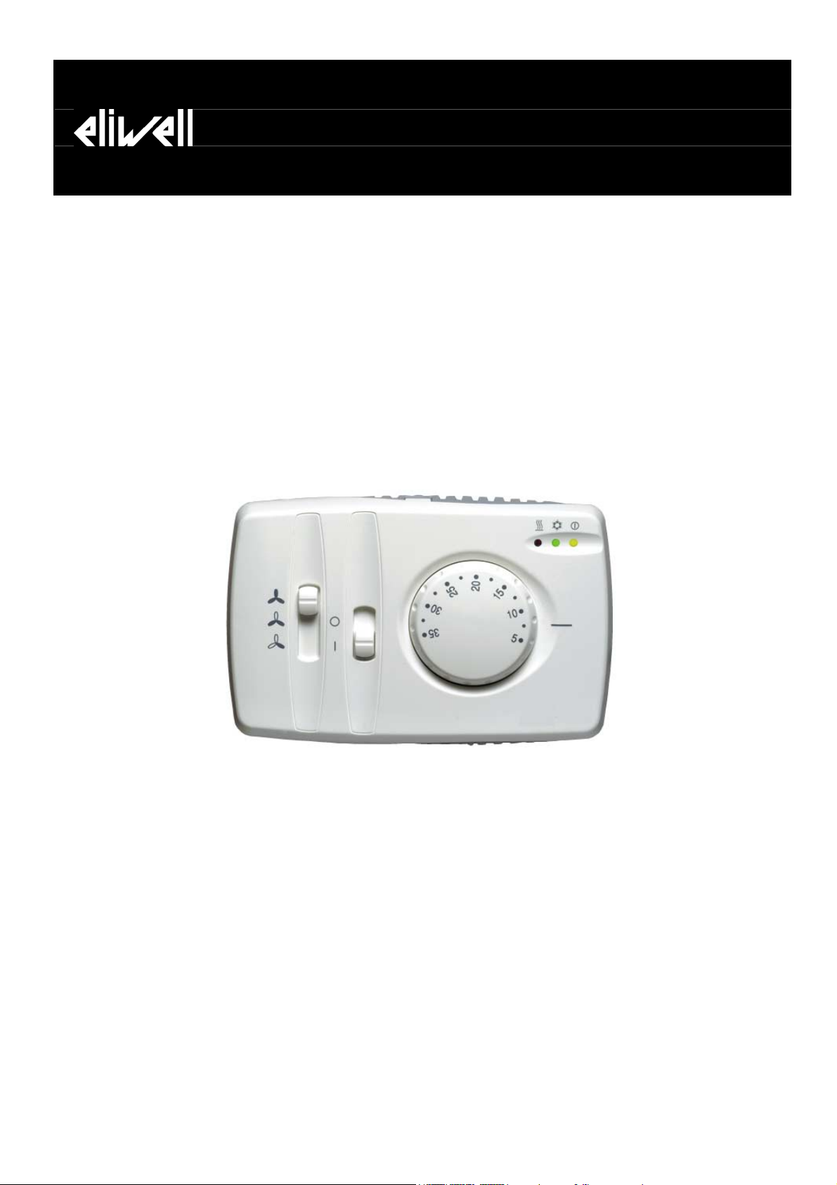
FC BASIC
Electronic Fan-Coil Controller
<IMG INFO>
340,05
Page 2

CONTENTS
1 How to use this manual........................................................................................................................................ 3
2 Introduction ............................................................................................................................................................. 4
2.1 Example of a Fan-coil installation................................................................................................................................................ 4
2.2 Available models .............................................................................................................................................................................. 5
3 Installation ................................................................................................................................................................ 7
3.1 Warnings............................................................................................................................................................................................. 7
3.2 Mounting............................................................................................................................................................................................ 7
3.3 Connection diagrams ...................................................................................................................................................................... 8
OUT1...................................................................................................................................................................................................................................................... 8
OUT2...................................................................................................................................................................................................................................................... 8
3.4 Analogue inputs................................................................................................................................................................................ 8
3.5 Digital outputs .................................................................................................................................................................................. 9
3.6 Dip switch........................................................................................................................................................................................... 9
3.6.1 Dip switch – universal models ...................................................................................................................................................................................................... 10
3.6.2 Dip switch –specific models .......................................................................................................................................................................................................... 10
4 User Interface ........................................................................................................................................................ 11
4.1 Set point dial knob ........................................................................................................................................................................ 11
4.1.1 Click-stop dial knob turning ......................................................................................................................................................................................................... 11
4.1.2 Range limitation ...............................................................................................................................................................................................................................11
4.2 Fan control slider ........................................................................................................................................................................... 12
4.3 Operating mode slider.................................................................................................................................................................. 12
4.4 Economy slider (optional)............................................................................................................................................................ 12
4.5 LED’s ..................................................................................................................................................................................................12
5 Temperature control functions ........................................................................................................................ 13
5.1 Regulation algorithm..................................................................................................................................................................... 15
5.1.1 Utility control .................................................................................................................................................................................................................................... 15
5.2 Regulation algorithm in Heating/Cooling mode....................................................................................................................16
5.2.1 REGULATION ALGORITHM IN COOL MODE ............................................................................................................................................................................ 16
5.2.2 REGULATION ALGORITHM IN HEAT MODE .............................................................................................................................................................................17
5.2.3 REGULATION ALGORITHM IN HEAT MODE WITH SUPPLEMENTARY ELECTRIC HEATERS as integrated source.................................................. 18
5.2.4 REGULATION ALGORITHM IN HEATING MODE WITH SUPPLEMENTARY AUTOMATICALLY ADJUSTING ELECTRIC HEATERS......................... 18
6 Functions................................................................................................................................................................. 20
6.1 Fan demand operation ................................................................................................................................................................. 20
6.2 Hot Start ........................................................................................................................................................................................... 20
6.3 Periodic ventilation........................................................................................................................................................................ 20
6.4 Anti-frost .......................................................................................................................................................................................... 20
6.5 Post-Ventilation.............................................................................................................................................................................. 21
6.6 Anti valve sticking .......................................................................................................................................................................... 21
6.7 Economy........................................................................................................................................................................................... 21
6.8 Window contact .............................................................................................................................................................................21
6.9 Remote Heating/Cooling.............................................................................................................................................................. 21
7 Technical features ................................................................................................................................................22
7.1 Technical data................................................................................................................................................................................. 22
7.2 Dimensions ......................................................................................................................................................................................22
7.3 Conformity declaration ................................................................................................................................................................22
8 Use of the device.................................................................................................................................................. 23
8.1 Permitted use.................................................................................................................................................................................. 23
9 Responsibility and residual risks....................................................................................................................... 23
10 DISCLAIMER ........................................................................................................................................................... 23
11 Analitic Index......................................................................................................................................................... 24
FC BASIC User Manual
2/24
Page 3
Call-outs
Cross references
Highlighted icons:
<IMG INFO>
<IMG INFO>
56,65
24,25
1
<IMG INFO>
56,65
1 HOW TO USE THIS MANUAL
In order to refer to the manual quickly and easily, customers may find the following useful:
Callout column:
Callouts on the topics described are placed to the left of the text to allow the user to find the required information
quickly.
Cross references:
All the words in italics are listed in the index with a reference to the page where they are described in more detail;
the text below serves as an example:
”activation of the alarm stops the compressors”
The italics indicate that under Compressors in the index there is a reference to the page where compressors are described
in more detail.
If the online Help on the PC is used, the words in italics become proper hyperlinks (automatic links activated by a click of
the mouse ) that connect the different sections in the manual and allow you to navigate through the document.
Some parts of the text are highlighted in the callout column using icons with the following meanings:
Note: draws attention to a specific topic that users should take into account.
Tip: highlights a suggestion that helps users to understand and use the information on the topic described.
Attention! : highlights
1. information that may damage the system or place persons, equipment, data, etc at risk
if
not known. These sections must always be read prior to use.
2. a specific topic that users should take into account so that the system does not
malfunction or is used improperly.
FC BASIC User Manual
3/24
Page 4
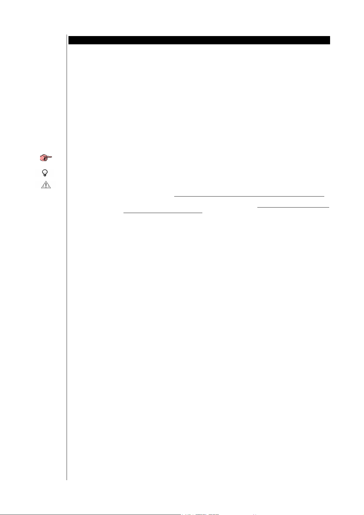
Interface F1
Interface F2
2 INTRODUCTION
FC BASIC is an electronic controller for 2-4 pipe fan-coils. It controls the fan and the valves that regulate water flow and
can also control a battery of electric heaters for winter operation.
A compact wall-mounted version is available which is easy to install and to wire.
FC Basic
Interface F1
Interface F2
2 pipe installation
A knob on the panel is used to adjust the set point, and two slider switches are used to set
a) the mode
• for Interface F1 (heating/off/cooling)
• for Interface F2 (on/off)
b) the fan speed (low/medium/high).
Some models also feature a remote Heating/cooling control and an economy function.
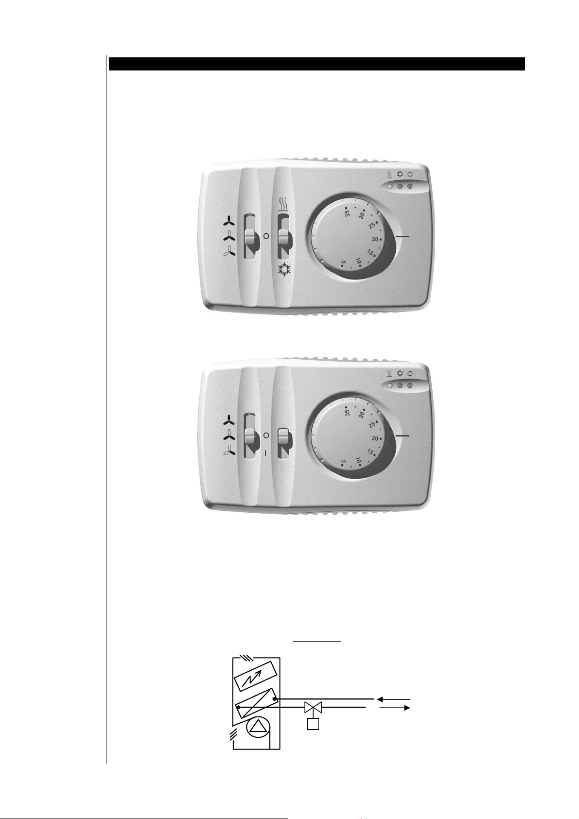
2.1 Example of a Fan-coil installation
Typical 2 and 4 pipe fan-coil installations are illustrated below:
Additional
electric heater
Water battery
2 pipe fan-coil
Motorised valve
Hot and cold water supply
Hot and cold water return
FC BASIC User Manual
4/24
Page 5
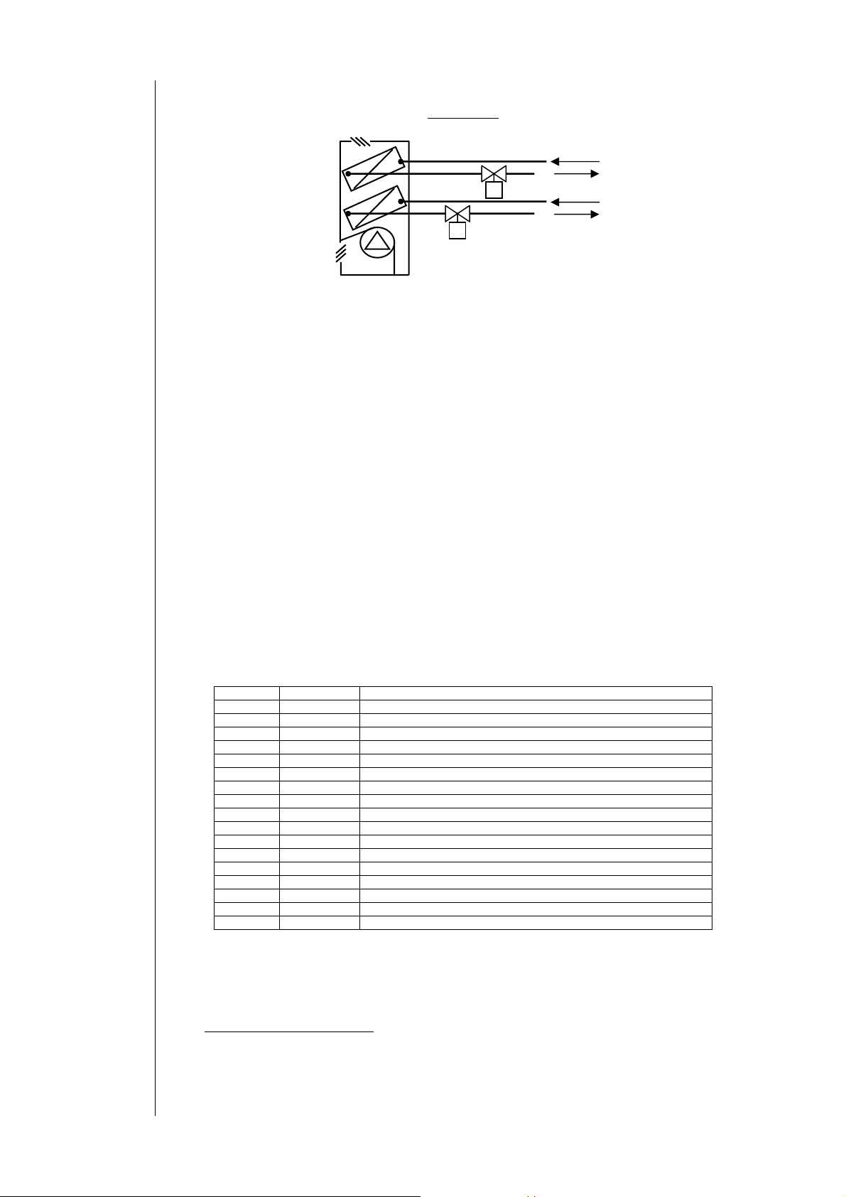
4 pipe installation
4 pipe fan-coil
Fan control
Finned battery
Valve
Electric heaters
Water battery
Hot water supply
Hot water return
Water battery
Cold water supply
Cold water return
Motorised valve
DELIVERY FAN:
The fan is located just before the finned battery; and it takes back the room air via the inlet air duct.
The air flows across the batteries before being released into the room.
If the control is installed on the fan coil unit itself, an additional return air sensor, positioned in the flow of inlet air detects
the room temperature. In this case, the temperature measurement is valid only if the flow of inlet air is sufficient to nullify
or reduce stratification phenomena in the room.
WATER BATTERY – MOTORISED VALVE
Consists of a water-air exchanger, located internally, across which the inlet air travels.
Hot or cold water, produced by a boiler or a chiller, flows through the exchanger.
There may be a dual battery supply circuit (4-pipes); the 4-pipe configuration may be set up with two motorised valves and
two independent exchangers, or with a single exchanger (2-pipes). In some cases it is important to be able to measure the
temperature of the water supplied to the battery, which may be done with a water sensor located downstream of the
battery’s return and the valve.
(see Anti valve sticking)
ELECTRIC HEATERS
The electric battery may be used to heat air in 2-pipe systems when there is only cold water available (electric heaters in
regulation), or to assist heating using water when room temperature is far from setpoint (2
nd
step electric heaters in
integration).
2.2 Available models
14 versions of FC Basic are available with different operating features, summed up in the table below:
Table of models
Product code explanation:
Example:
210/L : 2-pipe fan coil + H/Off/C mode slider (Interface F1) + electric heater present + local mode selection
U22E/R : Universal (2- or 4-pipe fan coil) + On/Off mode slider (Interface F2) + electric heater presence selectable +
Economy switch + remote H/C mode selection
U22N/R : Universal (2- or 4-pipe fan coil) + On/Off mode slider (Interface F2) + electric heater presence selectable +
Economy Function (available on terminals*)
*see electrical diagram, terminals 21-22
Position Character Description
1st 2 2-pipe fan coil system only
4 4-pipe fan coil system only
U Universal model, selectable 2- or 4-pipe fan coil system (Dip switch)
2nd 1 Mode slider switch Heating/Off/Cooling (Interface F1)
2 Mode slider switch On/Off (Interface F2)
3rd 0 Electric heater not present
1 Electric heater present
2 Electric heater presence selectable (Dip switch)
3 INTEGRATED AND AUTOMATICALLY ADJUSTING electric heater
4th E Economy switch present on top of controller
N Ecnomy Function, available omn terminals
5th /L Local Heating/Cooling mode selection (local slider switch)
/R Remote Heating/Cooling mode selection (external switch)
/W Water sensor use requested
+ remote H/C mode selection
FC BASIC User Manual
5/24
Page 6
Remote air sensor and water sensor
Remote air sensor and water sensor:
Temperature sensor NTC, plastic cap 7x25, reinforced insulation PVC cable length=1,5m
Temperature sensor NTC, metal cap 6x40, reinforced insulationPVC cable length=1,5m
Product models selection guide:
2 pipe fan coil model ● ● ● ● ● ● ● ● ● ● ●
4 pipe fan coil model ● ● ● ● ● ● ●
Universal use model ● ● ● ●
Mode Slider Interface F1 ● ● ● ●
Interface F2 ● ● ● ● ● ● ● ● ● ●
Water sensor ● ● ● ● ● ● ● ● ● ●
Remote H/C ● ● ● ●
Manual change-over ● ● ● ● ● ● ● ●
Automatic change-over ● ● ● ● ● ●
Outputs (water valve) H or C ● ● ● ● ● ● x x x ● ●
H and C ● ● ● x x x
Electrical Resistors Electric H ● ● ● x x x ● ●
Thermo-regulator H/C ● ● ● ● Y ● ● ● ● Y ●
Dead Zone Y ● Y ● ●
Hot Start driver Timer ● ● ● ● ● ● ● ● ● ● ●
Temperature ● ● ● ● ● ● ● ●
Window contact input Frost mode ● ● ● ● ● ● ● ●
= E for models with additional ECONOMY switch on top of controller
= E for models with additional ECONOMY Function, available on terminals: clean contact or under voltage
(see electrical diagram, terminals 21-22)
x : designation of output use depends on Dip switch 1, 2 and 3 position
Y : designation of function use depends on Dip switch 3 position
PLEASE NOTE:
Water Probe mandatory for FC Basic 2 pipes model with
electrical heaters not present
electrical heaters present in integration mode
Models
210*/L
211*/L
220*/W
220*/R
221*/W
221*/R
410*/L
420*/W
420*/R
U12*/L
U22*/W
U22*/R
223*/W
U23*/W
FC BASIC User Manual
6/24
Page 7
3 INSTALLATION
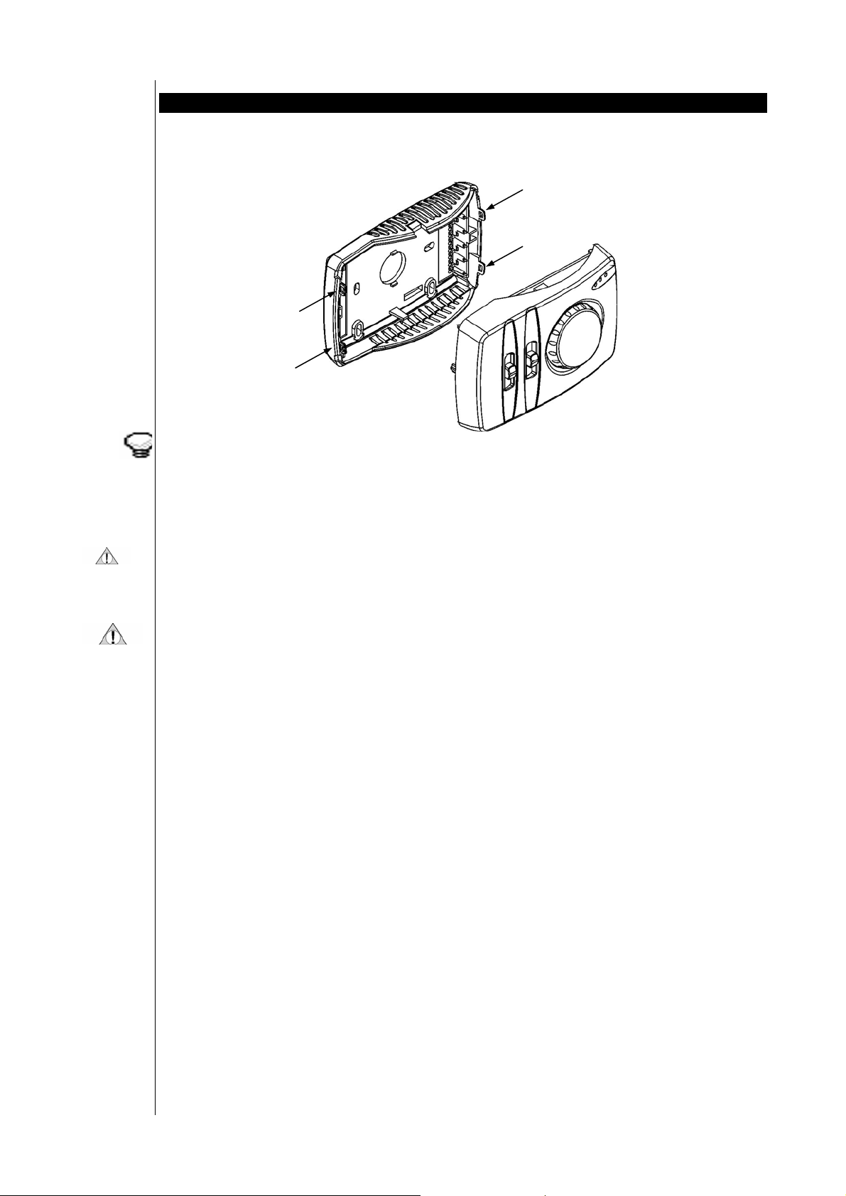
The wall-mounted version of FC Basic consists of two parts:
• the first part (connector base plate) contains connectors only, and is anchored to the wall;
• the second part (main interface) contains all electronics and controls, and can easily be fitted onto the first part.
This set-up permits easy installation with no danger of damage to electronic components.
To separate the connector base plate from the main interface, use a tiny screwdriver, insert the screwdriver into the
appropriate holes (at the side of the housing), wrest gently till both parts are separated.
FC Basic can also be installed inside the fan-coil unit. An additional remote air sensor needs to be mounted in the return
air flow on the unit.
3.1 Warnings
INSTALLATION MUST BE CARRIED OUT BY QUALIFIED PERSONNEL ONLY!
Due to the numerous functions and versions of controllers available, models offer different functions and options.
The description of the controllers in this document is general and is provided for information only.
For detailed information on the functions available, please contact an authorized dealer or the Sales Office of Eliwell.
Before installation, always read the labels fitted on the device.
Parts which are under hazardous voltage must not be accessible under regular operating conditions.
The device must be adequately protected from water and dust.
Do not install the control in environments with the following characteristics:
• Relative humidity (non-condensing) over 90%,
• Strong vibrations or shocks
• Ongoing exposure to jets of water under pressure
• Exposure to aggressive, polluting atmospheric agents which could cause corrosion or oxidation (such as sulphuric or
ammoniac substances, salt mists, fumes)
• Presence of considerable magnetic or radio interference (such as transmission antennas)
• Exposure to direct sunlight or atmospheric agents.
When connecting up controls with one another, with accessories, electric loads or other devices, take great care in relation
to the following:
• Incorrect connection with the power supply voltage could damage the control.
• Use of wire terminals which are appropriate for the terminals. Slacken the terminal screw, insert the wire terminal,
and then tighten the screw again. Check that it is tight by pulling gently on the wire. Do not use an automatic
screwing machine (or use with a torque setting of less than 50 N*cm)
• Possible electromagnetic interference: wire up low voltage utilities separately from high voltage utilities. Keep
temperature sensor cables and digital inputs separate from cables with inductive loads or power cables as much as
possible.
• Never wire power cables and temperature sensor cables through the same trunking/conduit. The remote sensor wires
must be kept far away from power devices (such as power relays). Make sure the route travelled by these cables is as
short as possible.
• Never apply loads to outputs, greater than those specified herein.
• Observe connection diagrams carefully when connecting up loads.
3.2 Mounting
The controller should be mounted in a room at a location which:
! Ensures easy access for operation
! Is free of curtains, cupboards, shelves, etc…
! Ensure free circulation of air
! Is free of direct sunlight
! Is free of draft (e.g. open window or door)
FC BASIC User Manual
7/24
Page 8
Connections
A
! Is not directly affected by a heating or cooling source
! Is not mounted on an outer wall
! Is mounted on the wall at approx. 1,5 m from the floor Mounting
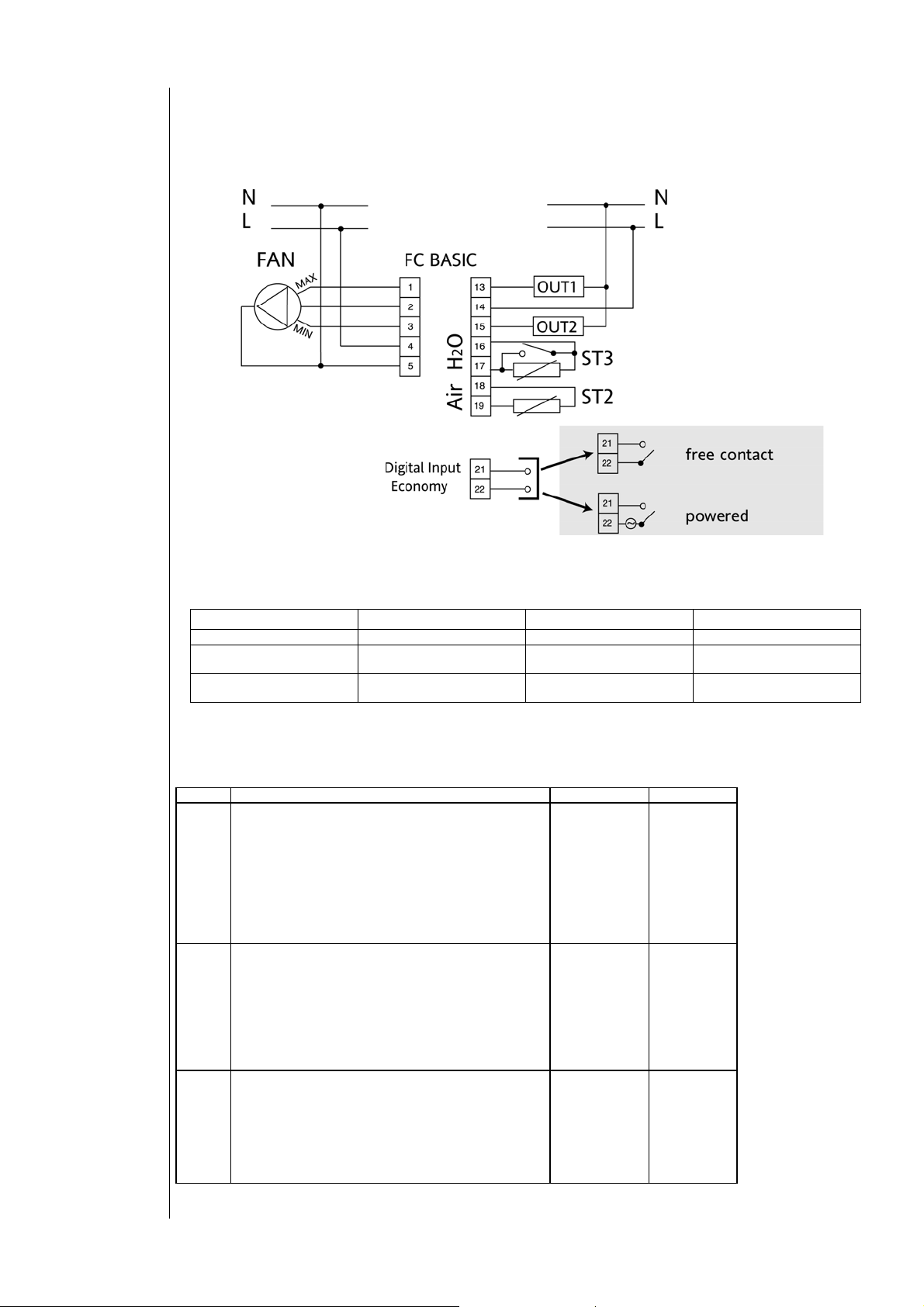
3.3 Connection diagrams
Utilities must be connected up to the FC Basic as shown below:
PLEASE NOTE: terminals 21-22 available on /N models.
Clean contact input or under voltage, depending on model (see label).
OUTPUT
2-pipe only 2-pipe with electric heater 4-pipe
OUT1
OUT2
PPLICATION
Not used Electric heater Cooling valve
Heating/Cooling valve Heating/Cooling valve
Heating valve
3.4 Analogue inputs
There are three analogue inputs available:
index Description sensor range meas. range
ST1 NTC sensor input. room temperature (built-in, always
available)
This is the temperature control sensor. It is always
integrated on the PCB.
The selection to use the local or remote sensor is done
through dip switch:
• DIP 6 = universal models
• DIP 4 = specific models
-->see dip switch table
ST2 NTC sensor input. air temperature:
This is the temperature control sensor. It is always
integrated on the PCB, but can be an additional remote
sensor, positioned in the return air flow.
The selection to use the local or remote sensor is done
through dip switch:
• DIP 6 = universal models
• DIP 4 = specific models
-->see dip switch table
ST3 NTC sensor input water temperature:
This is the sensor used to detect water temperature and
it should always be mounted downstream of the valve.
It is involved in consent and operating functions.
This input is also used for models with Remote
Heating/Cooling switch and on all other models for the
Window contact input (connection diagrams)
PLEASE NOTE: ST2 & ST3 are NOT included in the product package.
-50C° 110C° -10C° 70C°
-50C° 110C° -10C° 70C°
-50C° 110C° -10C° 70C°
FC BASIC User Manual
8/24
Page 9

Relays
Index Description use
(dial
knob)
Related topics: Set point dial knob and Range limitation
Note:
This means that functions like temperature driven Hot start, centralised On/Off (only 2-pipe models), periodic valve
opening (only 2-pipe models) will be activated or not, depending on the presence of the water sensor.
Potentiometer input:
Used to set the controller’s operating set point, between
a minimum of 5 C° up to a maximum of 35 C°.
The presence of the water sensor is automatically detected by the controller during power start-up.
-105° +105°
from average
point
Water sensor mounted upstream
The water sensor (analogue inputs) should always be mounted on the water pipe, upstream of the valve and as close as
possible to the battery. On a 4-pipe system, it must always be mounted on the hot water circuit, never on the cold water
circuit.
3.5 Digital outputs
Digital outputs consist of 3 relays
Index Function Description
FAN Delivery fan control
(refer to Fan demand operation)
OUT1 Valve or electric heater control
OUT2 Valve control Permits water to flow into the battery.
Starts ventilation. The fan control slider can be
used to set the phase on three different terminals
to permit manual selection of the 3 fan speeds.
If there is a battery of electric heaters, this relay
pilots it; if not, it is used as a second valve for a 4
pipe installation.
3.6 Dip switch
The back of the electronic board (see photo) has 4 (or 6 in case of the universal models) dip switches, the functions of
which are listed below:
FC BASIC User Manual
9/24
Page 10

<IMG INFO>
141,7
113,6
0
2
0
0
-1
127,3
106,7
3.6.1
Dip switch – universal models
* In models with INTEGRATED, AUTOMATICALLY ADJUSTING electric heaters, the HOT function is not available.
**The Dip-Switch default setting (factory pre-set) is the following:
DIP nr. Description On Off default (factory pre-set)**
6 Air sensor used Local Remote On
5 Fan status in cooling Thermostatic
Always ON Off
demand
4 Dead Zone value
Hysteresis value
3
Electric heater control Regulation Integrated Off
time for Hot Start HS=0
5°K
2°K
2°K
Off
1°K
delayed
(not delayed)*
2 2- or 4-pipe system 4-pipe 2-pipe Off
1 Electric Heater presence Present Not
Off
present
Dip switch –specific models
3.6.2
In models with INTEGRATED, AUTOMATICALLY ADJUSTING electric heaters, the HOT function is not available**
The Dip-Switch default setting (factory pre-set) is the following:
To access the DIP switches, please proceed as follows:
First separate the connector base plate from the main interface, by using a tiny screwdriver. Insert the screwdriver into the
appropriate holes (at the side of the housing), wrest gently till both parts are separated.
Turn the back of the main interface towards you and you will see the DIP switches mounted onto the PCB.
DIP nr. Description On Off default (factory pre-set)**
4 Air sensor used Local Remote On
3 Fan status in
cooling
2 Dead Zone value
Hysteresis value
1
Electric heater
control
time for Hot
Start
Thermostatic
Always ON Off
demand
5°K
2°K
2°K
1°K
Off
Regulation Integrated Off
HS=0
delayed
(not delayed)*
FC BASIC User Manual
10/24
Page 11

and 35°C:
and 25°C:
4 USER INTERFACE
FC Basic has three main controls plus one optional control:
• Dial knob
• 2 sliders
• 1 economy slider (optional)
4.1 Set point dial knob
Potentiometer for setting operating set point.
Operating set point is altered on the basis of the angle set, from 5 to 35 Celsius.
Excursion from the potentiometer centre point is an angle of +/- 105°.
Click-stop dial knob turning
4.1.1
A sensible click-stop mechanism of approx. 0,5° per position gives the user a more accurate feeling during adjustment.
4.1.2
Range limitation
The set point may be limited on all models by positioning 2 pegs, (plugs) which are mounted under the dial knob, at a
specific minimum and maximum value. When the 2 pegs are mounted one next to the other, it is even possible to lock the
set point at a specific value.
Please proceed as follows:
1. Separate the connector base plate from the main interface, by using a tiny screwdriver. Insert the screwdriver into the
appropriate holes (at the side of the housing), wrest gently till both parts are separated.
2. Before proceeding with the next step, first turn the dial knob to the mid-position when you want to limit (min. /
max.) the range. When you want to lock the set point, first turn the dial knob in the desired lock position value.Turn
the back of the main interface towards you and you will see a hole somewhere in the middle of the electronic board.
Push gently on the pin connected with the dial knob till it becomes released from the main interface
3. You can now remove the dial knob on the front of the main interface and the range limitation becomes accessible.
After you entered the pegs in the desired limitation position, mount the dial knob back onto the interface in the
correct way.
11
Factory setting of the limitation pegs at 5°C
Economy slider (optional)
22
11
33
Example of a range limitation between 15°C
LED’s
Range limitation
Operating mode slider
Fan control slider
FC BASIC User Manual
11/24
Page 12

4.2 Fan control slider
Switches the phase sectioned by the fan relay on three motor windings to achieve three different fan speeds:
High/Medium/Low.
Low speed: Medium speed: High speed:
4.3 Operating mode slider
Depending on the model (refer to table of models), it is possible to select Heating/off/Cooling operating mode or on/off
(0 / I) operating mode.
Heating mode: Cooling mode: Off mode: On mode:
O I
4.4 Economy slider (optional)
Located at the top of the controller and used to operate the economy function.
4.5 LED’s
Three LED’s are used to indicate the actual mode:
On/economy LED: (YELLOW)
Stays on during normal operation; Blinks during economy operation
Cooling LED: (GREEN)
Illuminates during cooling demand (cool) and in the Dead zone.
Blinking: indicates that regulation algorithm has not been satisfied but consent, by the water sensor, is not being given to
start the fan.
Stays on: cooling is available(fan and valve active).
Heating LED: (RED)
Illuminates during heating demand (heat) and in the Dead zone.
Blinking: indicates that regulation algorithm has not been satisfied but consent, by the water sensor (2-pipe models only),
is not being given to start the fan. (refer to Hot Start)
Stays on: heating is available (fan, valve and/or electric heater are active)
All LED’s Blink for 3 seconds when the controller is turned onto the power supply.
Alarm indication
All LED’s continuously Blink to indicate an alarm status. An alarm will be generated if one of the sensors is damaged,
disconnected (some models mandatory need the water sensor), or short circuited, until the problem has been solved. This
will also appear when the window contact has been activated (contact closed).
FC BASIC User Manual
12/24
Page 13

Operating modes
Cool
Heat
Auto
Operating modes table
Manual change
over
Automatic change
over
5 TEMPERATURE CONTROL FUNCTIONS
Depending on the model and available selections, FC Basic may be operated in the following modes:
• COOL (summer operation)
• HEAT (winter operation)
• AUTO (automatic summer – winter selection)
Cooling: this is “summer” operating mode; the machine is configured for cooling.
Heating: this is “winter” operating mode; the machine is configured for heating.
Auto: The machine is configured to switch automatically from cool to heat mode and vice versa. Depending on the
temperature detected by the water sensor (2-pipe system) or air sensor (4-pipe system or 2-pipe with INTEGRATED AND
AUTOMATICALLY ADJUSTING electric heaters).
The utilities controlled in the various operating modes are shown in the table below:
Mode
HEAT
COOL
AUTO AUTOMATIC Dynamic operation in the following modes:
Summer – Winter (Cool – Heat) operating mode may be set manually in models with a heating – cooling slider , locally
(operating mode slider) or remote(Remote Heating/Cooling).
The following regulation algorithms are available, depending on the model:
• Winter/summer (Heat / Cool)
• Dead zone with lateral band
In 2-pipe systems models with water sensor, operating mode is selected automatically in function of the temperature
detected by the water sensor:
• Cool (Summer) operation for temperatures of less than 15 C°
• Heat (Winter) operation for temperatures of more than 30 C°
Setting Utilities controlled
MANUAL
• Valve: water (for 2-pipe fan-coil), hot water (for 4-pipe fan-coil)
• Fan (3 manually set speeds)
• Electric heater (enabled by dip switch dip 1 – universal models only)
MANUAL • Valve: water (2 pipes), cold water (4 pipes)
• Fan (3 manually set speeds)
• HEAT
• COOL
• “STAND BY” condition (Summer- Winter), on the basis of comparison of water
temperature with set point setting
• «OFF» (dead zone), depending on the difference between air temperature and set
point temperature.
SUMMERTIME
cool./raff.
ESTIVO
stand-by
30
15
WINTERTIME
INVERNALE
<IMG INFO>
226,6
220,35
0
2
99,25
9
-1
212,25
213
The automatic water temperature based change-over (SUMMER / WINTER) takes place as illustrated in the drawings below
and generates consent to the activation of available resources.
heat./risc.
FC BASIC User Manual
13/24
Page 14

• In COOL mode (consent
is explained below (with relative changes to consent):
COOL
to valve and fans at water temperatures lower than 15°C), the switch to HEAT
15 C
30 C
water
temperature C
MODE
HEAT
VALVE ON
VALVE MODE
VALVE OFF
FAN ON
FAN MODE
FAN OFF
<IMG INFO>
• in HEAT mode (consent to valve and fans at water temperatures above 30°C), the switch to COOL is
explained below (with relative changes to consents):
15 C
30 C
water
temperature C
HEAT
MODE
COOL
VALVE MODE
VALVE ON
VALVE OFF
FAN MODE
FAN ON
FAN OFF
<IMG INFO>
FC BASIC User Manual
14/24
Page 15

Automatic DEAD
O
h
C
c
ZONE change-over
When the function mode is selected automatically depending on the difference between ambient temperature and the set
point temperature, this is referrred to as an automatic DEAD ZONE change-over with lateral band.
Switching between heat and cool settings takes place automatically as illustrated below.
set-point
band/banda
eat./risc.
FF
ool./raff.
hysteresis/isteresi
hysteresis/isteresi
room temp.
temp.ambiente ˚
5.1 Regulation algorithm
FC Basic controls utilities on the basis of consents (determined as explained above) and the status of the temperature
controller. The latter is a set point function that can be set using the scaled knob.
In a two-pipe installation the regulation algorithm is configured:
• For the Dead zone if there are electric heaters in regulation (or INTEGRATED AND AUTOMATICALLY ADJUSTING) and
there is no local / remote heating/cooling selection.
• For Summer/Winter if there is a water sensor or local / remote heating/cooling selection (refer to operating mode
slider and Remote Heating/Cooling)
In a four-pipe installation the regulation algorithm is configured:
• For Summer/Winter, if there is a local / remote heating/cooling selection (refer to operating mode slider and Remote
Heating/Cooling).
• For the Dead zone, in all other cases.
The hysteresis and the Dead zone band, are determined by
• dip switch 4 – universal models
• dip switch 2 – specific models.
5.1.1
Utility control
• Operating modes (heat / cool) are affected by the consent to the water sensor, if present, for 2-pipe system models.
If both water heating and supplementary electric heaters, set as integrated source, are both available, the electric
heaters will be added as a second step separated from the first step by a distance equal to the neutral band
(operation of INTEGRATED AND AUTOMATICALLY ADJUSTING electric heaters is more complex. See the relative
section).
•
• If there are electric heaters set as regulation, heat is regulated only with electric heaters and corresponds to the
“heat” step in the diagrams.
• Dip switch:
• dip switch 5 – universal models
• dip switch 3 – specific models.
may be used to select whether the fan is On or Off once the required temperature has been achieved in cooling
mode; in heating mode it will always be off.
If there is a water sensor, and it does not give consent for cooling operation and the regulation algorithm is set to cooling
operation, the fan the fan is switched off respecting the time of 1 minute for post-ventilation in the specified cases (see
related paragraph).
Configurations with no heating/cooling slider (operating mode slider) must have four pipes or electric heaters set as
regulation or a water sensor.
FC BASIC User Manual
15/24
Page 16

Observe the explanatory diagrams below:
5.2 Regulation algorithm in Heating/Cooling mode
Regulation
algorithm in
cooling mode
cool./raff.
OFF
5.2.1 REGULATION ALGORITHM IN COOL MODE
set-point
room temp.
temp.ambiente ˚C
hysteresis/isteresi
FC BASIC User Manual
16/24
Page 17

Regulation
algorithm in
heating mode
set-point
heat./risc.
OFF
REGULATION ALGORITHM IN HEAT MODE
5.2.2
room temp.
temp.ambiente ˚C
hysteresis/isteresi
FC BASIC User Manual
17/24
Page 18

Regulation
r
i
˚C
i
e
algorithm with
supplementary
electric heaters
REGULATION ALGORITHM IN HEAT MODE WITH SUPPLEMENTARY ELECTRIC HEATERS as integrated
5.2.3
source
set-point
ntegrated
lectric heaters
esistenze elettriche
n integrazione
band/banda
valvola/valve
OFF
<IMG INFO>
339,7
150,35
hysteresis/isteresi
hysteresis/isteresi
room temp.
temp.ambiente
REGULATION ALGORITHM IN HEATING MODE WITH SUPPLEMENTARY AUTOMATICALLY ADJUSTING
5.2.4
ELECTRIC HEATERS
In models with INTEGRATED AND AUTOMATICALLY ADJUSTING electric heaters, heating components are determined by
the temperature read by the water probe as well as always being subject to the consents programmed for this sensor.
With this configuration, the automatic change-over always takes place at the air probe temperature (Dead Zone). Setting
depends on water temperature, as shown in the following three examples:
N.B.: There is a fixed hysteresis of1°C between temperatures of 15°C and 30°C to prevent constant flucturations
between A and B and between B and C.
For example, for rising temperatures, the switch from A to B takes place at 15.5°C whilst for falling temperatures,
the switch from B to A takes place at 14.5°C. The same happens at the 30°C threshold (real thresholds of 29.5
and 30.5°C).
FC BASIC User Manual
18/24
Page 19

EXAMPLE A
r
i
˚C
i
e
The water temperature is too low to guarantee any transfer of heat from the water: the electric heaters alone are used (as
if in regulation mode):
EXAMPLE B
Intermediate situation, valve and electric heaters are activated together with the temperature controller in heating mode
(winter).
EXAMPLE C
The temperature of the water is sufficient to transfer heat, the electric heaters (more cost-intensive) are a second option:
temperature control is the same as the example with electric heaters in integration.
set-point
ntegrated
lectric heaters
esistenze elettriche
n integrazione
valvola/valve
hysteresis/isteresi
OFF
band/banda
room temp.
temp.ambiente
hysteresis/isteresi
FC BASIC User Manual
19/24
Page 20

6 FUNCTIONS
6.1 Fan demand operation
The fan will only be operated in the manually selected speed, if the regulator has detected a request for Heating or
Cooling. During dead zone the fan will be OFF. Through a DIP switch:
• dip switch 5 – universal models
• dip switch 3 – specific models.
you can select if the fan in cooling mode should run or not when the regulator is satisfied.
6.2 Hot Start
The Hot Start function prevents blowing a draught of cold air into the room during winter operation.
It means preheating of the exchanger (finned battery) before ventilation begins.
If a water sensor is present (not possible on remote H/C models) ventilation will only start if the water sensor detects a
temperature above 30 degrees. If this is not the case, it waits for consent from the sensor.
If there is no sensor, ventilation will always start after the 150 seconds delay time from valve opening.
PLEASE NOTE: if
• dip switch 3 = ON (universal models)
• dip switch 1 = ON (specific models)
the Hot Start delay is equal to zero (HS=0)
During the Hot start delay (through timer or water sensor), the red LED (heating) will Blink After the delay, when the fan
starts, the red LED will illuminate continuously.
This function is only enabled in heating mode.
The “temperature driven” Hot start function is only available on models with water sensor present for:
• 2-pipe installations with electric heaters set as integrated source (2° heating step)
• 4-pipe installations
The water sensor (analogue inputs) should always be mounted on the water pipe, upstream of the valve and as close as
possible to the battery. On a 4-pipe system, it must always be mounted on the hot water circuit, never on the cold water
circuit.
Water sensor mounted upstream
6.3 Periodic ventilation
Ventilation will be started for two (2) minutes at the end of the cycle to recycle air on the room air sensor if there has
been no ventilation in the last twenty (20) minutes.
This prevents stratification of the air in the room, which will falsify the room temperature reading.
6.4 Anti-frost
A heating regulation algorithm with a set point of 8 C° always remains active, ignoring water sensor consent and operating
mode. It always comes on if the temperature drops below 8 C°, even if the controller is switched off.
This prevents equipment inside the room from freezing.
<IMG INFO>
A model with anti-frost function disabled is available on demand
FC BASIC User Manual
20/24
Page 21

6.5 Post-Ventilation
The fan continues to run for 1 minute* after a heating source (heating valve or electric heater) is turned off.
This function prevents overheating inside the fan coil unit.
*NB: Post-ventilation always
occurs (from Heat to Cool), the fan does not stop but continues to work for the determined minute.
lasts 1 minute (it has the priority on all other functions). For example, when a change of mode
6.6 Anti valve sticking
This function avoids valve sticking after they’ve remained in the closed position for a long time. Each time a valve output
has been operated, a timer will be started. When the timer reaches the pre-set value (approximately 1 week), the valve
output will be forced open for 3 minutes.
6.7 Economy
The economy mode can be selected:
• Through an optional switch, on top of the controller,
• Through the Economy Function , available on terminals, clean contact or under voltage terminal (depending on
models)
This function “shifts” the set point as described below:
• In HEAT (winter) mode: the set point is decreased by 6° C
• In COOL (summer) mode: the set point is increased by 8° C
This function will save energy, for instance, during the night or a holiday period.
This function is available on all models with product codes having suffix “E” or “N”.
The Yellow LED will Blink when the ECO mode is operational
6.8 Window contact
Through a window contact, (voltage free) connected onto analogue input ST3 (connection diagrams), the controller can be
switched in standby mode (anti-frost mode active), when the window contact is closed. The purpose of this function is to
prevent waste of energy when the window is opened by personnel.
This feature only applies to models which do not have the remote Heating/Cooling input.
The contact MUST be voltage free.
When the window contact is closed, all LED’s will blink continuously. (Alarm indication)
To connect one window contact with several FC Basic controller inputs (ST3), you need to use an additional relay contact
for each controller. A relay with a single SPST output contact or with multiple SPST contacts can be used.
6.9 Remote Heating/Cooling
There are dedicated models (with suffix “/R”, refer to Available models) which permit you to change the mode through an
external switch; connected onto input ST1.
The contact MUST be voltage free.
Contact open = Cooling mode; contact closed = Heating mode.
To connect one remote H/C switch (contact) with several FC Basic controller inputs (ST3), you need to use an additional
relay contact for each controller. A relay with a single SPST output contact or with multiple SPST contacts can be used.
FC BASIC FC BASIC
Remote
Heating/Cooling
switch
FC BASIC User Manual
21/24
Page 22

7 TECHNICAL FEATURES
7.1 Technical data
Wall mounted version
Typical Maximum Minimum
Power supply voltage 230V~ 253V~ 207V~
Power supply frequency 50/60 Hz 52/63 Hz 47/57 Hz
Maximum absorbed power 12W 12W 12W
Insulation class II II II
Protection grade IP30 IP30 IP30
Operating temperature 25C° 60C° 0C°
Operating humidity (non-condensing) 30% 90% 10%
Storage temperature 55C° 85C° -20C°
Storage humidity (non-condensing) 30% 90% 10%
• Digital outputs rating : 230V~ 5 (2)A
• Analogue inputs : 1 (+1) NTC probes;
• Assembly : wall mounted
• Housing: colour : Front : white
• Connections : screw terminals – SAURO connector for wires
7.2 Dimensions
120x80x40 mm
Base plate ; grey
! max 2.5 mm² rigid cable;
! max 1.5 mm² flexible cable.
40 80
7.3 Conformity declaration
The product complies with the following European Community Directives and standards:
73/23/EEC and subsequent amendments, in compliance with the following standards:
60730-2-9
89/336/EEC and subsequent amendments
60730-2-9
EMISSION: EN55014-1
IMMUNITY: EN55014-2
120
FC BASIC User Manual
22/24
Page 23

8 USE OF THE DEVICE
8.1 Permitted use
To ensure safety, FC Basic must be installed and operated in accordance with the instructions supplied, and access to high
voltage components must be prevented under regular operating conditions. The device shall be properly protected against
water and dust and shall be accessible by using a tool only.
Any use other than the permitted use is forbidden.
9 RESPONSIBILITY AND RESIDUAL RISKS
Eliwell shall not be held liable for any damage incurred as a result of:
installation/use other than those intended, and, in particular, failure to comply with the safety instructions specified by
applicable regulations and/or provided in this document;
use with equipment which does not provide adequate protection against electric shocks, water and dust under the
effective conditions of installation;
use with equipment which permits access to hazardous parts without the use of tools;
installation/use with equipment which does not comply with current regulations and legislation.
10 DISCLAIMER
This document is exclusive property of Eliwell Controls srl. and cannot be reproduced and circulated unless expressly
authorized by Eliwell Controls srl
Although all possible measures have been taken by Eliwell Controls srl l. to guarantee the accuracy of this document, it
does not accept any responsibility arising out of its use.
FC BASIC User Manual
23/24
Page 24

11 ANALITIC INDEX
2
2 pipe installation.............................................................4
4
4 pipe installation.............................................................5
A
Analogue inputs................................................................8
Anti valve sticking.......................................................... 21
Anti-frost.......................................................................... 20
Auto................................................................................... 13
Automatic change over................................................ 13
Automatic DEAD ZONE change-over........................ 15
Available models...............................................................5
C
Call-outs.............................................................................3
Click-stop dial knob turning........................................ 11
Conformity declaration ................................................ 22
Connection diagrams.......................................................8
Connections........................................................................8
Cool ................................................................................... 13
Cross references .................................................................3
D
Digital outputs...................................................................9
Dimensions ...................................................................... 22
Dip switch ...........................................................................9
Dip switch – universal models................................ 10
Dip switch –specific models......................................... 10
DISCLAIMER..................................................................... 23
E
Economy........................................................................... 21
Economy slider (optional)............................................ 12
Electric heaters ..................................................................5
Example of a Fan-coil installation ................................4
F
Fan control .........................................................................5
Fan control slider ........................................................... 12
Fan demand operation................................................. 20
Finned battery....................................................................5
FUNCTIONS..................................................................... 20
H
Heat................................................................................... 13
Highlighted icons: .............................................................3
Hot Start........................................................................... 20
HOW TO USE THIS MANUAL..........................................3
I
INSTALLATION...................................................................7
Interface F1.........................................................................4
Interface F2.......................................................................4
INTRODUCTION ................................................................4
L
LED’s ..................................................................................12
M
Manual change over......................................................13
Mounting............................................................................ 7
O
Operating mode slider...................................................12
Operating modes............................................................13
Operating modes table .................................................13
P
Periodic ventilation ........................................................ 20
Permitted use................................................................... 23
Post-Ventilation..............................................................21
R
Range limitation.............................................................11
Regulation algorithm .................................................... 15
REGULATION ALGORITHM IN COOL MODE ............16
Regulation algorithm in cooling mode.....................16
REGULATION ALGORITHM IN HEAT MODE .............17
REGULATION ALGORITHM IN HEAT MODE WITH
SUPPLEMENTARY ELECTRIC HEATERS as
integrated source .......................................................18
Regulation algorithm in heating mode ....................17
REGULATION ALGORITHM IN HEATING MODE WITH
SUPPLEMENTARY AUTOMATICALLY ADJUSTING
ELECTRIC HEATERS ....................................................
18
Regulation algorithm in Heating/Cooling mode.... 16
Regulation algorithm with supplementary electric
heaters ..........................................................................18
Relays ..................................................................................9
Remote Heating/Cooling..............................................21
RESPONSIBILITY AND RESIDUAL RISKS ..................... 23
S
Set point dial knob......................................................... 11
T
Technical data ................................................................22
TECHNICAL FEATURES ..................................................22
TEMPERATURE CONTROL FUNCTIONS..................... 13
U
USE OF THE DEVICE .......................................................23
USER INTERFACE.............................................................11
Utility control ..................................................................15
V
Valve.................................................................................... 5
W
Warnings........................................................................... 7
Window contact .............................................................21
Page 25

FC BASIC User Manual
2006/9/
Cod: 8MA10103
FC BASIC User Manual
25/24
 Loading...