

Page 1
Elite Technology
ET Series DVR
User Guide
Electronics Line Site (DVR)
Electronics Line Center (Remote)
Page 2

2
Page 3

Contents
Electronics Line Site
• Main Screen 5
• Entering Setup mode 9
• Hardware Setup 10
o Camera Setup 11
o Sensor Setup 13
o Control Setup 14
o External Monitor 16
• Motion Setup 17
o Setup for Individual Cameras 17
o Setup for All Cameras 21
• Schedule Setup 23
o Record Modes 23
o How to set schedule 24
o Set Holiday 26
o Simple / Advanced Mode 27
• Screen Division 28
• Modem Setup 29
o Using the “Ping” utility 32
o Configuring the modem 35
• Site Information 41
• Password Setup 46
• Audio Setup 48
o
Microphone and Speaker Setup 49
• System Setup 55
o Backup Settings 56
o Creating a Backup Schedule 58
o Adding Backup Media 60
o Remote Backup Media 61
o Easy Update 64
• Motion Tracking Setup 68
• Storage Setup 72
• E-Map Setup 74
o Camera 76
o Control 77
o Sensor 78
• Pan Tilt Zoom Control 80
3
Page 4

• Search Mode 82
o Calendar 82
o Recorded Data Timeline 84
o Still Image Tools 85
o Search Tools 86
o Playback Controls 87
o Index Search 88
o Search Option Panel 89
o Printing an Image 90
Installing a local Printer 91
Installing a Network printer 93
o Backup 94
Floppy Backup 95
Watermark Checker 95
Time Backup 96
AVI Backup 97
Select Media 98
o Formatting CD-R/CD-RW disks 100
Contents
Electronics Line Site
4
Page 5
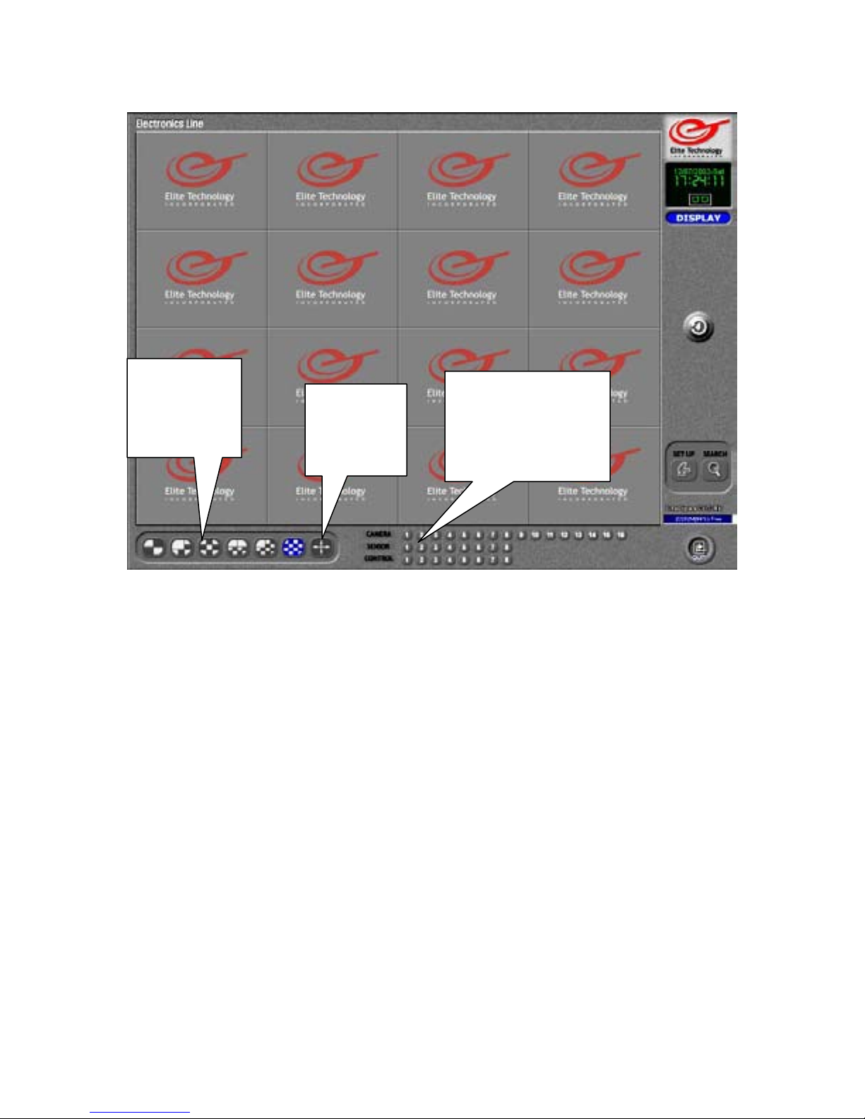
Main Screen
Screen
Division
Selections
Full
Screen
View
Screen Division Selections
Select the number of cameras you wish to view on the main screen.
Choose 4, 6, 9, 10, 13, or 16 camera splits
The cameras that will appear in each view are assignable in setup under “Screen Division”
Full Screen View
This button will set the main screen to “Camera only” view. The GUI (Graphic User
Interface) which includes the Screen Division buttons, the Event Indicators, the Clock,
Setup and Search buttons, Power button, etc. will be hidden.
Right click on the screen to return to normal view.
Camera, Sensor, and Control Relay Event Indicators
Each numbered button corresponds to the similarly numbered device in each category.
Camera indicators will flash when a camera detects motion. Sensor indicators will flash
when a device (Glass break or motion detector) is tripped.
Control indicators will flash when a relay (Alarm, siren, strobe, etc.) has been activated.
Control relays may also be manually activated by left clicking on the indicator. Click on it
again to deactivate.
Camera, Sensor,
and Control
Relay Event
Indicators
Page 6
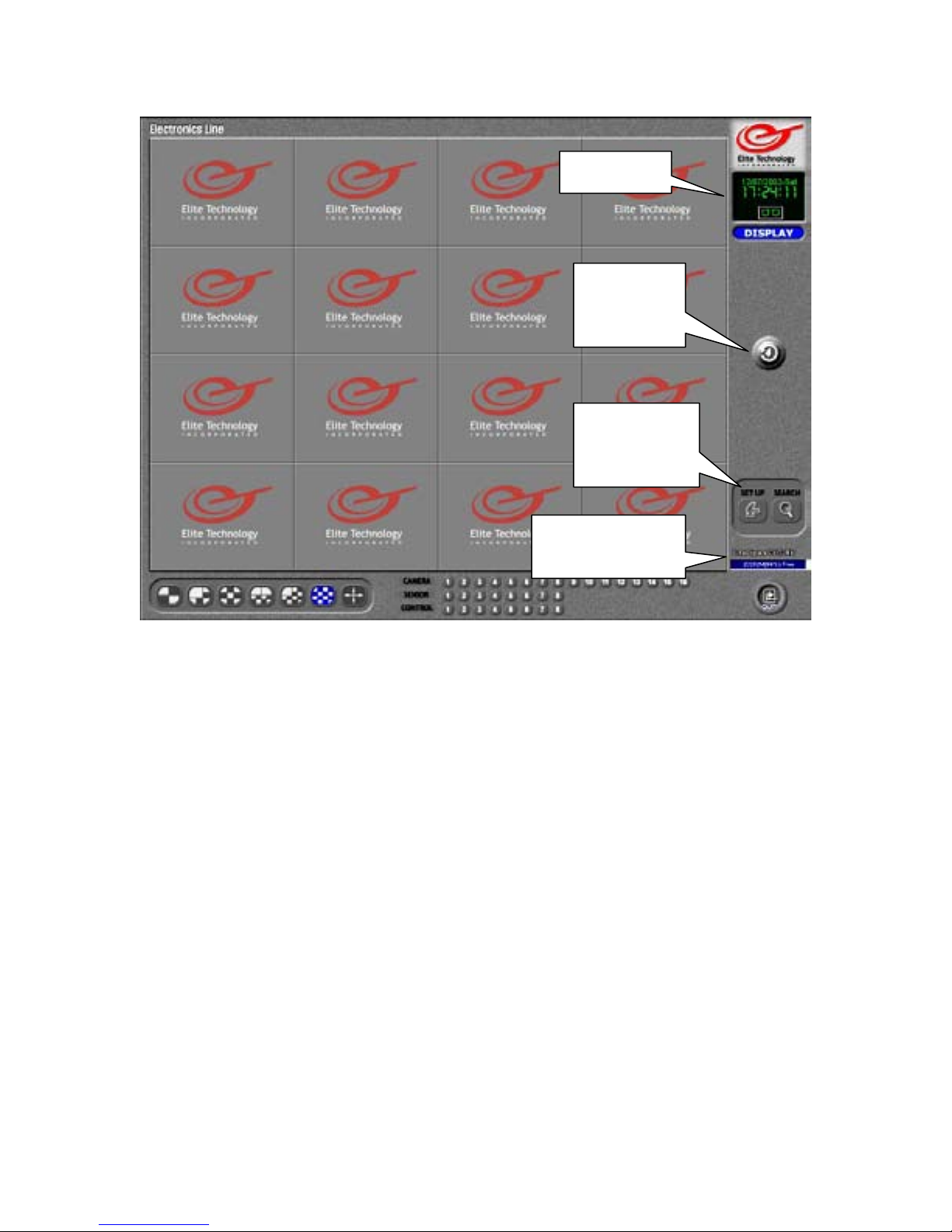
Main Screen
Clock
Indicates current date and time
Quad Rotation Mode
Sets main view to 4 camera split and rotates view continuously through all active cameras
starting with 1~4, then 5~8, then 9~12, then 13~16, then back to 1~4, etc.
Click on an image, or select a Screen division button to stop rotation and return to normal
mode.
Setup and Search Mode
Left click to enter Setup (Camera selection, Screen division, Schedule, Audio, Motion, etc.)
or Search Mode (Review and backup recorded data)
Storage Indicator
Top line shows total Hard Drive space allocated and available for data storage.
Numbers in the blue box show Hard Drive space that has been used for data storage in
Megabytes and Percentage of free space remaining. When percentage of free space reaches
0%, the DVR has used all available storage and will begin to overwrite (replace) the oldest
recorded data.
(It is normal for the ‘Free Space’ indicator to read ‘0% Free’ once the DVR has started
overwriting the oldest data. This number will not change unless you reallocate (erase) the
storage drive.)
Clock
Quad
Rotation
Mode
Setup and
Search
Mode
Storage
Indicator
6
Page 7
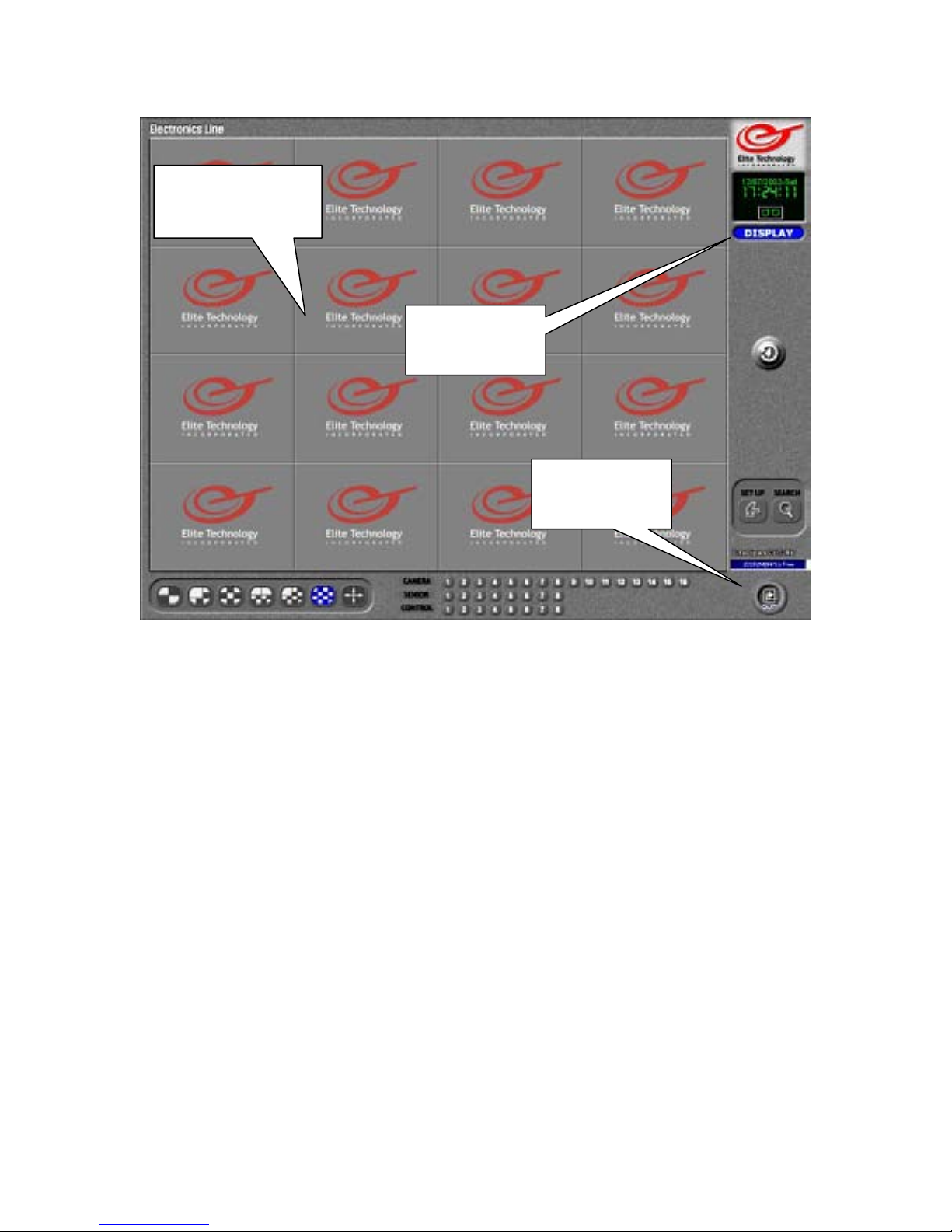
Main Screen
Main View Screen
This is where the live images from your cameras will appear.
Left click on any image to bring it to full screen view. Left click on the image again to
return to normal view.
Mode Indicator
Mode indicator will indicate whether you are in Display, Search, or Pan /Tilt mode.
Power Button
Left click on the power button in Display mode to turn off the DVR.
Unit will stop recording and turn itself off. Use the Power switch (on the front of the DVR)
to restart the unit.
Main View
Screen
Mode
Indicator
Power
Button
7
Page 8
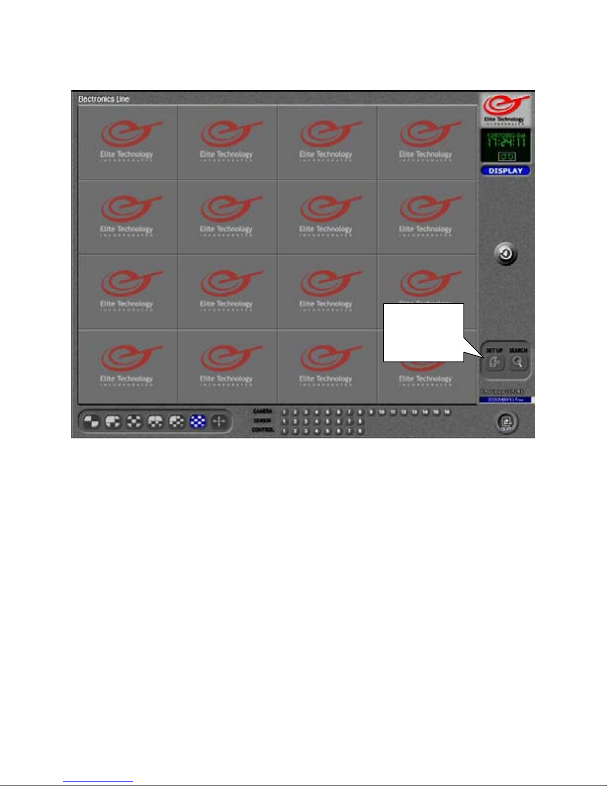
Setup
Your new Elite Technology ET-Series DVR is “Ready to Go” right out of the box.
It is factory preset to start up and begin recording data without any effort on your part.
Just hook up your cameras and turn it on.
In order to fine tune your installation and customize the DVR to get the best performance
for your particular situation, or to setup extra features such as Pan/Tilt/Zoom cameras,
Sensors and Control relays, Record mode quality and scheduling, Custom screen divisions,
etc., the Elite Technology ET-Series is equipped with an extensive array of options
available through the “Setup” mode.
Left click on the “Setup” button to enter Setup mode.
8
Left click
to enter
Setup
Page 9
Setup
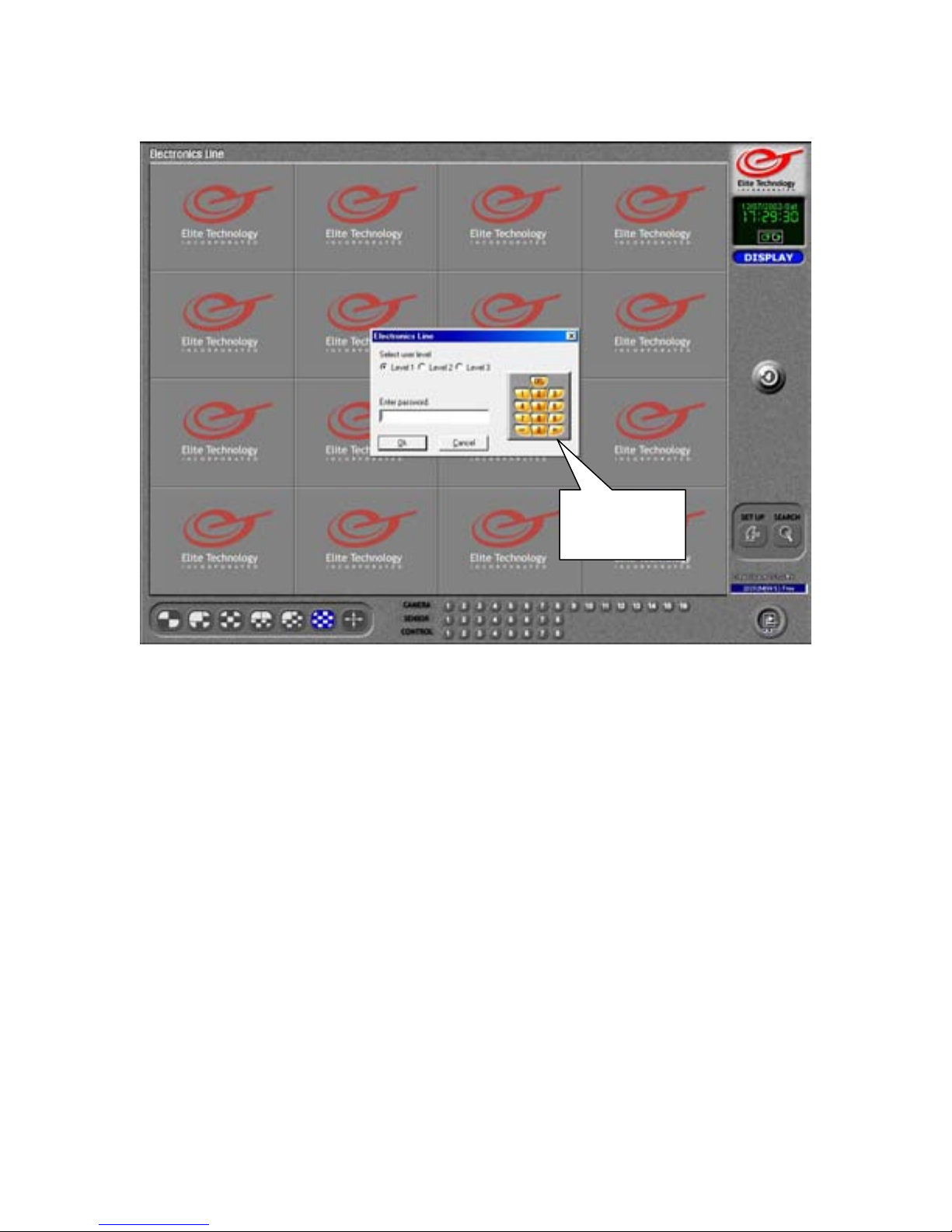
When you click on setup for the first time you will be prompted to enter a
password.
Leave the user level set to Level 1 (Administrator) and use the keyboard to enter a 4 digit
numeric password (4 characters, all numbers). You may left click on the numbers on the
‘Virtual Keypad’ if no keyboard is available.
You may also press “Enter” on your keyboard or click on “OK” with the left mouse button
if you want no password set up at this time. (You can change this later in the “Password
Setup” section.)
You will then be asked if you want to create the default user database.
Click on “Yes” or press “Enter” on your keyboard to continue.
You will then be prompted to “Confirm” or, re-enter your password again to gain entry to
Setup mode.
Virtual
Keypad
Remember your password!
Once you have created the password database you will not be able to access Setup or
Search mode without it.
9
Page 10
Hardware Setup
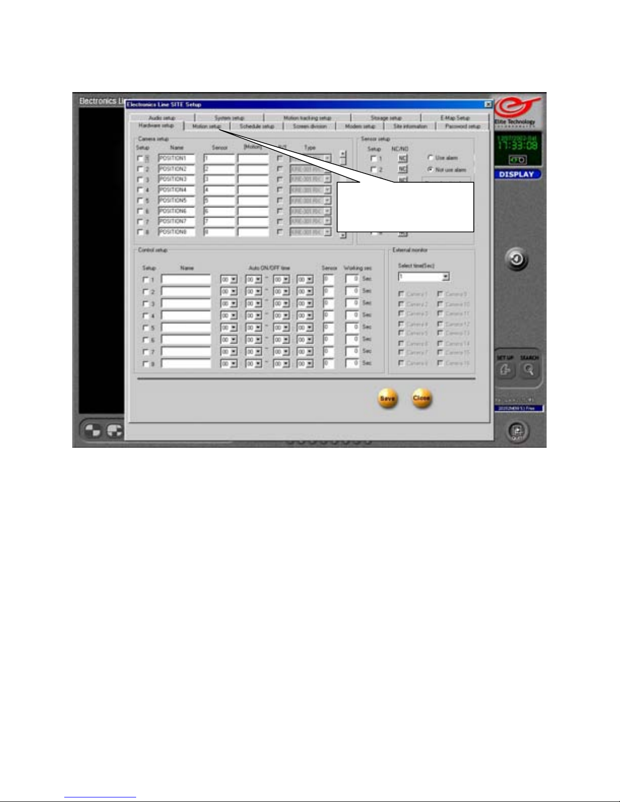
When you enter Setup mode you can access all of the functions of the DVR and customize
settings for your installation to achieve the best performance of your unit in any
environment.
Most key functions (Camera types, color settings, motion settings, frame rates, etc.) can be
set up on an individual camera by camera basis.
The Setup mode is organized on several “Pages” accessed by the tabs at the top of the
panel. Left click with the mouse on any tab to access that page. The first page that appears
is the “Hardware Setup” page.
Click on a tab to
select a Setup Page
10
Page 11
Hardware Setup
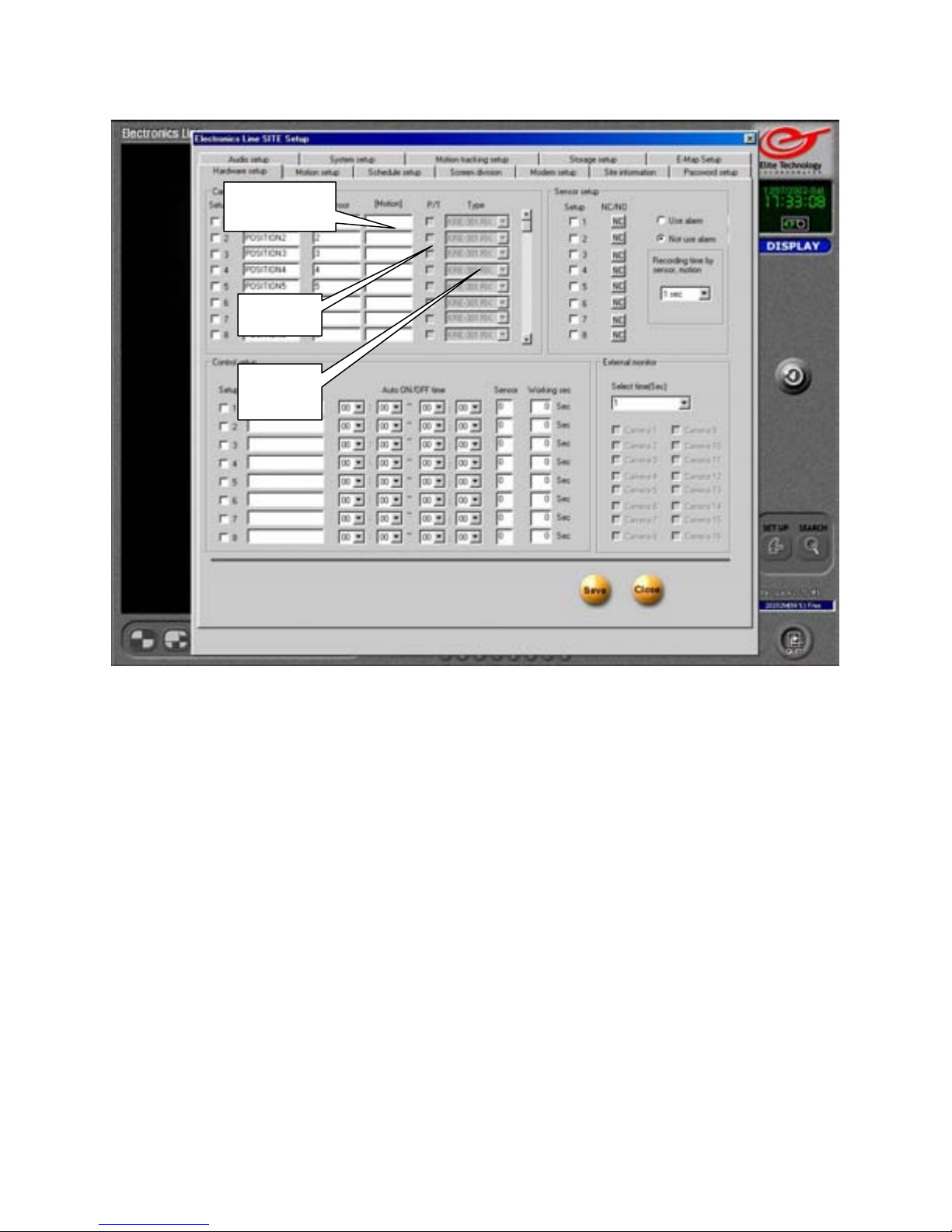
Setup
Name
Sensor
Camera Setup
Setup
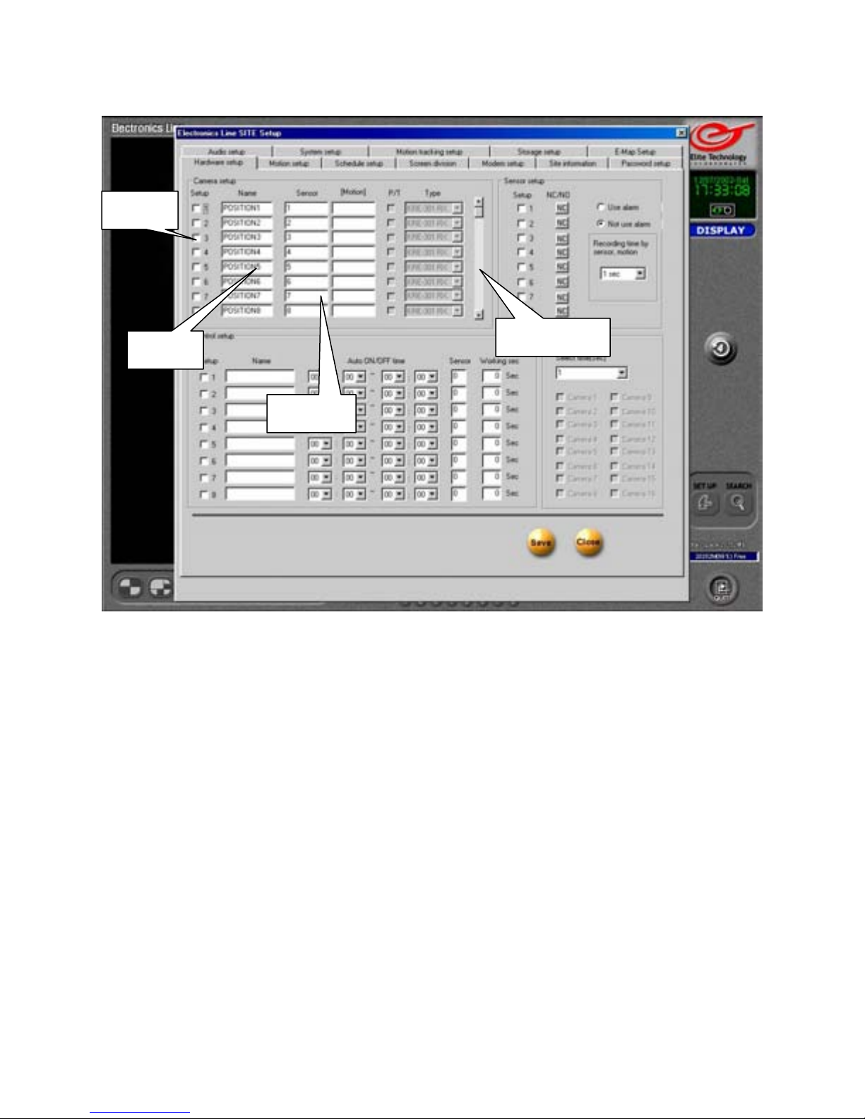
Check to enable camera, uncheck to disable
Use the scroll bar to view settings for cameras 9~16
Name
Enter name for each camera. You may use a maximum of 14 characters. This name will
appear on the main screen and in the recorded image.
Sensor
Sensors can be associated to cameras. The associated camera will begin recording when the
sensor is tripped.
Sensors must be enabled in sensor setup to use this function.
Enter the sensor number you want to associate in the sensor box. If you want more than
one sensor to activate the camera, use a comma to separate the numbers.
(Example) Enter 2,4,5 in the box for camera 1. Camera 1 will now record when sensors 2,
4, or 5 are activated.
Scroll Bar
11
Page 12
Hardware Setup
Motion
You may associate cameras to cameras. If you wish another camera to trigger camera 1,
enter that camera number in the “Motion” box for camera 1. Multiple cameras must be
separated by a comma.
Example: Enter 2,3,4 in the “Motion” box for camera 1. Camera 1 will now record if
camera 2, 3, or 4 detect motion. (The camera detecting the motion will also record.)
P/T
Enable Pan/Tilt/Zoom camera function by placing a check in this box.
Make sure the camera ID matches the frame number it will appear in on the DVR.
(If camera 6 is a P/T/Z make sure the camera ID is set to 6 in the on-screen setup for that
camera. This is usually done with binary dip-switches on the camera housing)
Type
Click the drop down arrow to select the closest model and manufacturer of the P/T/Z
camera you are installing.
12
Motion
P/T
Type
Camera Setup
Page 13
Hardware Setup
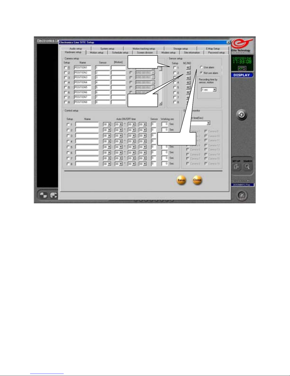
Setup
Place a check in the box to enable sensors if your DVR has sensor inputs.
(Sensor inputs are standard on Rack Mount units and optional on Desktop units)
If your unit does not have sensor inputs then do not use this function.
NC/NO
Set the type of sensor to “Normally Closed” or “Normally Open” by clicking on the button.
The button label will change to N/C or N/O to indicate how it is set.
Use Alarm
Place a check in the “Use alarm” button if you want to enable the DVR to use the ‘Sensor
for Emergency’ (in Modem Setup section) to transmit an image from the associated camera
to the remote, or ‘Center’ computer.
Setup
NC/NO
Use Alarm
Sensor Setup
13
Page 14
Hardware Setup
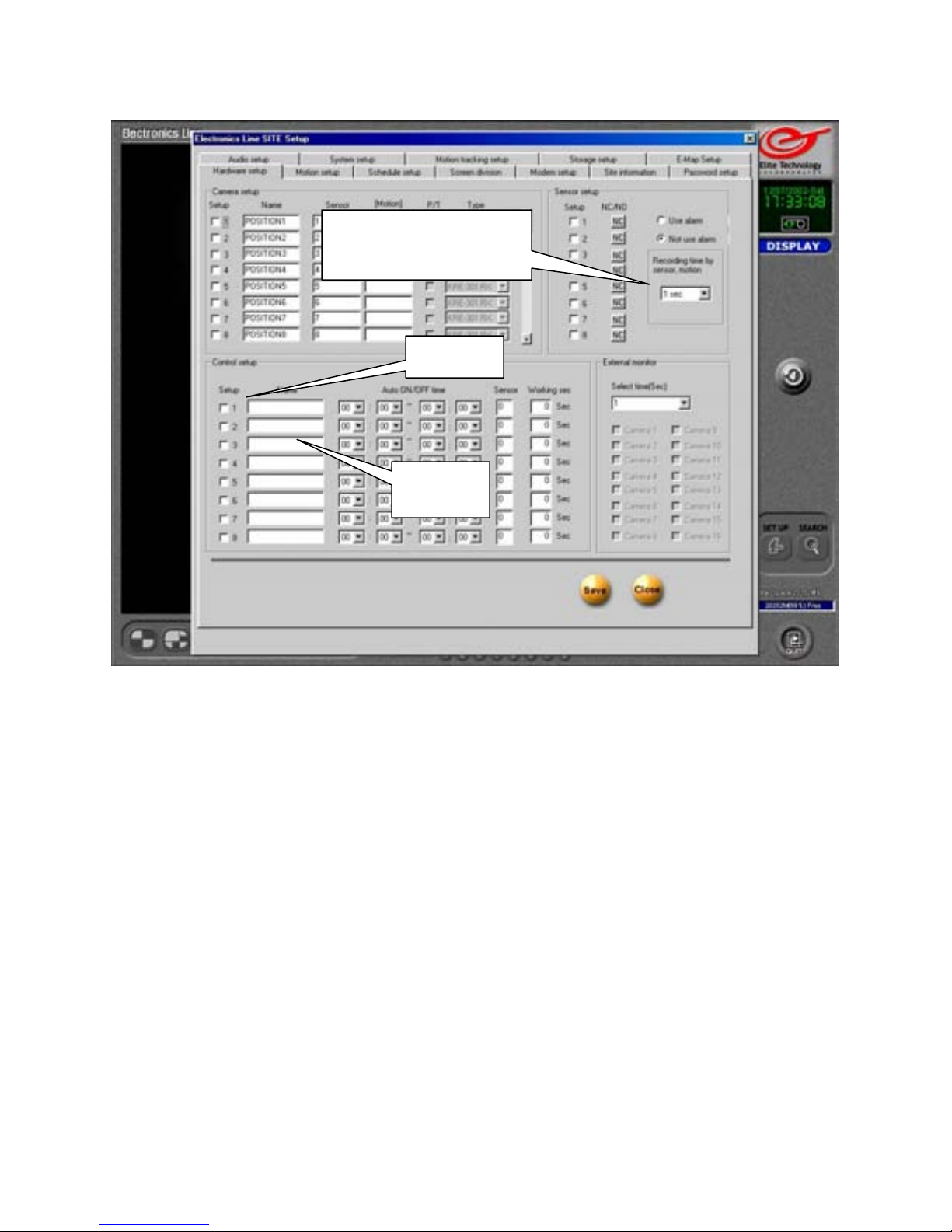
Recording time by sensor, motion
Choose how long the DVR will continue to record images after motion has been detected.
Use the drop-down arrow to select time in seconds.
Be aware that longer time settings will use more hard drive space and reduce your total
storage time. (Amount of time before DVR begins to overwrite oldest data.)
Setup
Place a check in the box to enable control relays if your DVR has relay outputs.
(Control relays are standard on Rack Mount units, optional on Desktop Units)
Name
Enter a name (location or device type) for each control relay. Use up to 14 characters.
Recording time by
sensor, motion
Setup
Name
Control Setup
14
Page 15

Hardware Setup
Auto ON/OFF Time
Enter start and end times to limit the time control relays can be activated. (Use 24-hour
time format) Default time is 00:00 to 00:00 (midnight to midnight or, always on.) Use the
drop down arrows to select hours and minutes. Control relays can be activated only within
the time specified. Activity outside the specified time will not trigger the control relay.
Example: To allow the control relay to activate an alarm only between 5:30pm and 8:00am
the next morning, enter 17:30 ~ 08:00.
Sensor
Associate a Sensor to trigger the Control relay.
(Example) Enter a 3 in the sensor box for control relay 1. Sensor 3 will now trigger control
relay 1.
Working sec
Select how long (in seconds) the Control relay will remain active after being triggered by a
sensor.
Auto ON/OFF
Time
Sensor
Working sec
Control Setup
15
Page 16
Hardware Setup
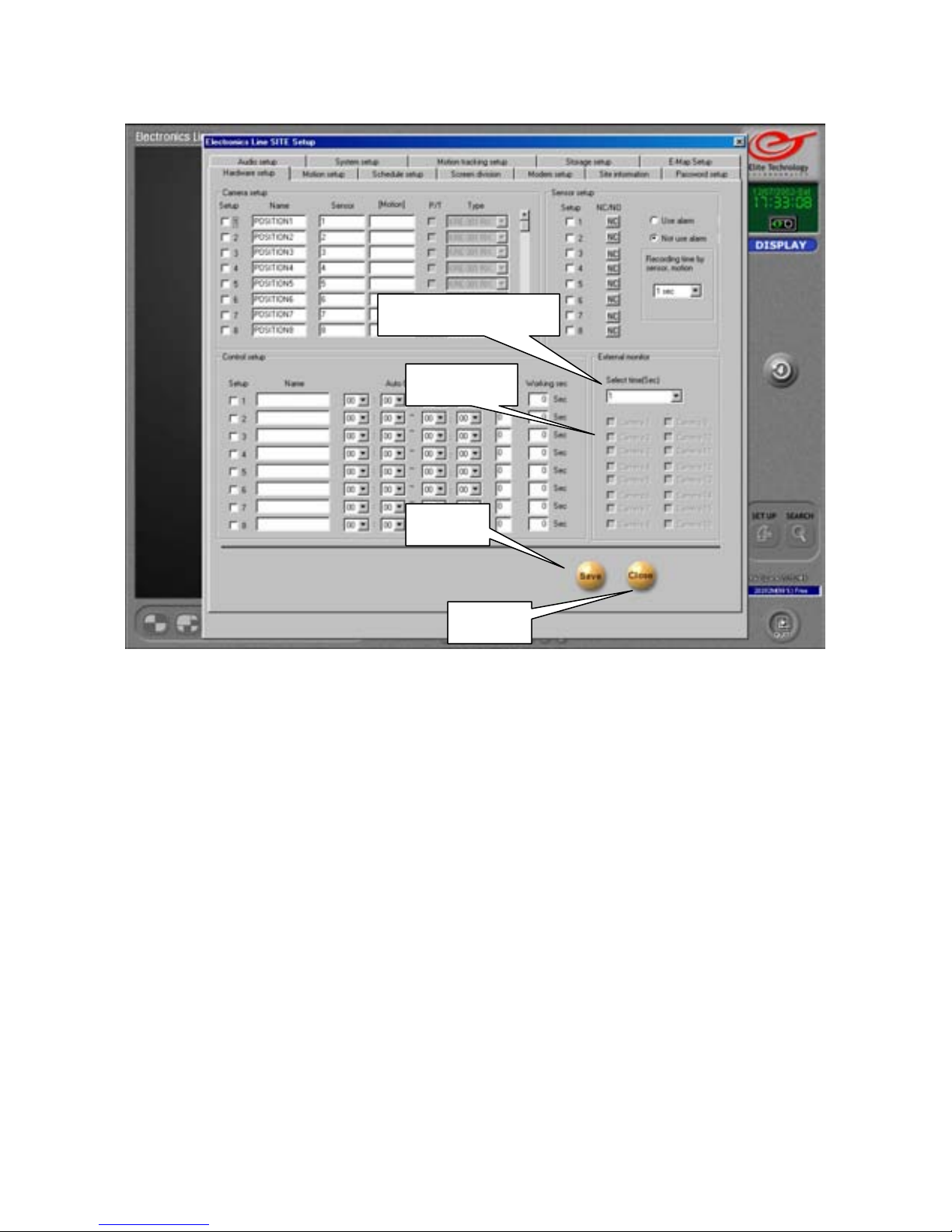
This setting refers to the optional NTSC spot monitor, not the DVR’s main screen.
Select time (sec)
Select length of time each image will remain on screen before next image appears on
external monitor. (Images appear in rotation on the external monitor)
Cameras
Select which cameras will appear in rotation on the external monitor by placing a check in
the box for that camera.
Save
Click to save your settings
Close
Click to leave setup and return to the Main Screen
Select time (Sec)
Cameras
Save
Close
External Monitor
WARNING: Save your settings before closing or switching
to another Setup Page. Your changes will be lost if you
16
forget to Save first.
Page 17
Motion Setup
Camera
Setup for Individual Cameras
Camera
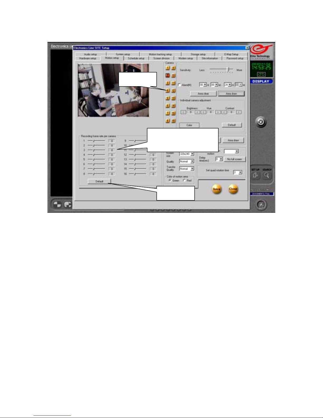
Select the camera you want to adjust by clicking on the numbered button. The live image
from that camera will appear in the Image screen. When you have finished setting up one
camera, click the button for the next camera you want to adjust. Each camera may be fine
tuned individually for sensitivity, detection area, brightness, hue, contrast, type (color or
monochrome), and recording frame rate.
Recording Frame Rate per Camera
Select the frame rate in “Images per Second” for each camera. This is the number of
“pictures” the camera will take and store every second the camera is activated.
(To increase the frame rate for a camera, you may have to decrease the rate for a different
camera. The total rate of all cameras can not exceed the total rate of the capture card. The
total frame rate of the card is indicated by the first two numbers in the DVR’s model
number.)
Example: Model ET-80-16 = 80 images per second capture rate, 16 cameras. Divide 80
images per second by 16 cameras to get a frame rate of 5 images per second per camera.
Default
Click this button to reset the recording frame rate to the maximum averaged rate for all
cameras. (Maximum rate of capture card divided by number of cameras)
Recording frame
rate per camera
Default
17
Page 18
Motion Setup
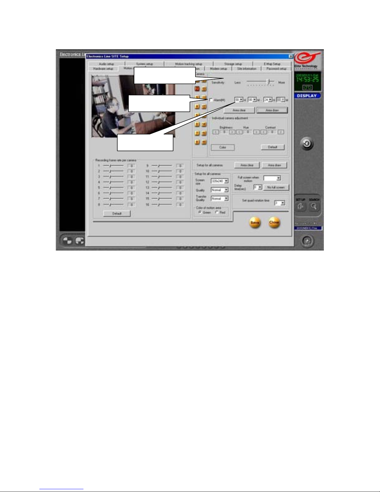
Sensitivity
Adjust the sensitivity of the motion detection grid for each camera. If a camera is recording
when there is no apparent motion, decrease the sensitivity by moving the slider to the left.
This will help extend your total recording time by reducing the number of “false alarms”.
Alarm (M)
Place a check in the box if you want the DVR to emit a “beep” sound from its internal
speaker when motion is detected.
Time
If you want the alarm function to be active only during certain hours, enter the start and
end times here. Enter the time in 24 Hour format.
(Example) For 8:00am to 5:00pm you would enter 08 ~ 00 to 17 ~ 00.
Sensitivity
Alarm
Time
Setup for Individual Cameras
18
Page 19
Motion Setup
Left click and
drag the cursor
diagonally to
create a grid
Setup for Individual Cameras
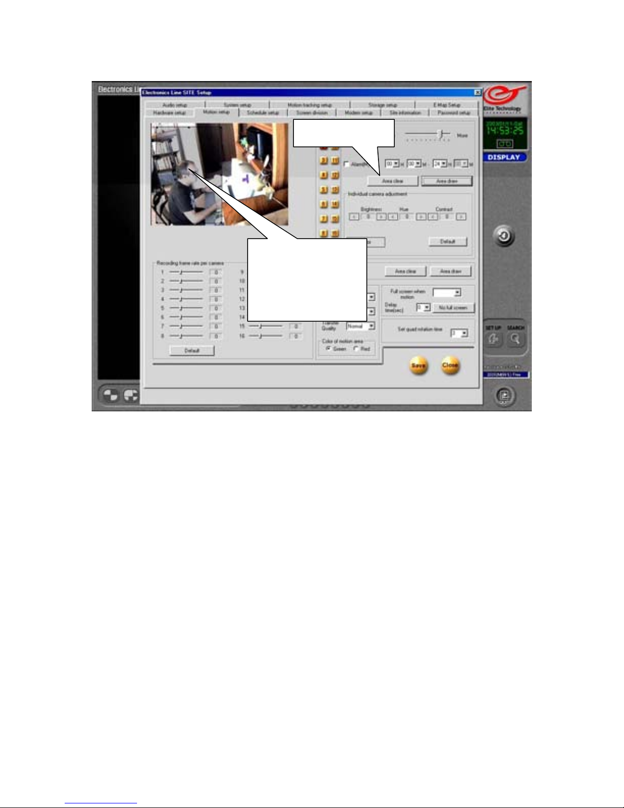
Area Clear
Removes motion detection grid from frame so you may customize the detection zones and
“mask” around objects that move or flicker constantly.
Select the “Area Clear” button, place your cursor over the image, click and hold the left
mouse button while you move the cursor diagonally. This will produce a box with a motion
detection grid inside it. You may “resize” the box by holding the cursor over the small
squares around the perimeter until the cursor turns into an arrow ( ÅÆ ), then click and
hold the left mouse button while you move the cursor.
Hint: Grab the corner squares to resize horizontally and vertically at the same time.
You may draw up to 5 areas per camera.
Click on a grid and press “Delete” on your keyboard to remove it.
Click “area clear” again at any time to clear all grids from the camera and start over.
The outline of the areas you create will appear on the main screen when motion is detected.
(The outlines will not appear on the recorded image)
The entire frame is recorded when any area detects motion.
Area Clear
19
Page 20
Motion Setup
Area Draw
Brightness,
Hue,
Contrast
Color /
Monochrome
Default
Setup for Individual Cameras
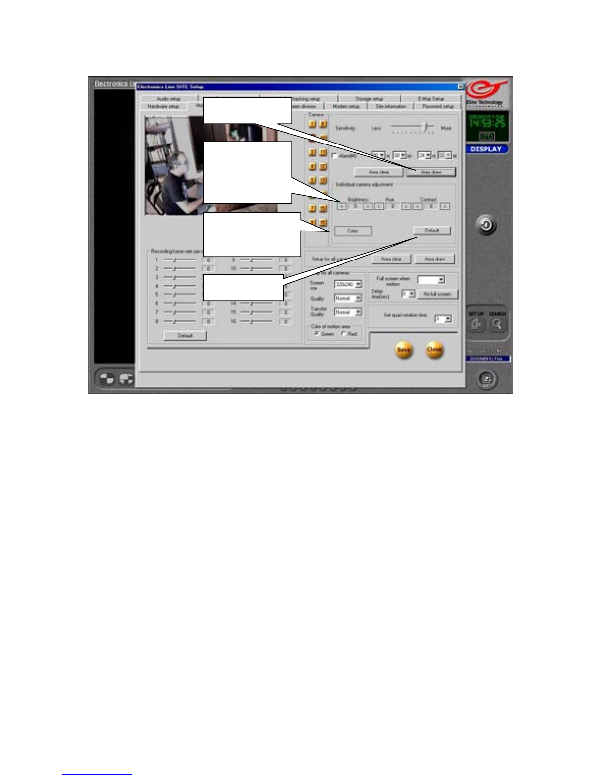
Area Draw
Places a grid over the entire image so the entire frame is motion sensitive.
Click on the ‘Area Clear’ button and look at the image on the left. Now click on the ‘Area
Draw’ button and look at the image. Notice the black diagonal lines that appear. This is
your ‘Motion Detection Grid’.
Brightness, Hue, Contrast
Adjust the image quality of each camera to obtain the best picture.
Brightness: Adjusts overall shade of image from light to dark.
Hue: Adjusts color bias of image.
Contrast: Adjusts amount of difference between light and dark areas.
Color/Monochrome
Selects whether a camera is color or monochrome. (Black and White)
This is especially important if you have both color and black and white cameras connected.
(Colors on all cameras may look odd or exaggerated until they are identified properly.)
Default
Return Brightness, Hue, Contrast, and color/monochrome settings to factory default
values.
20
Page 21

Motion Setup
Area Clear
Screen Size
Quality
Transfer Quality
Setup for All Cameras
Area Clear
Removes the motion detection grid from all cameras.
Area Draw
Draws motion detection grid across entire frame on all cameras.
Screen Size
Select the image size to be recorded. 640x480 is the largest image, 160x120 is the smallest.
320x240 is the default size. Remember that larger images create larger file sizes and affect
overall recording time.
Quality
Select the image quality to be recorded from “Lowest” to “Best”. Higher quality settings
also create larger file sizes and affect overall recording time.
Transfer Quality
Set quality of images to be transferred over network or modem connections. For slower
modem connections, use low quality to improve transmission speeds.
Area Draw
21
Page 22
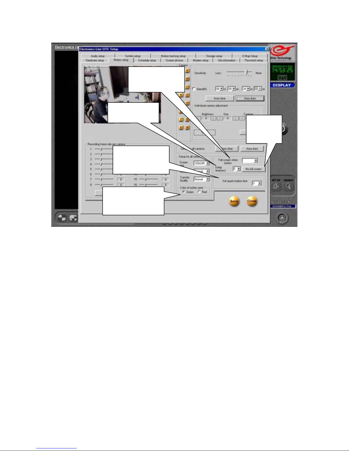
Motion Setup
Full Screen
When Motion
Delay Time
Set Quad
rotation Time
Color of
motion area
Setup for All Cameras
Full Screen when Motion
Select cameras that will jump to full screen view (on the main surveillance screen) when
motion is detected. Separate multiple camera numbers with a comma.
Example: To set cameras 1, 3, and 5 enter 1,3,5
Delay Time (sec)
Set the length of time image will remain at full screen when motion is detected. Affects only
cameras enabled in “Full screen when motion” setting.
No Full Screen
Removes all cameras from “Full screen when motion” setting.
Set Quad Rotation Time
Set the length of time images remain on the Main Screen in Quad rotation when the ‘Quad
Rotation’ button is pushed. (The main screen will change to a 4 image split and rotate
through all active cameras 4 at a time.)
Color of Motion Area
Set color of motion grid outline that appears on main screen when motion is detected.
No Full
Screen
22
Page 23
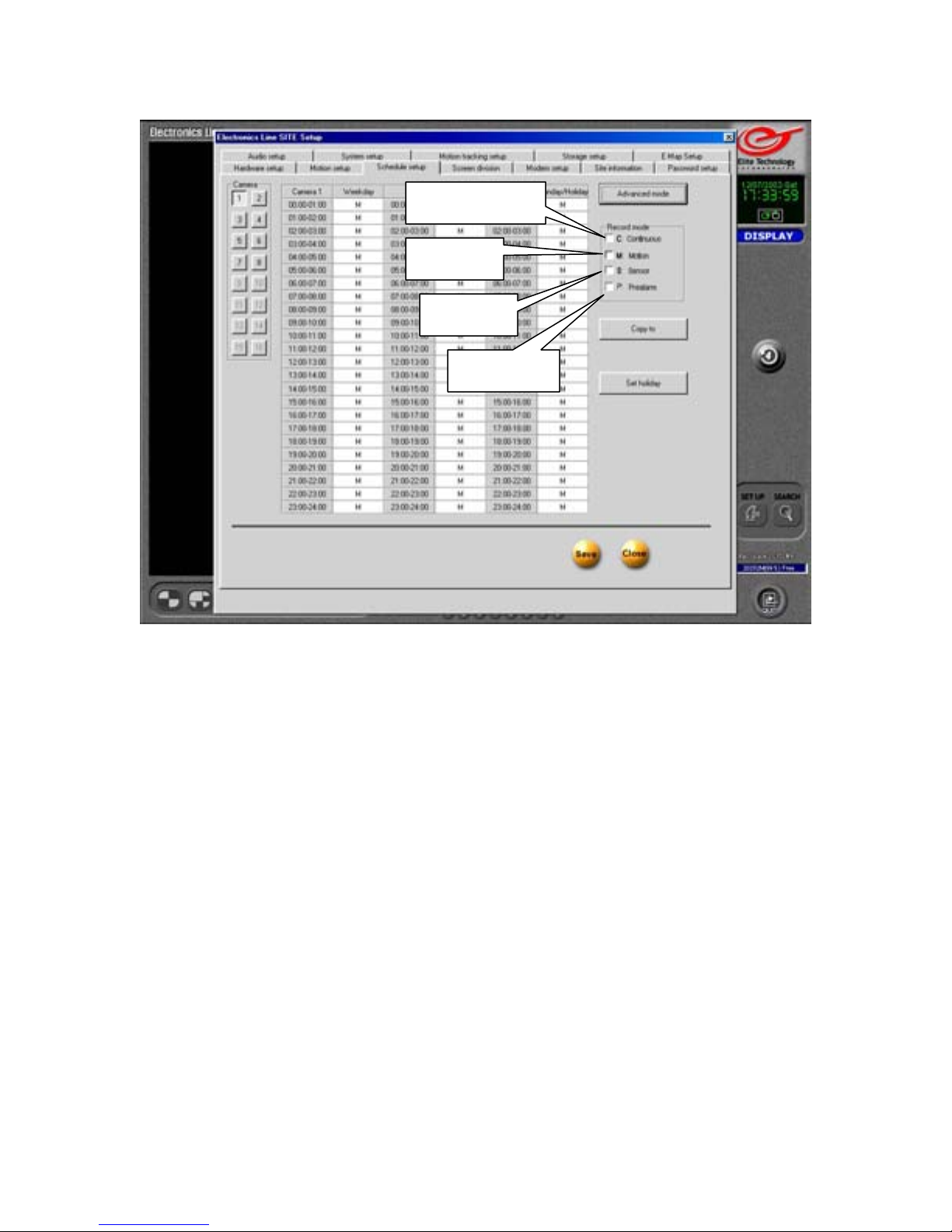
Schedule Setup
Continuous
Motion
Sensor
Prealarm
Schedule setup allows you to determine what mode your cameras will operate in at any
given time of day.
Continuous: Cameras will record continuously.
Motion: Cameras will record only when motion is detected.
Sensor: Cameras will record when triggered by associated sensors.
Prealarm: Cameras will record events up to 5 seconds before motion is detected.
Place a checkmark in the box to enable the mode(s)
Removing the checkmark from all four options will set the camera to “Look Only” mode.
(No video will be recorded)
You may use more than one mode on each camera.
Supported modes include:
Look Only (No record)
Continuous Record (Disables Motion, Sensor, and Prealarm functions)
Motion
Sensor
Motion + Sensor
Motion + Prealarm
Sensor + Prealarm
Motion + Sensor + Prealarm
23
Page 24
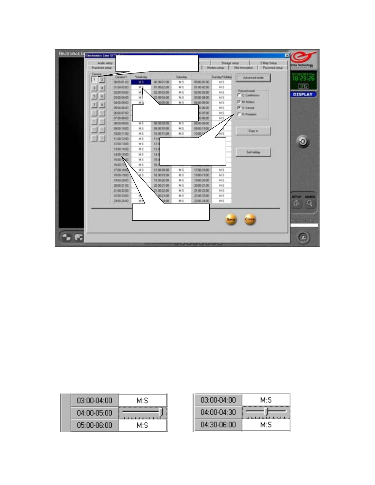
Schedule Setup
Select a Camera
Select Time
Select Record
Mode
Adjust minutes
1. Select a Camera: Each camera’s schedule may be set individually.
2. Select Time: Select hour(s) Left click to select a single hour. Left click and hold
the button down while you move the cursor to select more than one hour. Or click
on the ‘Select All’ button at the top of the timeline to select ALL hours in that
column. (The button in column #1 says ‘Camera 1’. In ‘Simple’ mode, all days will
be selected when you click this button.)
3. Select Record Mode: While the hour(s) you selected are highlighted, select the
mode(s) you wish to use for that time period.
4. Adjust Minutes: Click on the grey “Hour” button to adjust the minutes. A slider
will appear. Left click and hold to move the slider. The “Hour” button will change
to show the minutes you select. (The following hour will automatically adjust also.)
24
Page 25
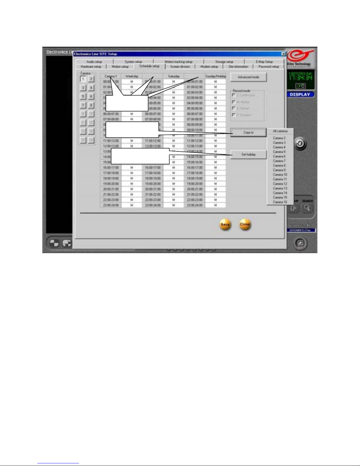
Schedule Setup
Select All
Copy To
Set Holiday
Select All
Click on the ‘Select All’ buttons to select all the hours in that column.
Copy To
Once you have created a schedule for one camera, you may copy it to any other camera.
Select the “Copy to” button, then click on the camera number you want to copy the
schedule to. You may copy the schedule to as many cameras as you wish.
Click on “All cameras” to copy schedule to all cameras at once.
Set Holiday
You may select any Weekday or Saturday to be designated as a “Holiday”.
Sundays and Holidays are treated the same in the schedule. The schedule you have set up
under the “Sunday/Holiday” column will be applied to any day you select as a Holiday.
Click on Set Holiday to open the Holiday setup panel.
Remember to SAVE your settings before closing
25
Page 26
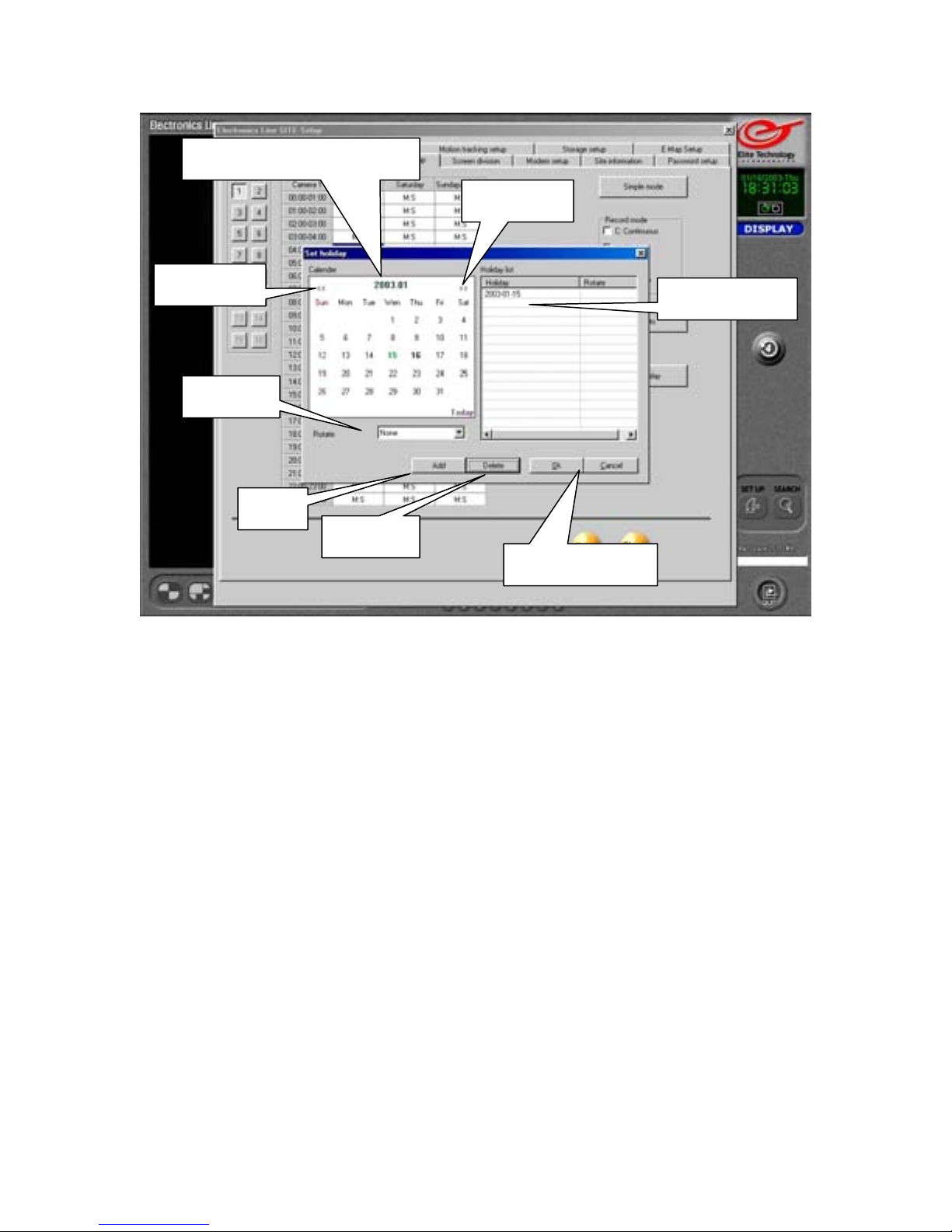
Schedule Setup
Select Month and Day
Arrows
Arrows
Added Days
Rotate
Add
Delete
Ok / Cancel
Holiday Setup
Select Month and Day
Use the “Arrows” to select the month. Then left click on the day on the calendar to select it.
Rotate
You have the option to add the selected day to a repeating pattern.
Monthly: The same day will be set as a holiday every month.
Yearly: The same day will be set as a holiday every year.
None: The selected day will be treated as a holiday one time only.
Add
Add the selected day to the Holiday schedule. Date will appear in the “Added Days” list
along with selected “Rotate” option.
Delete
Select a date in the “Added Days” list and click Delete to remove it.
Ok / Cancel
Click “OK” to save your changes, or “Cancel” to return to Schedule Setup without saving
any holiday setup changes.
26
Page 27
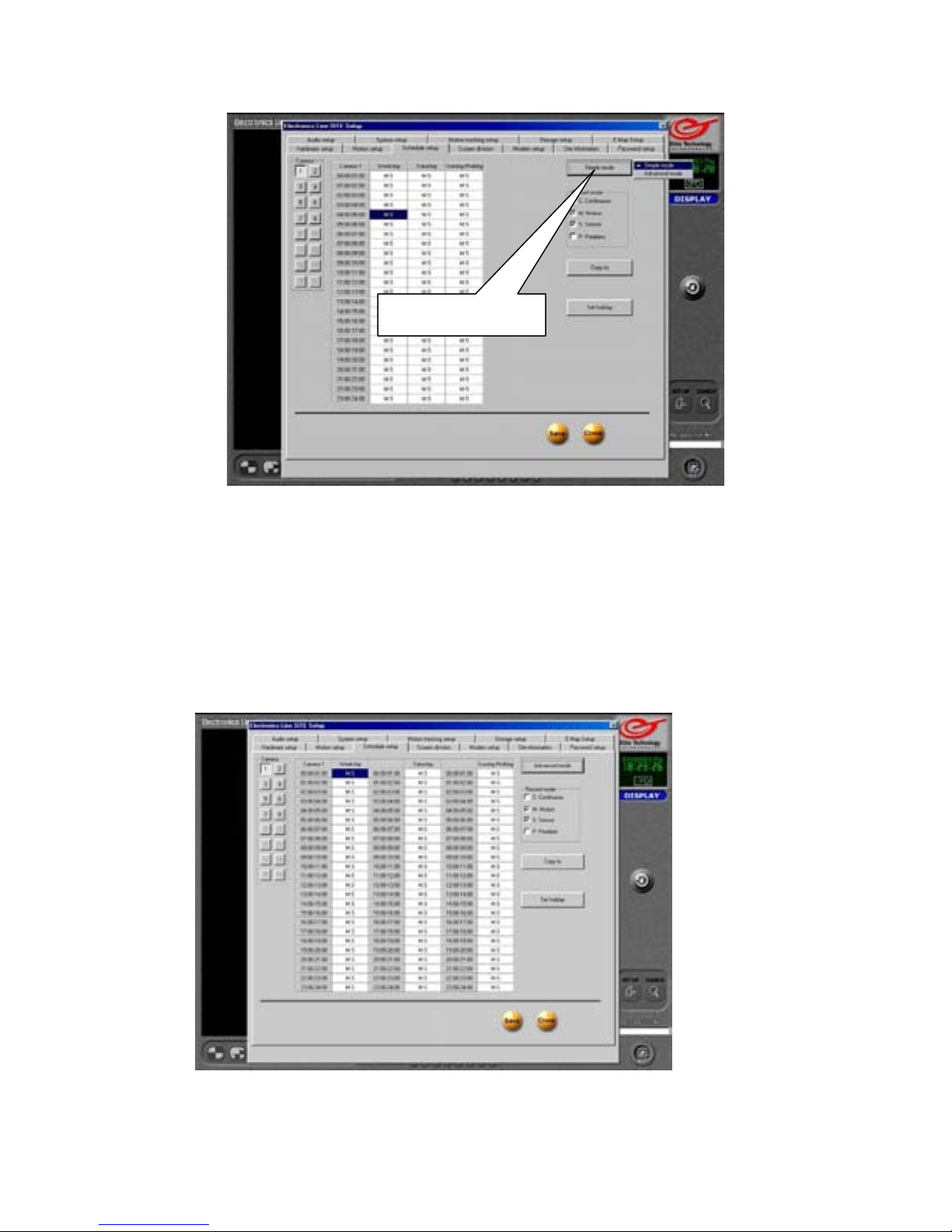
Schedule Setup
Mode Button
Simple Mode
Mode Button
Toggle between “Simple” and “Advanced” schedule by clicking the “Mode” button and
selecting the schedule setup mode you prefer.
In “Simple” mode, all days (Weekdays, Saturdays, and Sunday/Holidays) are set on a
single 24 hour timeline. Any time adjustments you make will apply to all days.
In “Advanced” mode, Weekdays, Saturdays, and Sunday/Holidays each have their own 24
hour timeline.
Advanced Mode
27
Page 28
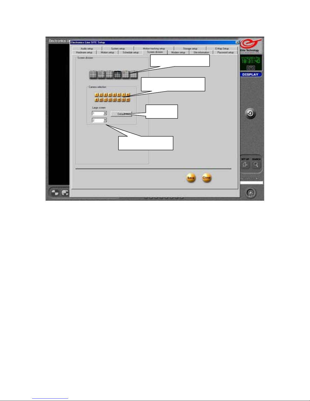
Screen Division
Screen Division
Camera Selection
Default
Large Screen
Screen Division
Select the screen division you prefer to display on the VGA monitor. The settings you
choose will become the default view on the Main Screen.
Camera Selection
Enable or disable cameras on the selected screen division. Disable cameras you do not want
to appear on the Main Screen. Disabled cameras will be replaced by the Elite Technology
logo.
Default
Returns settings for the selected screen division to factory defaults. (All cameras on)
Large Screen
Assign which cameras will appear in the large screen(s) in the 6, 10, and 13 division
views.
Remember to SAVE your settings before closing
28
Page 29
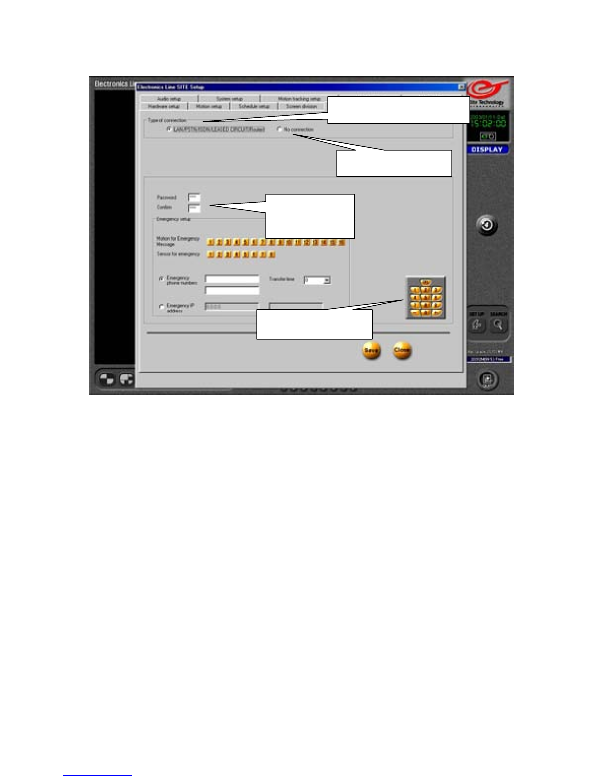
Modem Setup
Type of Connection
No Connection
Password /
Confirm
Virtual Keypad
Type of Connection
Click “LAN/PSTN/ISDN/LEASED CIRCUIT/ROUTER” if you have the DVR installed on
a LAN (Local Area Network) or if you use the optional 56K modem to provide remote
access to a computer with the “Electronics Line Center” software installed.
No Connection
Select “No Connection” if you do not plan to remotely monitor the DVR.
Password / Confirm
Set the password for incoming connections from your remote computer.
Password must be 4-digit numeric (only 4 digits, all numbers). Use the keyboard or you can
use the mouse to select numbers on the “Virtual Keypad”.
The default password for incoming connections is: 1234
29
Page 30
Modem Setup
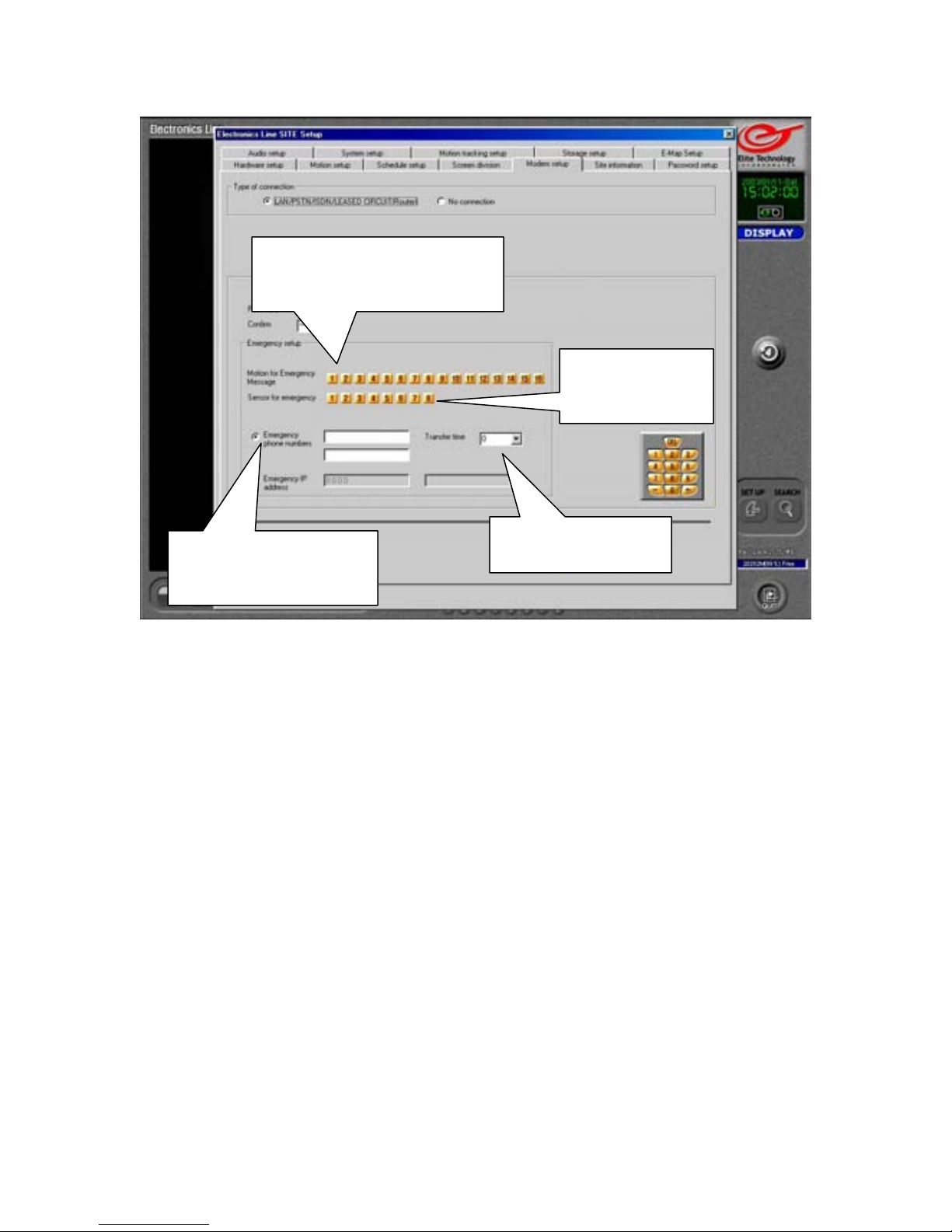
Motion for Emergency
Message
Emergency Phone
Numbers
Motion for Emergency Message
Select cameras that will activate the Emergency Message function.
When motion is detected by a camera the DVR will capture the image and transmit it to
the remote, or “Center” computer.
Sensor for Emergency
Select the sensors that will activate the Emergency Message function. When a sensor is
tripped, the DVR will send an alarm to the remote, or “Center” computer. If the sensor is
associated to a camera (in “Hardware Setup”) the DVR will also send the captured image.
Emergency Phone Numbers
If you use a modem to connect the DVR to the remote, or “Center” computer, then
enter the phone numbers of the remote, or “Center” computer(s) that the DVR will send
the emergency message to. If the DVR fails to connect to the first number, it will dial the
second number and attempt to transmit the message.
Transfer Time
Set the time (in seconds) that the modem will keep the connection to the remote computer
open and active. Any image captured by selected cameras during that time will also be
transmitted.
Sensor for
Emergency
Transfer Time
30
Page 31
Modem Setup
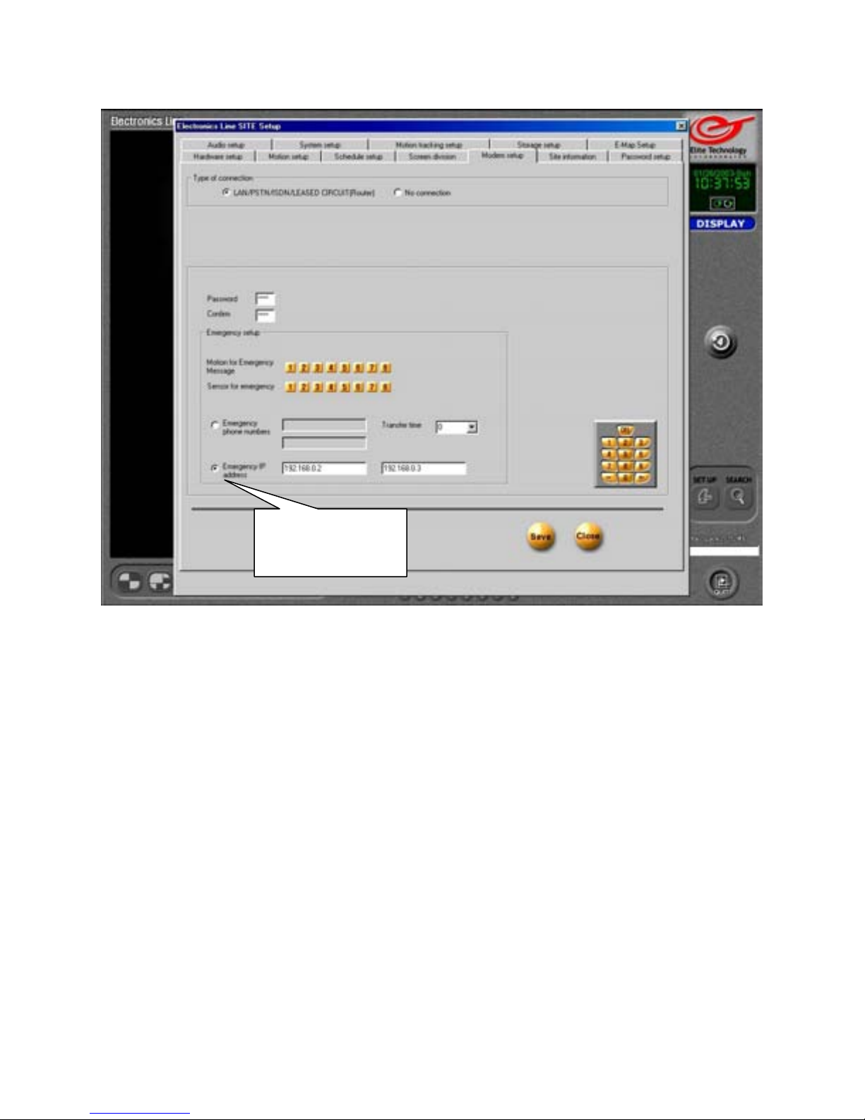
Emergency IP
address
Emergency IP Address
If the DVR is connected to a LAN (Local Area Network) or to the Internet through a DSL
or Cable Modem connection, you can assign the IP (Internet Protocol) address of the
remote, or “Center” computer(s) you wish to receive the Emergency Message.
In order for this function to work correctly you must insure that the remote computer you
wish to transmit to is connected and available on the network or internet.
The easiest way to determine this is to use the Windows “ping” utility.
Remember to Save your settings.
31
Page 32
Modem Setup
Using the “Ping” Utility
To ensure that you have a good connection to the remote computer on the LAN (Local
Area Network) or WAN (Wide Area Network), use the “ping” utility.
The “ping” utility will transmit a small packet of data to the remote computer and wait for
a response.
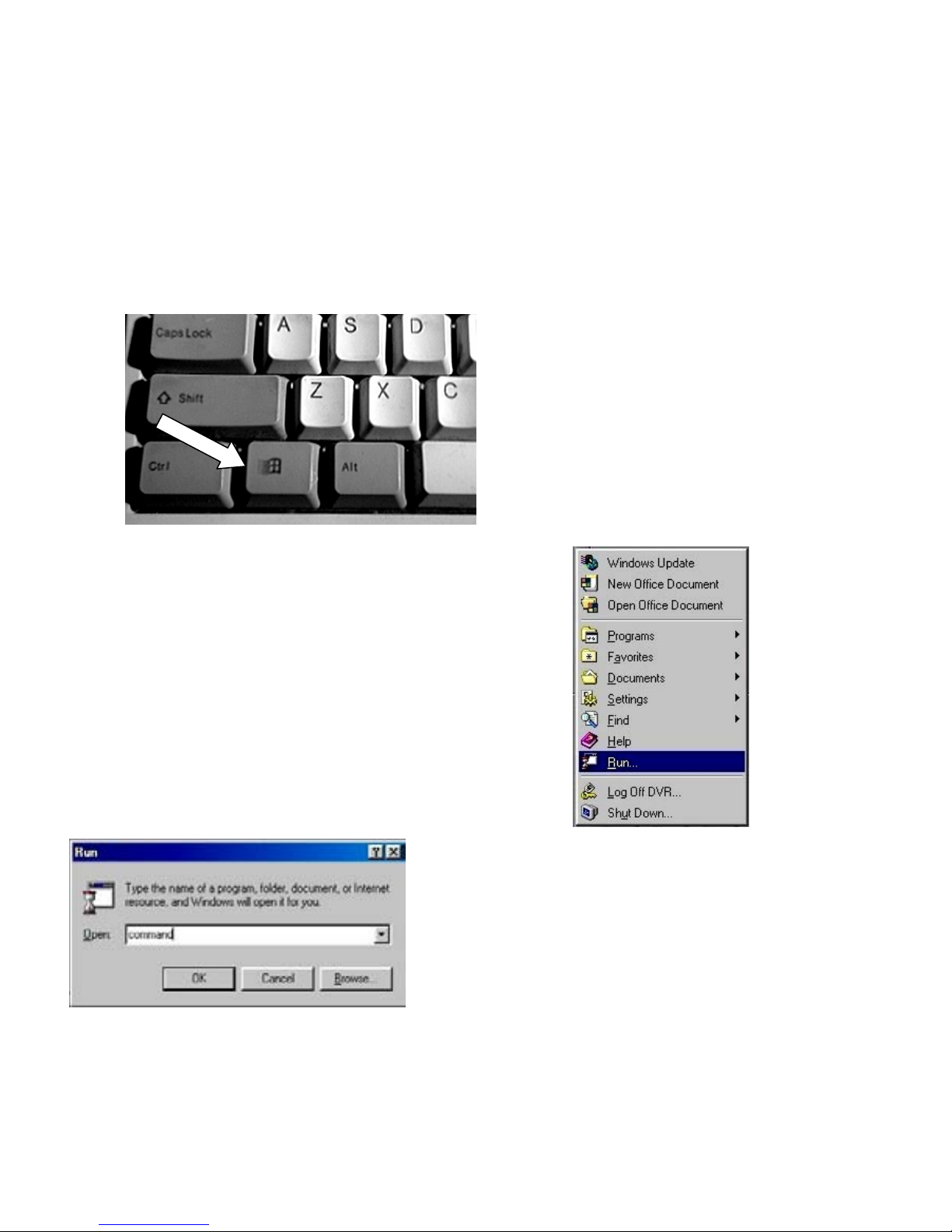
To use the “ping” utility:
Press the “Windows” key on your
keyboard (Between “Ctrl” and “Alt” on the
lower left) to bring up the Windows “Start”
menu.
On the Windows start menu, select “Run”
Type ‘command’ (without the quotes) in the box
that appears.
Either click “OK” or press “Enter” on your
keyboard
This will initiate the DOS command prompt on your screen.
32
Page 33
Modem Setup
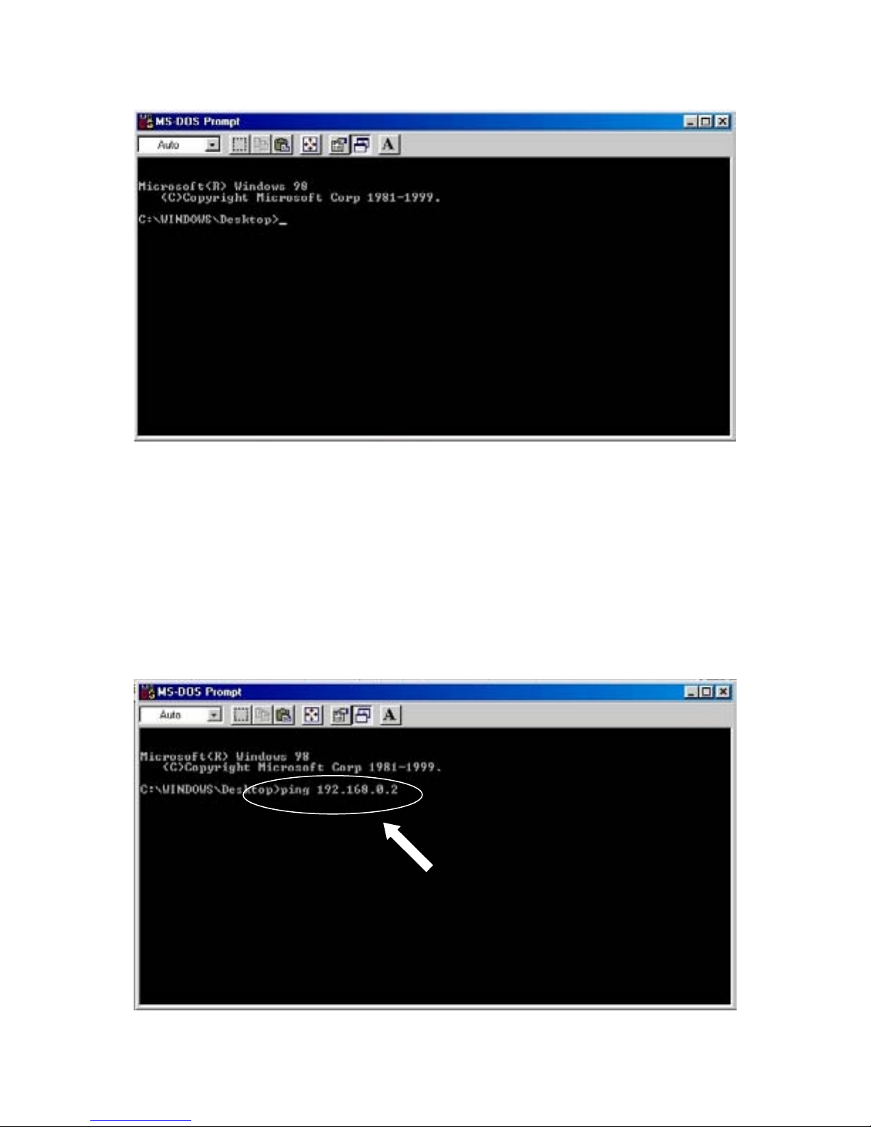
At the command prompt type in ‘ping’ (without the quotes).
Press the ‘Space’ bar once to leave a space.
Enter the IP address of the computer you wish to ping.
(Example)If the address of the computer you want to connect to is 192.168.0.2,
type: ping 192.168.0.2 (Remember to leave one space between ping and the address.)
Press ‘Enter’ on your keyboard.
33
Page 34
Modem Setup
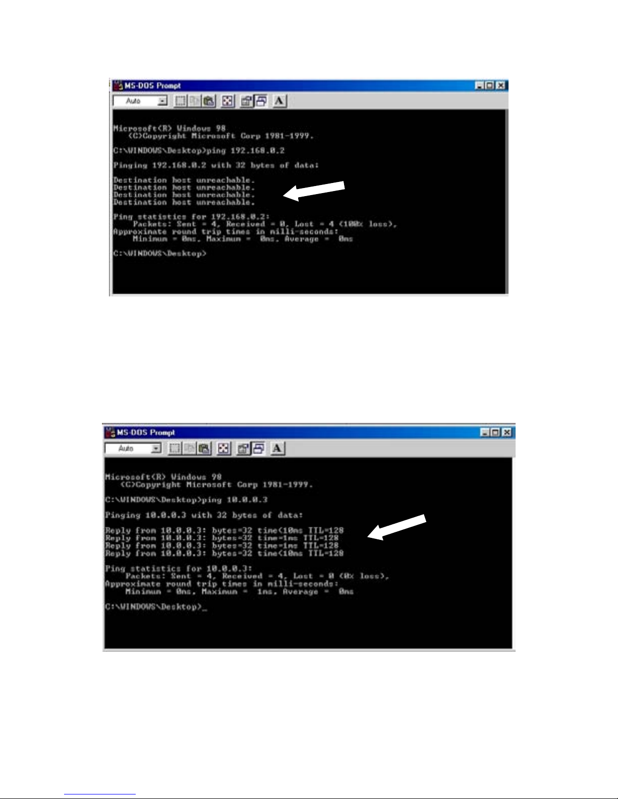
If you receive a “Destination host unreachable” reply, then your network is not configured
correctly or you may have the wrong IP address for the remote computer. Contact your
Network Administrator for help in getting the DVR connected to the network.
If your network is configured correctly and you have entered the correct IP address, you
should get a reply showing the remote computer’s address and the time (in milliseconds)
that it took to reply. This confirms your network connection to the remote computer.
Type in ‘exit’ (without the quotes) and press ‘Enter’ on your keyboard to exit the
command prompt.
34
Page 35
Modem Setup
If your DVR came with a modem installed, it is preconfigured to answer incoming calls
from the remote (Center) computer.
The default password for incoming connections is: 1234
If your DVR does not have a modem installed, you may have a qualified technician add one
for you. The modem must be compatible with ‘Windows98 Second Edition’.
If you purchase an ‘External’ modem you will not have to remove the outer case of the
DVR to install it, however, if you have Pan/Tilt/Zoom cameras controlled by the
RS-232 (serial) control port you will need to purchase a ‘USB’(Universal
serial Bus) modem since the ‘Serial’ port is already in use.
If you decide on an ‘Internal’ modem the technician will have to remove the outer case of
the DVR to install it.
If you are unsure how to remove the case, call DVR Technical Support for assistance.
8:30am ~ 5:30pm (Mountain time Zone) Monday through Friday
1-800-683-6835
Remember to TURN OFF the DVR and unplug it before
attempting to install an internal modem.
Follow the directions provided by your modem manufacturer to install your modem and
drivers. Use the instructions and drivers for ‘Windows98 Second Edition’.
Once you have the modem installed you will need to configure it correctly to receive
incoming calls from the ‘Center’ computer.
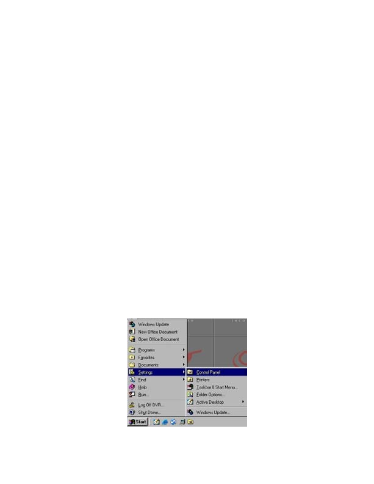
Press the ‘Windows’ key on your keyboard (Between ‘Ctrl’ and ‘Alt’ on the lower left) to
bring up the Windows ‘Start’ menu.
Choose ‘Settings’ and then ‘Control Panel’.
35
Page 36
Modem Setup
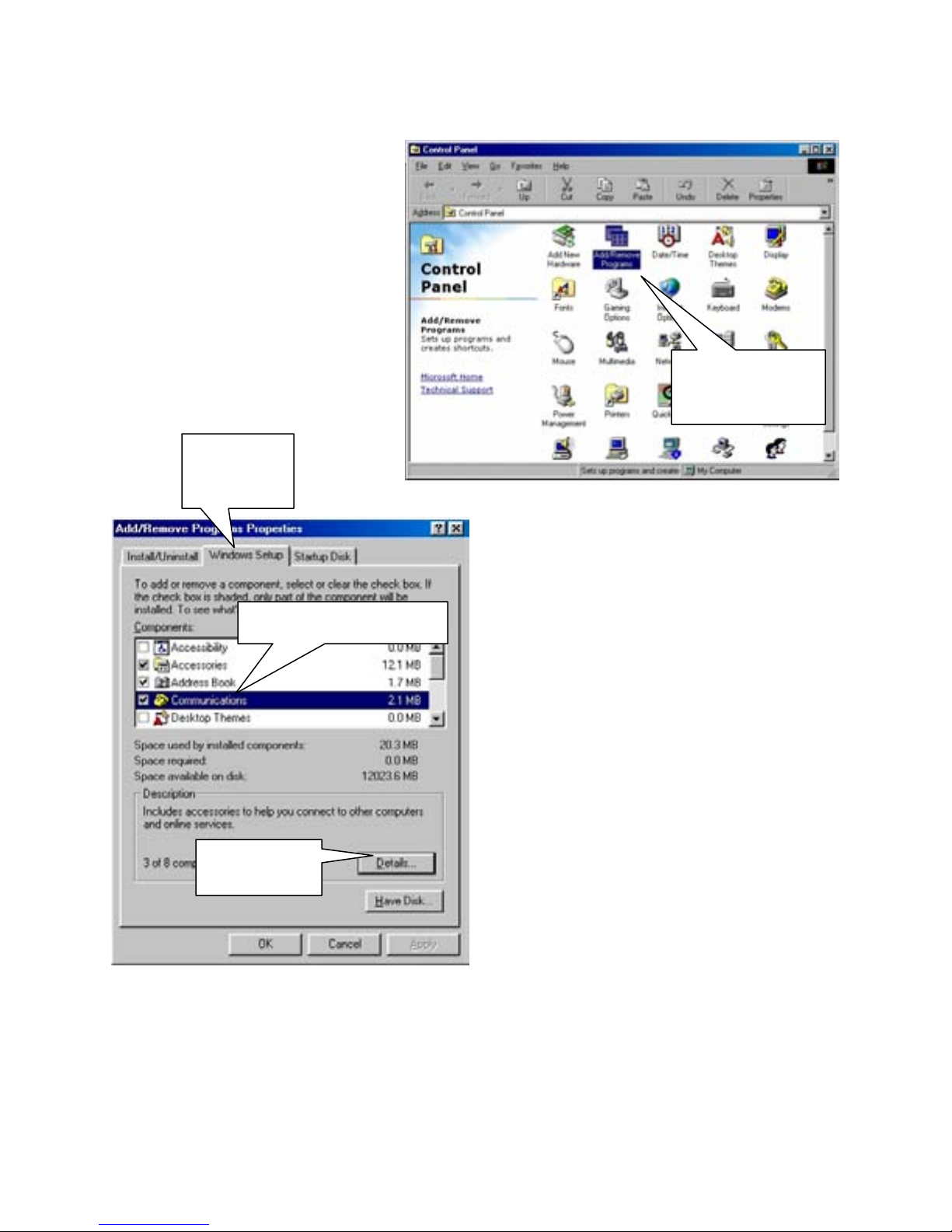
When the Control Panel appears,
choose “Add Remove Programs”.
Communications
Details
36
Windows
Setup
Add Remove
Programs
When the ‘Add Remove Programs
Properties’ box appears, choose the
‘Windows Setup’ tab.
When ‘Windows Setup’ appears, click on
‘Communications’. If there is not a check in
the box next to ‘Communications’, place one
there now.
Click on the ‘Details’ button.
Page 37
Modem Setup
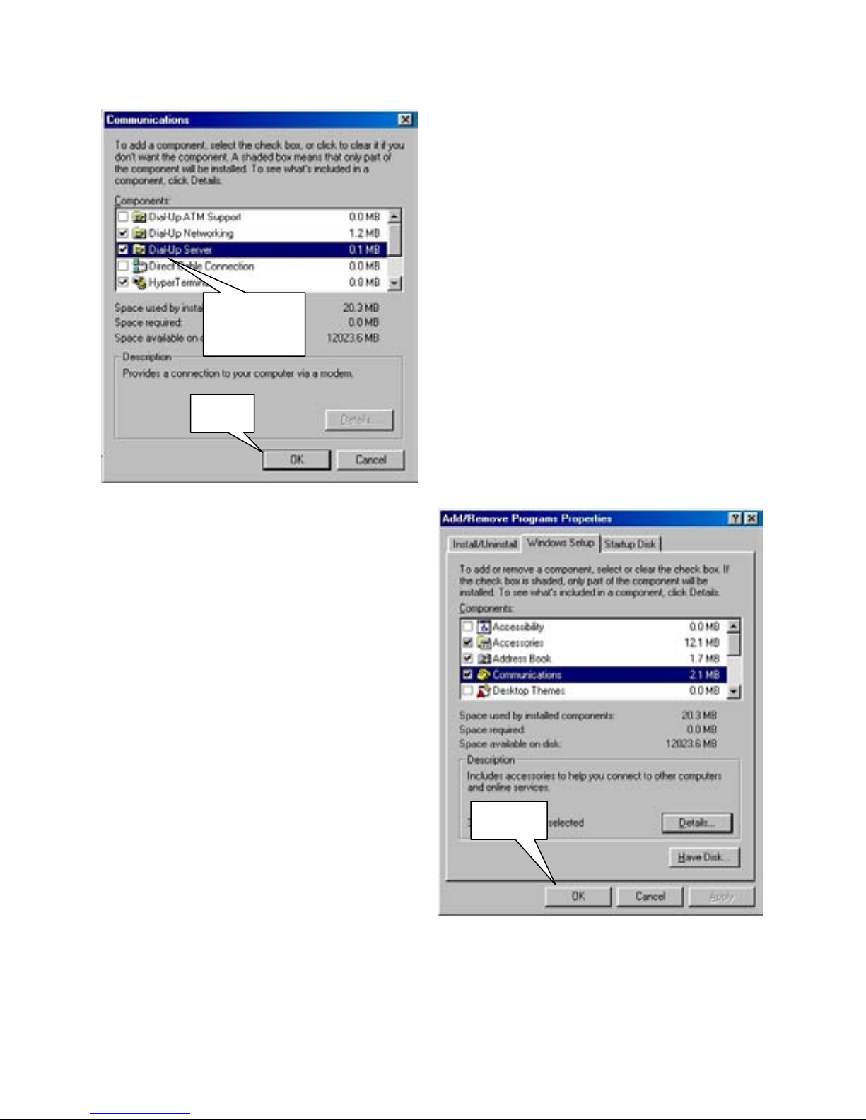
Dial-Up
Server
OK
Click on ‘OK’ again to install Windows
Dial-Up Server.
You may be asked for the ‘Windows98
Second Edition’ installation disk.
This should be with the software package
you received with the DVR.
Place the disk in the CD tray and browse to
the Win98se folder to complete the
installation.
Windows may need to reboot the DVR to
finish installing your modem.
(If Windows Dial-Up Server is already
installed you may skip this procedure and
move to the next step.)
When the ‘Communications’ details box
appears, place a check in the box next to
‘Dial-Up Server’.
Click on ‘OK’
OK
37
Page 38
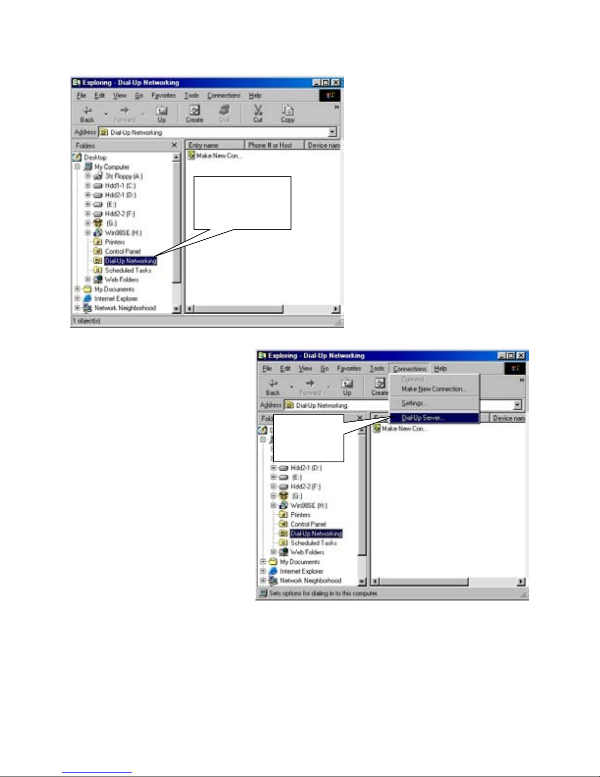
Modem Setup
Dial-Up
Networking
From the menu at the top of the
window click on ‘Connections’ and
choose ‘Dial-Up Server’ from the
drop-down menu.
38
Press the ‘Windows’ key on your
keyboard,(between ‘Ctrl’ and ‘Alt’
on the lower left) and ‘E’ at the
same time to bring up ‘Windows
Explorer’.
Click on ‘Dial-Up Networking’
Dial-Up
Server
Page 39
Modem Setup
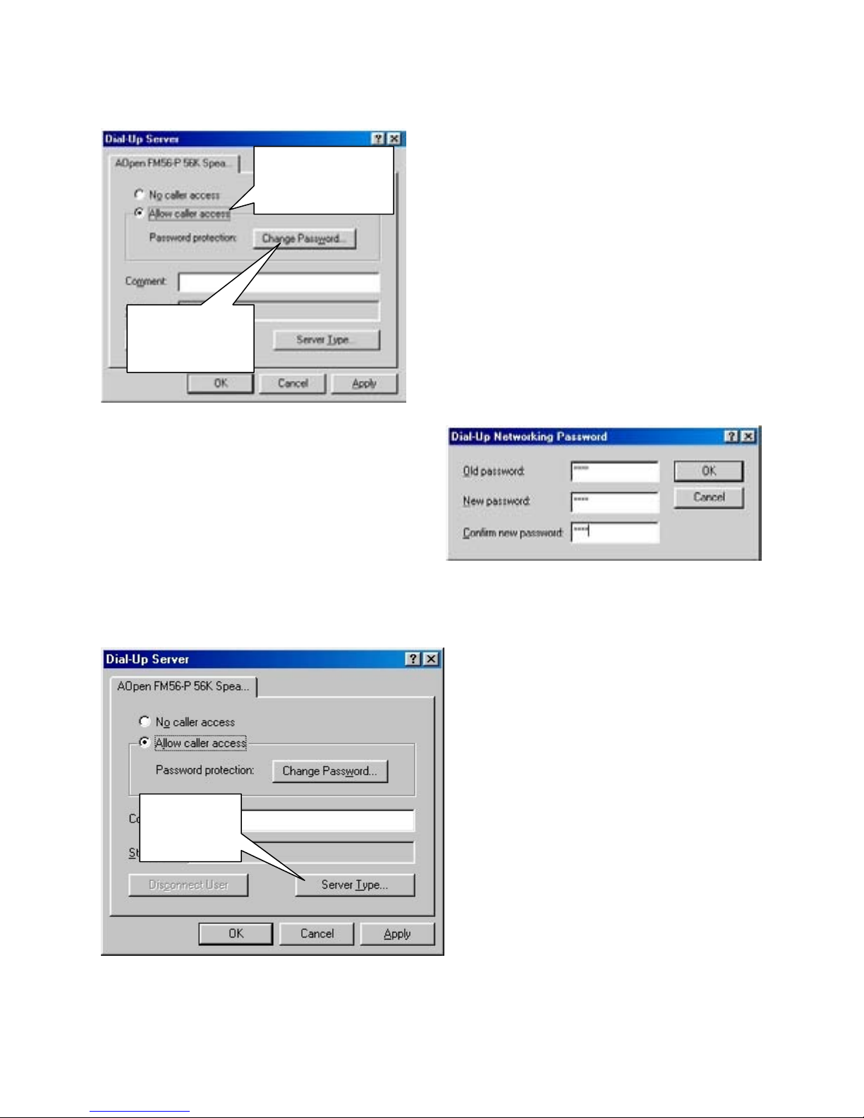
Allow caller
access
Change
Password
Type in a 4 digit numeric password.
(4 digits, all numbers)
Click on ‘OK’ to finish.
The default password is: 1234
If you use a different password, you
must also enter it in the ‘Modem Setup’ section of the DVR software under
‘Password’ and ‘Confirm’
.
Server
Type
When the ‘Dial-Up Server” properties box
appears, place a check in the button next to
‘Allow caller access’.
Then click on the ‘Change Password’ button to
set the password for incoming calls.
After setting the password, you will
automatically return to the “Dial-Up
Server’ properties box.
Click on the ‘Server Type’ button
39
Page 40
Modem Setup
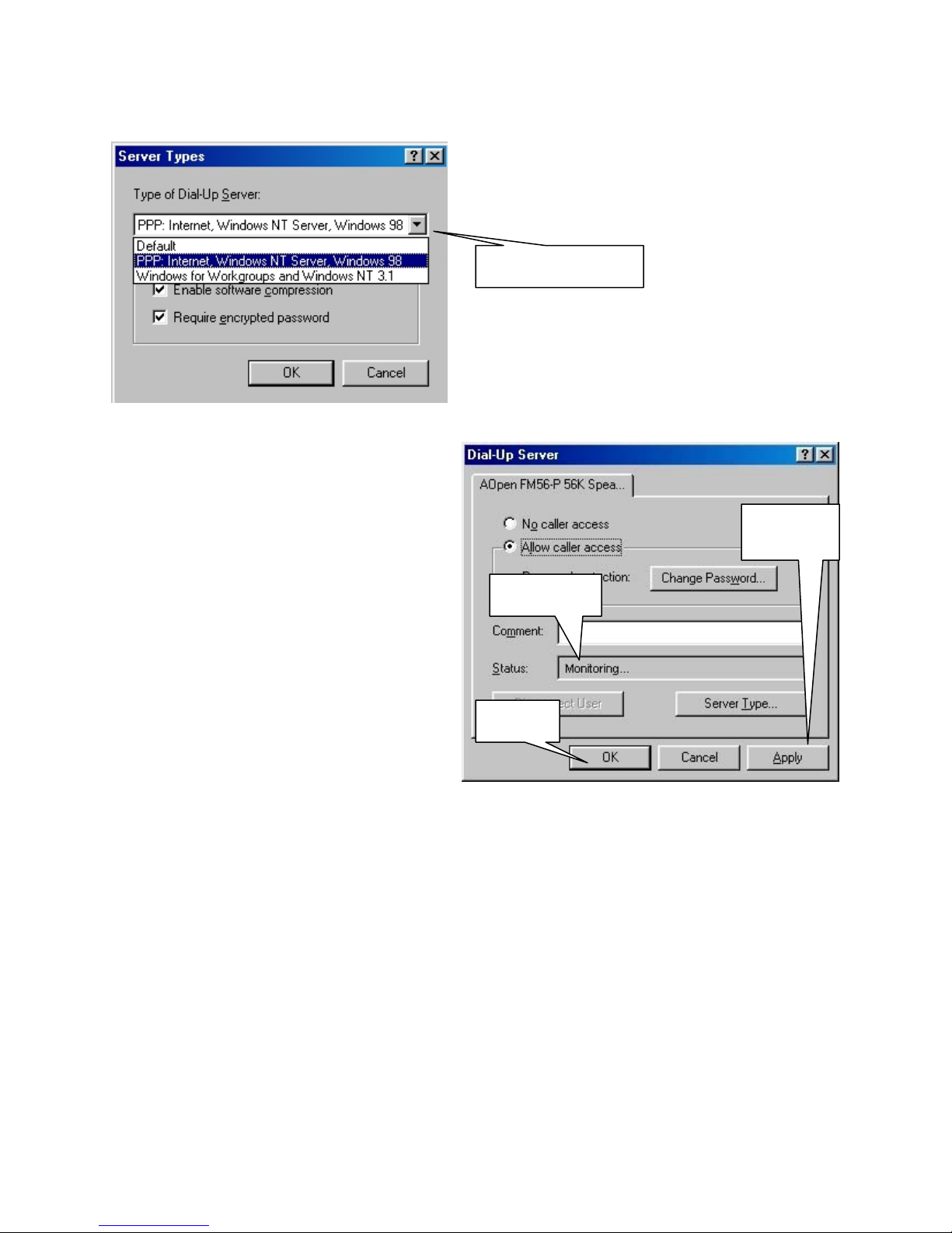
When the ‘Server Types’ dialogue appears,
choose ‘PPP, Internet, Windows NT Server,
Windows 98’ from the drop down box.
Down-Arrow
(Click on the down-arrow at the right to drop
down the menu)
Click on ‘OK’ to save this setting.
After setting the ‘Server Type’ you will
automatically return to the ‘Dial-Up
Server’ properties box.
Click on the ‘Apply’ button.
Look in the ‘Status’ box to confirm the
modem is correctly set up to answer
incoming calls. You should see
‘Monitoring’ in the status box.
If you see ‘Idle’ in the status box, then the
modem is not set up correctly. Recheck
your settings and click on the ‘Apply’
button again until you see ‘Monitoring’.
Click on ‘OK’ to finish.
Close out of all open windows by Clicking on ‘OK’, or in the case of ‘Windows Explorer’
Click on the ‘X’ button at the top right hand corner of the window to close it. If the DVR
software is not running, double-click on the ‘Electronics Line Site’ icon on the desktop to
restart it.
If you changed the modem password to something other than 1234, enter Setup mode, click
on the ‘Modem Setup’ page, and enter the new password in the ‘Pas sword’ and ‘Confirm’
boxes. Then click on the ‘Save’ button.
Your DVR is now ready to accept incoming calls from the ‘Center’ computer.
Status
OK
Apply
40
Page 41
Site Information
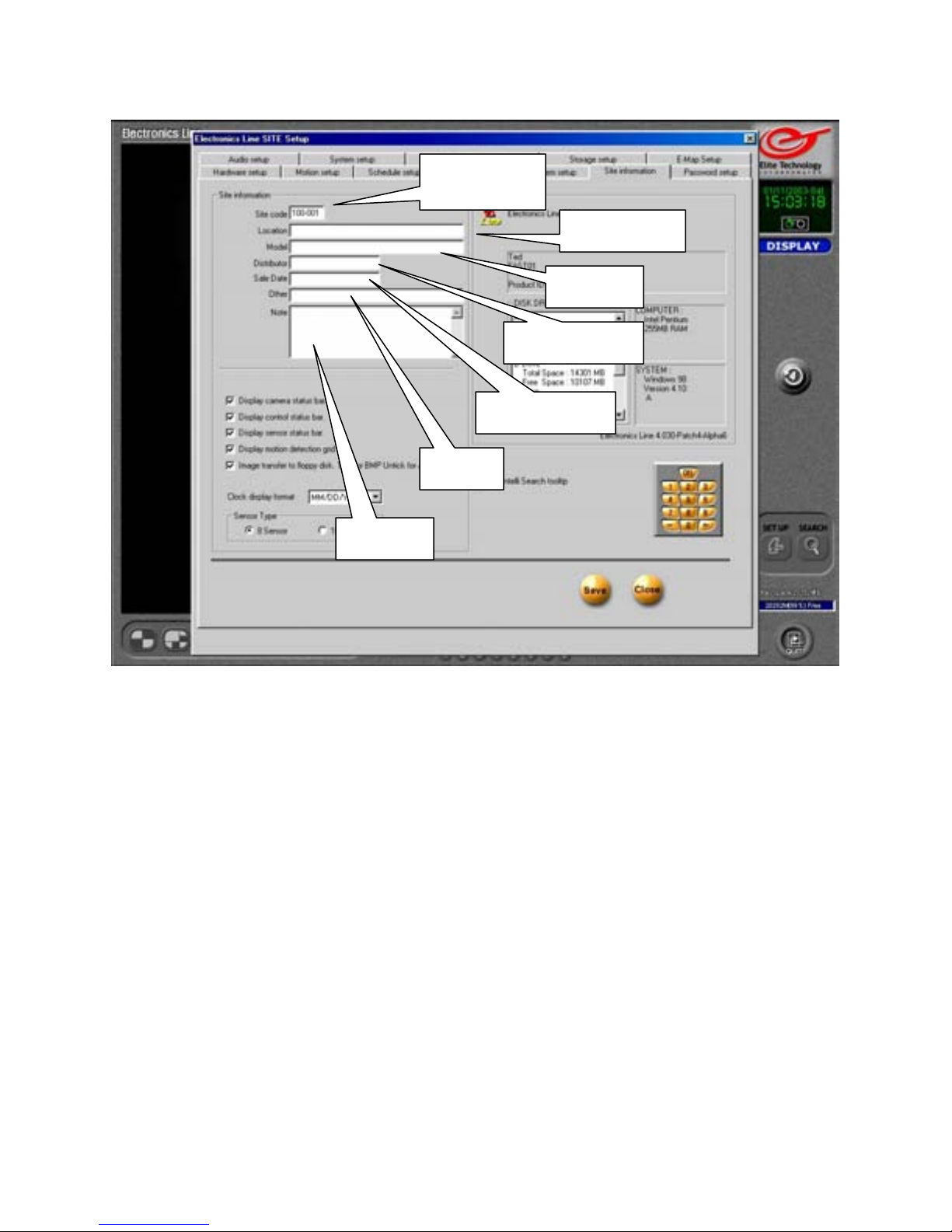
Site Code
Distributor
Sales Date
Other
Notes
Site Code
This is the Site Code you will need to enter in the Connection setup box on the remote or
‘Center’ computer when you connect to the DVR by modem or LAN.
You may rename the Site Code to any 7 digit alphanumeric name. (7 characters, using
letters, numbers, or combination of each)
If you have more than one DVR you will wish to monitor remotely, you must use a different
Site Code for each.
(Example): DVR # 1= 100-001 DVR # 2= 100-002 DVR #3= 100-003
or DVR # 1=elusa01 DVR # 2= store-2 DVR # 3= dvrmain
Location/Model/Distributor/Sales Date/Other/Notes
These are optional information entries.
You may fill in these boxes with information relating to your DVR for easy reference.
These entries will be viewable from the remote or ‘Center’ computer when you connect and
enter the setup mode.
Location
Model
41
Page 42
Site Information
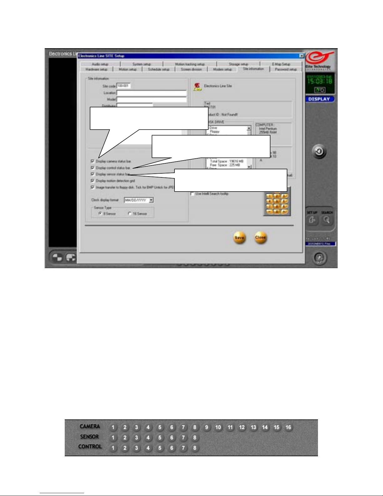
Display Camera Status Bar
Display Control Status Bar
Display Camera Status Bar
Enables the camera status indicators on the main screen. The numbered buttons will flash
when the cameras detect motion.
Display Control Status Bar
Enables the control relay status indicators on the main screen. The numbered buttons will
flash when the control relays are activated. You may also activate a control relay manually
by clicking on its associated button.
Display Sensor Status Bar
Enables the Sensor status indicators on the main screen. The numbered buttons will flash
when the sensors are activated.
Place a check in the box next to each option to enable it on the main screen. The status bars
will appear in the area below the live cameras on the main view screen.
Display Sensor Status Bar
42
Page 43
Site Information
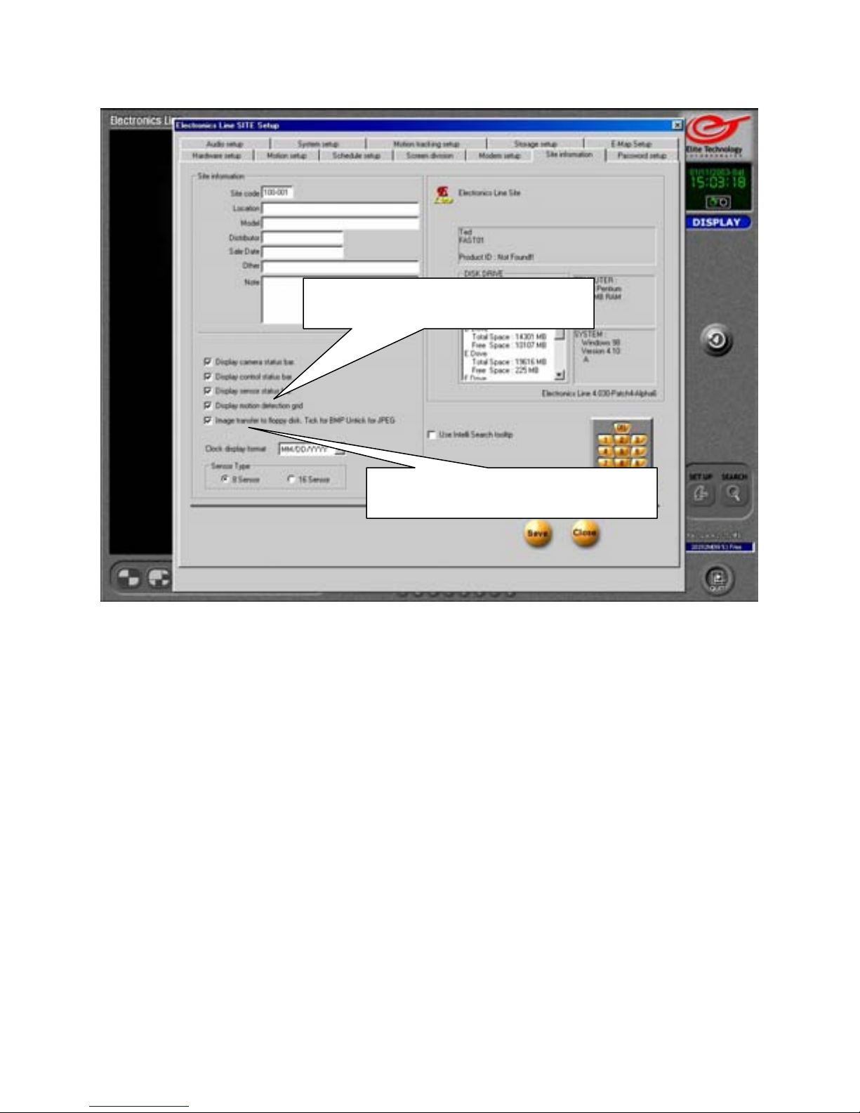
Display Motion Detection Grid
Image Transfer to Floppy Disk
Display Motion Detection Grid
If the motion detection grid is set to ‘Area Draw’ (Grid covers entire image) in the Motion
Setup section, a thin outline will appear around the outer edge of the live picture when
motion is detected by a camera.
If you selected ‘Area Clear’ and used the custom masking options by “drawing” in several
smaller motion detection grids, then a thin outline will appear around the grid that is
detecting motion within the picture. You may select the color of the outlines (red or green)
in the Motion Setup section.
(The outlines will not appear in the recorded images.)
Image Transfer to Floppy Disk
From ‘Search’ mode you can save a single still image to a floppy disk. Place a check in the
box if you wish to save the image as a Windows Bitmap file (.bmp)
Remove the check to save images in the JPEG format.
Bitmap images are better quality, but result in a larger file size on the disk.
JPEG images are lower quality, but you can save more images on a single floppy disk.
(Bitmap is the default image format.)
43
Page 44
Site Information
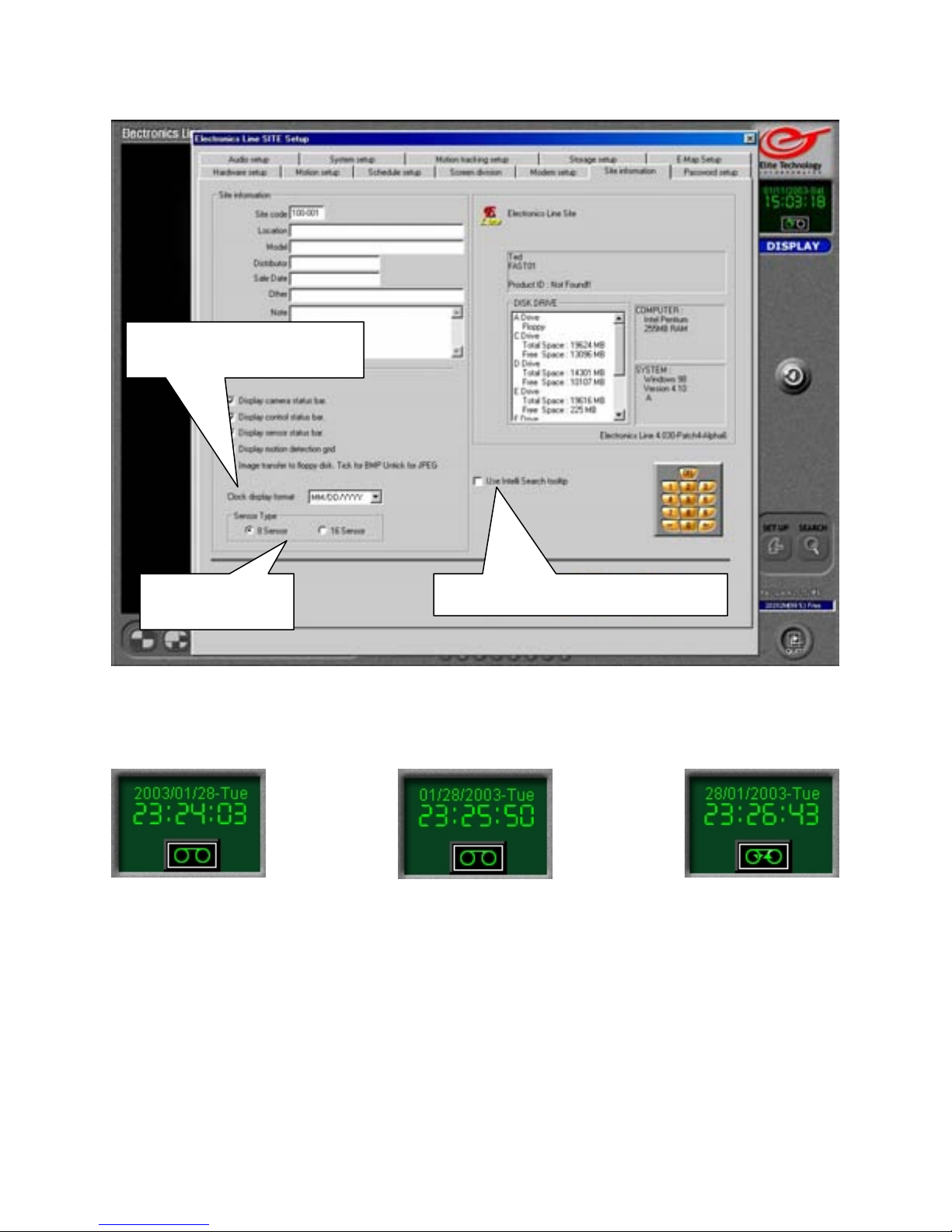
Clock Display Format
Sensor Type Use Intelli Search Tooltip
Clock Display Format
Determines how your clock will display the current date.
YYYY/DD/MM MM/DD/YYYY DD/MM/YYYY
Sensor Type
Select whether your DVR uses 8 or 16 sensors.
Use Intelli Search Tooltip
Place a check in the box if you wish to see “Pop-Up” descriptions of the buttons in Search
mode when you move the mouse cursor over them. This can be very useful if you have not
used the Search interface before.
44
Page 45
Site Information
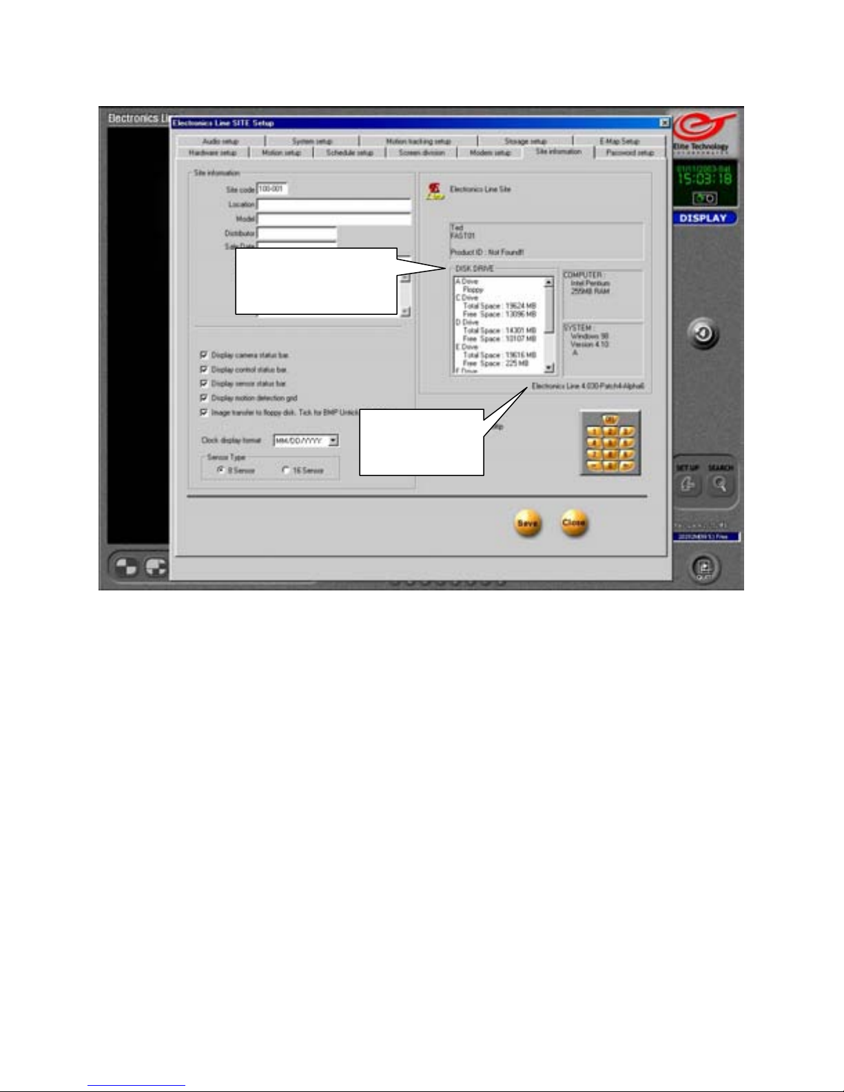
System Information
The system information area provides you with detailed information about the DVR’s
hardware including processor type, RAM (Random Access Memory) size in Megabytes,
and the Windows operating system version in use.
The ‘Disk Drive’ window shows all installed disk drives on the DVR.
A: The 3 ½ inch Floppy Drive
C: The Operating System Drive
D: The DVR Storage Drive
E: The CD-Rewritable Drive
Note: If you DVR has extra Hard Drives installed, the CD-RW drive may have a different
‘Drive Letter’ assigned to it.
Adding one extra hard drive will push the CD-RW back to F:
( The extra hard drive becomes E: )
Adding two extra hard drives will push the CD-RW back to G:
( The second extra hard drive becomes F: )
Software Version
Shows the currently installed Electronics Line DVR software version.
System
Information
Software
Version
45
Page 46
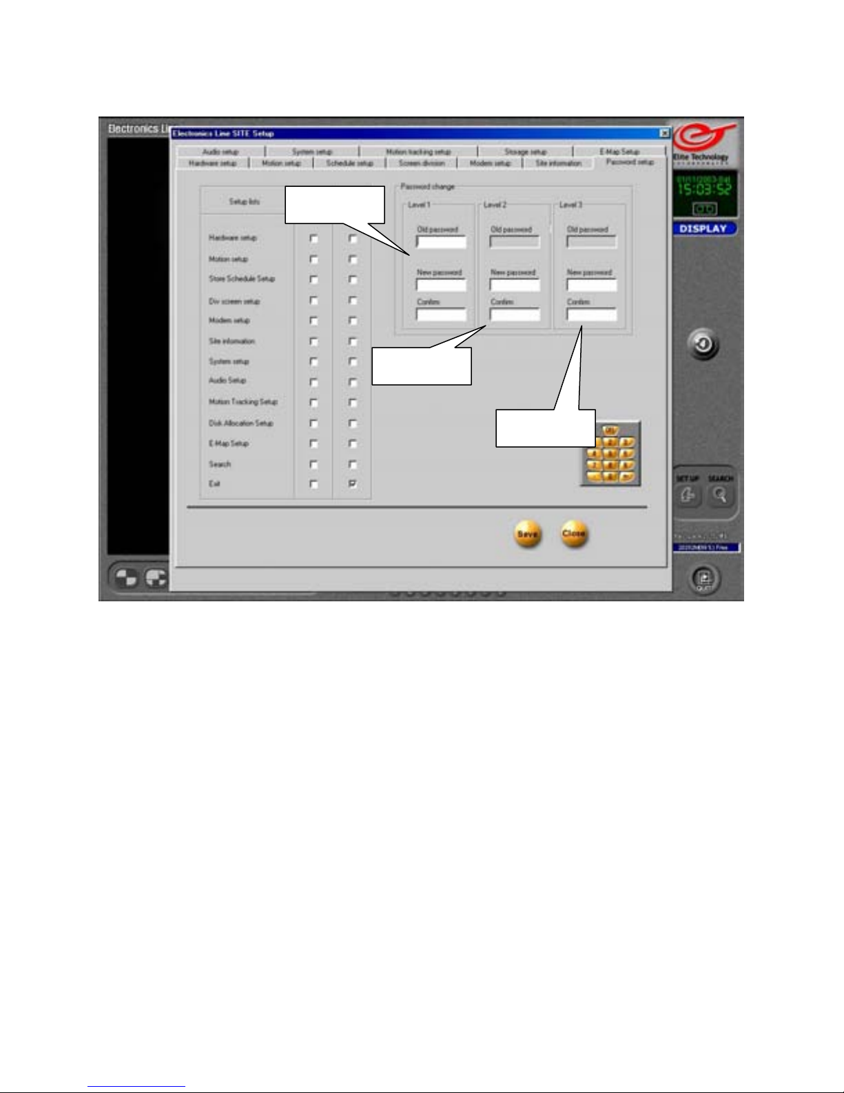
Password Setup
Level 1
The Password Setup page allows you to set or change the password for the DVR.
You are prompted for this password whenever you enter ‘Setup’ or ‘Search’ modes, or
attempt to shut the DVR software off.
This is not the password you use for Remote Access, that password is setup in
the ‘Modem Setup’ page.
Level 1 (Administrator)
To set the Level 1 password, you must enter setup as Level 1 (Administrator).
Level 1 user has access to all functions of the DVR as well as the ability to set other user
rights and restrictions. (Level 2 and Level 3 users)
Level 2 / Level 3
Level 2 and Level 3 user accounts allow you to assign certain abilities, such as ‘Search’ or
‘Site Information’ access to other users while limiting their access to more sensitive areas,
such as ‘Hardware Setup’ or ‘Storage Setup’.
Level 2
Level 3
46
Page 47
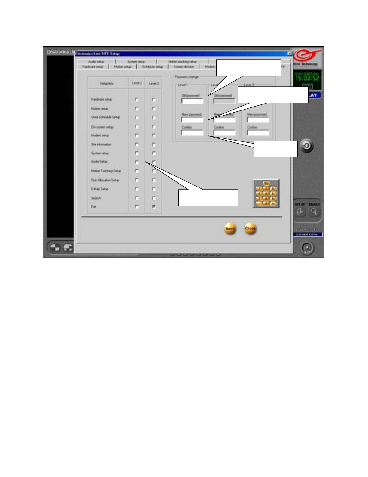
Password Setup
Setup Lists
Old Password
To change the Level 1 password, enter the password you used to enter ‘Setup Mode’
If you pressed ‘Enter’ on the keyboard or clicked on ‘OK’ to enter Setup with no
password, then leave this box blank.
Level 1 user may also change Level 2 and 3 user passwords without knowing their old
password.
Level 2 and 3 users may only change their own passwords. (If they know the old password)
New Password
Enter the new password. The password must be 4-digit numeric. (4 digits, all numbers)
Confirm
Re-enter the password to confirm it is typed in correctly.
Setup Lists
Place a check in the box for each function you wish to allow access to for Level 2 and Level
3 users. You may check as many functions as you wish in any combination. (Note that
checking all functions allows administrator level access.) Level 1 user (Administrator) has
access to all functions by default.
Old Password
New Password
Confirm
47
Page 48
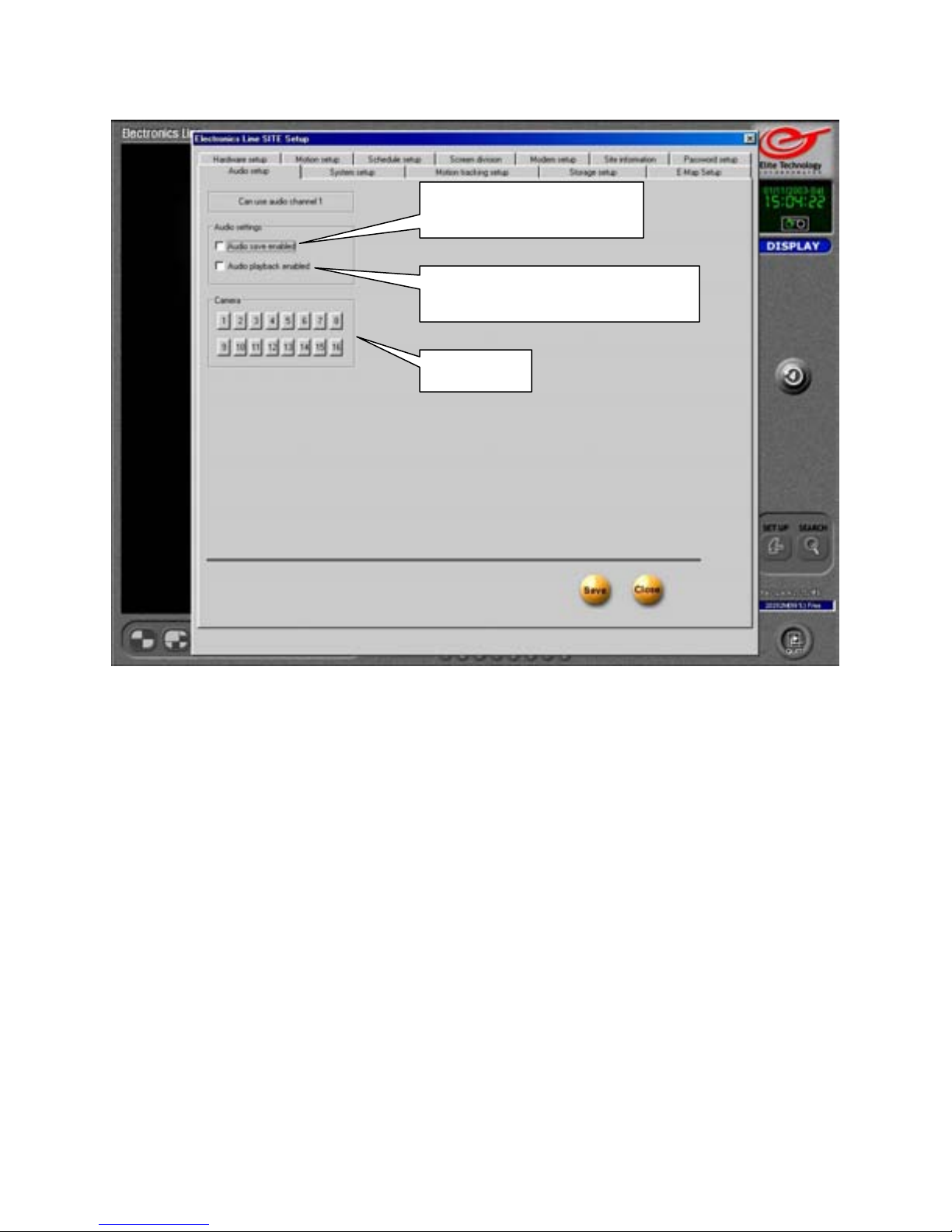
Audio Setup
Audio Save Enabled
Audio Playback Enabled
Camera
If you want to record and save audio (sound) data along with the recorded image data you
can select a camera to trigger the audio recording function. The DVR will only save audio
data when motion is detected. In order to avoid ‘choppy’ sounding playback, you should
set the associated camera to record for at least 1 or 2 seconds when motion is detected. This
is done on the ‘Hardware Setup’ page by selecting the time (in seconds) in the ‘Recording
Time by Sensor, Motion’ box.
Audio Save Enabled
Place a check in the box to enable the DVR to record audio.
Audio Playback Enabled
Place a check in the box to enable the DVR to play back audio data in ‘Search’ mode.
Camera
Click on the camera button you wish to associate to the “Audio Save’ function. Audio
(sound) will be recorded when the selected camera detects motion.
Be aware that audio recording is restricted by law in some states.
Check with your local law enforcement authorities for details.
48
Page 49
Audio Setup
Microphone and Speaker Setup
If you plan to use audio features on the DVR you will need a microphone and a set of
amplified computer speakers.
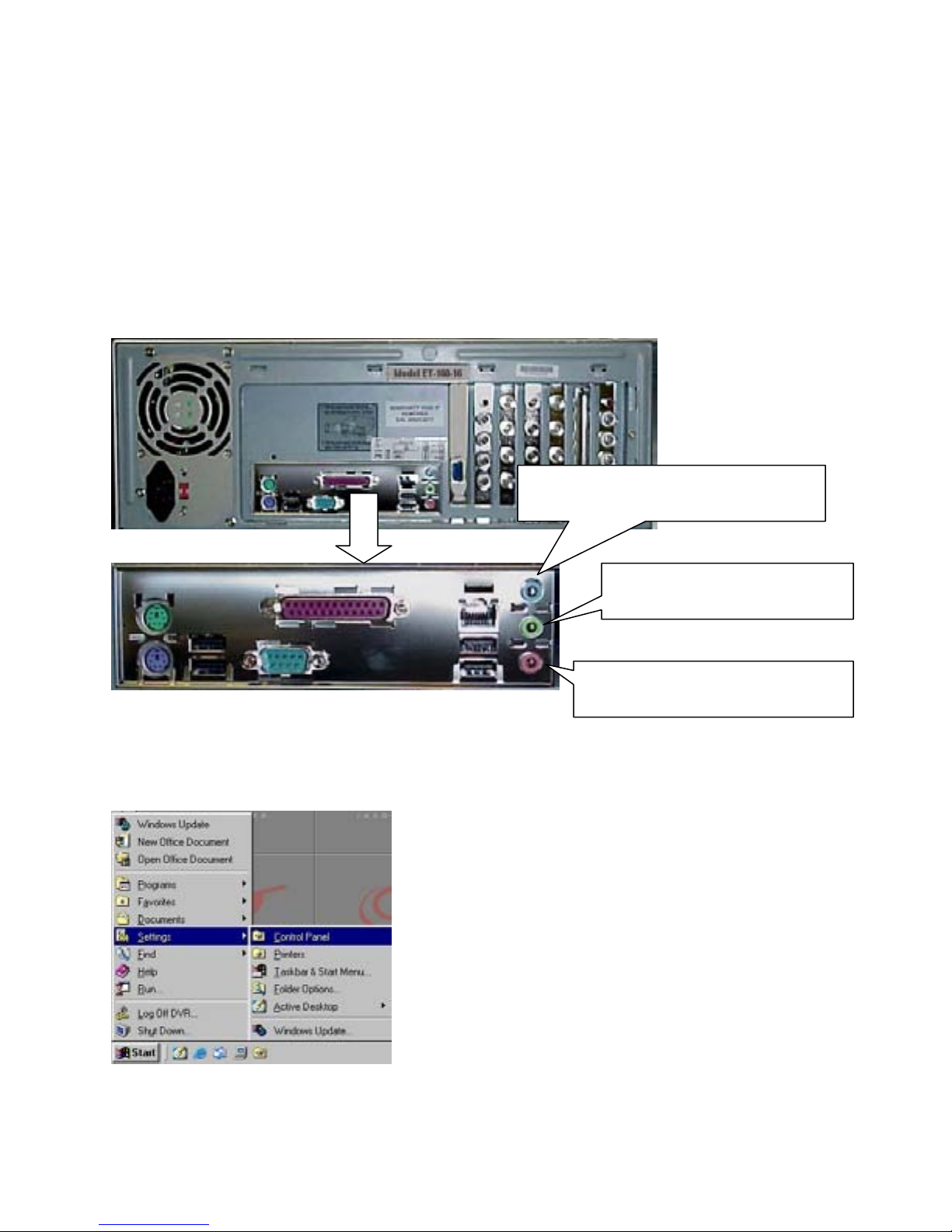
The microphone input on the back panel of the DVR is a ‘1/8 inch’ phone jack.
The microphone input usually has a PINK collar.
The speaker output on the back panel of the DVR is a ‘1/8 inch stereo’ phone jack.
The speaker output usually has a GREEN collar.
(The line input usually has a BLUE collar and is NOT USED)
If you use an amplified or powered microphone, you will still use the PINK microphone
input and adjust your volume levels down.
Back Panel of DVR
(Blue) Line input (Not used)
Once you have your microphone and speakers connected, you will need to adjust your
record and playback volumes. This is done through the Windows ‘Control Panel’.
Press the ‘Windows” key on your keyboard (between
‘Alt’ and ‘Ctrl’ on the lower left) to bring up the Start
Menu.
Use the arrows on the keyboard or use the mouse to
select ‘Settings’ and then ‘Control Panel’.
Click on ‘Control Panel’ or highlight it with the arrow
keys and press ‘Enter’ on the keyboard to bring up
the ‘Windows’ Control Panel
(Green) Speaker Output
(Pink) Microphone input
49
Page 50
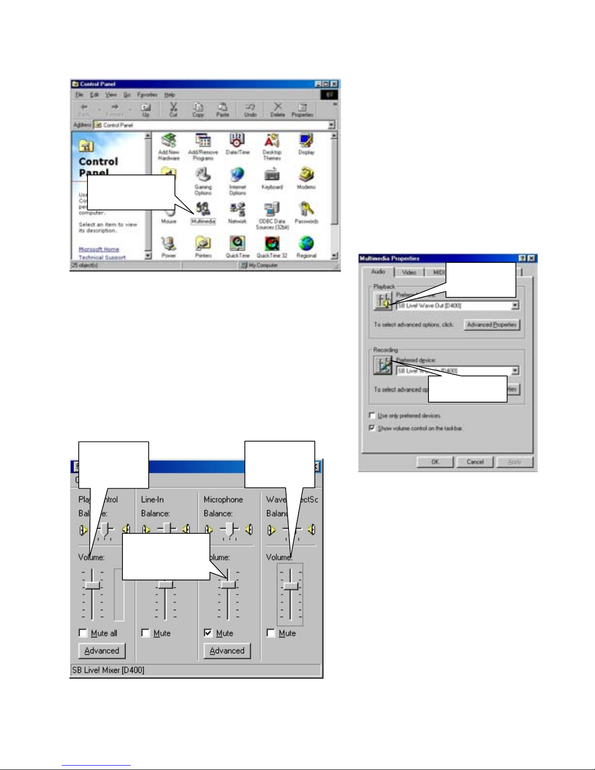
Multimedia
Audio Setup
When the Control Panel appears,
double click on the ‘Multimedia’
icon.
When the Multimedia Properties box appears
You can adjust the volumes and other properties for
both the Record and Playback devices by clicking on
the icons on the left side of the box.
Click on the Playback button to adjust your output
volumes first.
Main
Volume
Wave
Volume
Microphone
Volume
Playback
Recording
Main Volume
Use the sliders to set the Main Volume
to around ¾ up.
Microphone Volume
Set the Microphone volume to the
same range.
Wave Volume
Set the Wave volume to the same
range.
50
Page 51
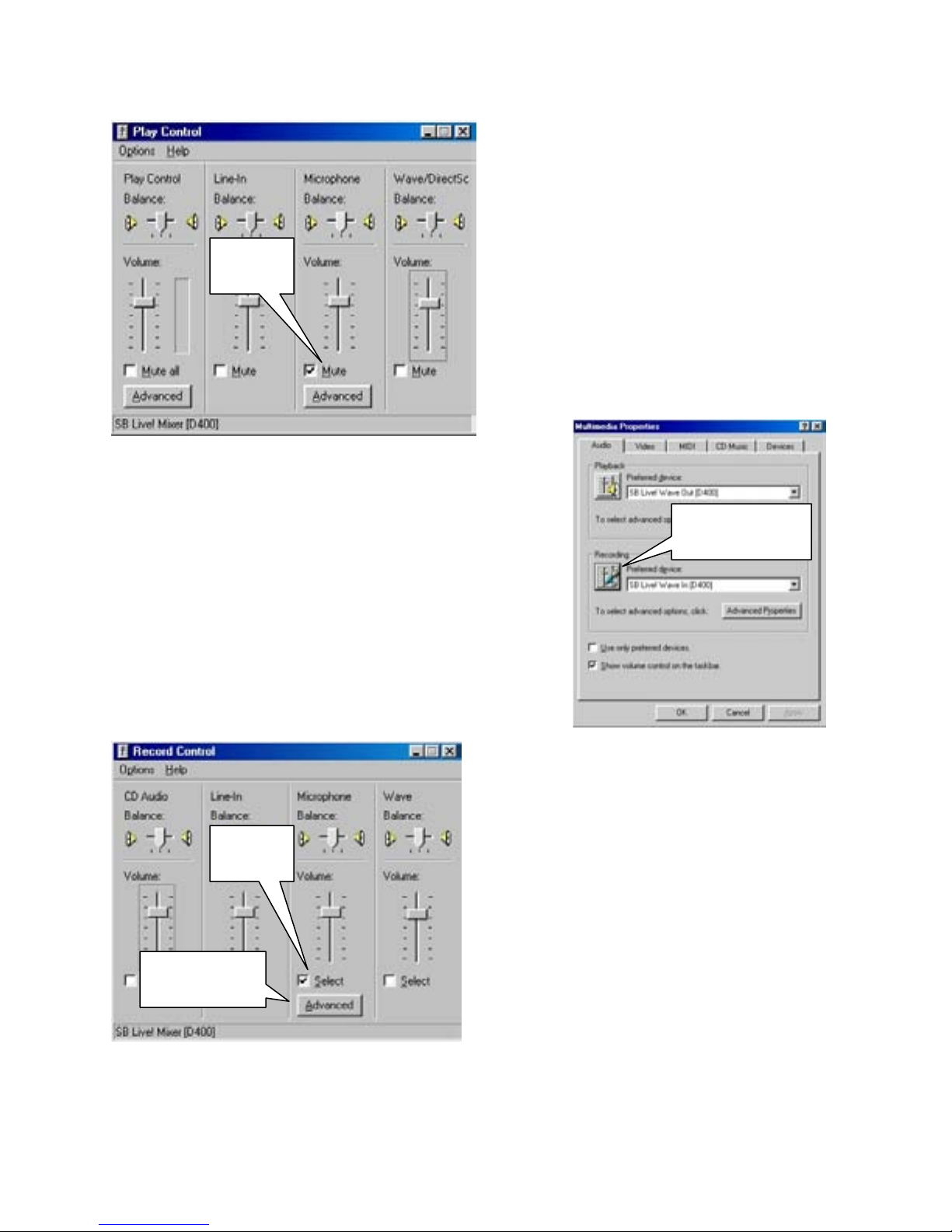
Audio Setup
Mute
Place a check in the ‘Mute’ box if you do
not want the ‘Live” audio from the
microphone to play through the speakers.
(Especially if you want to listen to recorded
Mute
If the Live volume is too high or too low,
Return to the ‘Multimedia Properties’ box and click on
the ‘Recording” button.
This will bring up the ‘Record Control’ box.
Select
Advanced
audio in Search mode.)
The Recorded audio will still playback in
Search mode.
Uncheck the ‘Mute’ box to test the
microphone volume level.
Select
Place a check in the box to select the
microphone as the recording device.
Then adjust the volume slider until you can
hear the audio clearly.
Advanced
If you move the volume slider all the way up
but you still can not hear the audio clearly,
move the volume slider to the bottom, and
click the ‘Advanced’ button.
Recording
51
Page 52
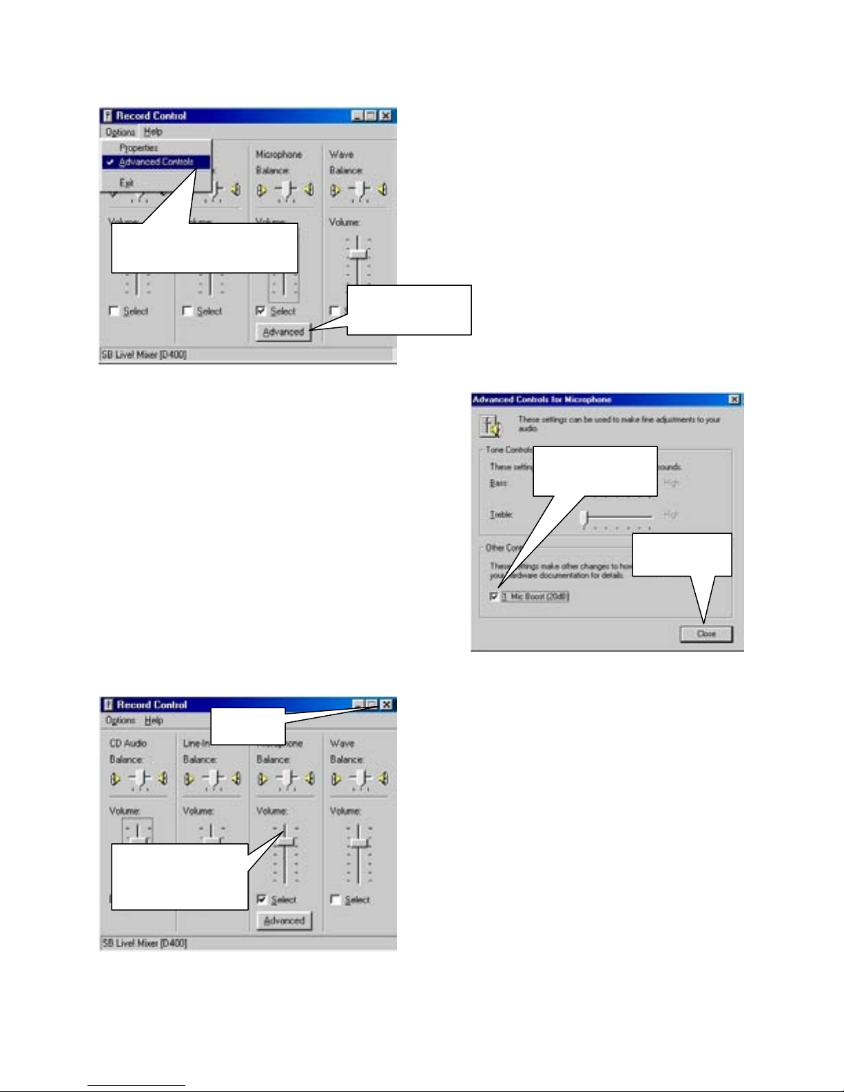
Audio setup
If you do not see an ‘Advanced’ button, click
on ‘Options’ and choose ‘Advanced Controls’
from the drop-down menu.
Advanced Controls
Advanced
Place a check in the ‘Mic Boost (20dB)’ box and
click on ‘Close’ to exit.
This will increase the input sensitivity of the
microphone.
Close
Microphone
volume
52
Then click on the ‘Advanced’ button that
appears under the Microphone volume slider.
Now move the slider up until you can hear the
audio signal clearly. Try not to set the level too
high to avoid distortion or clipping of the audio
data and possible damage to the sound card.
When the sound is set to the desired level, use
the ‘X’ button in the upper right corner to
close the Record Control box.
Mic Boost
Close
Page 53
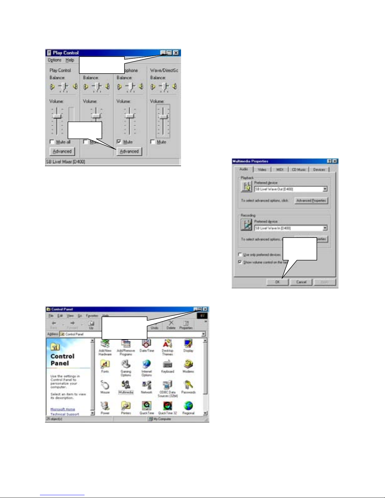
Audio Setup
Close
Mute
Click on ‘OK’ to close the ‘Multimedia Properties” box.
Close
Once you have the volume controls set to the
desired level, place a check in the ‘Mute’ box to
stop the Live audio from playing through the
speakers.( The audio will still be recorded and
will playback normally.)
Then click on the ‘X’ button at the top right to
close the ‘Play Control’ box.
Click on the ‘X’ button in the upper
right corner to close the ‘Control
Panel’.
Your DVR is now ready to record and
playback audio data.
Remember to select the ‘Audio Save
Enabled’ and ‘Audio Playback
Enabled’ options on the ‘Audio Setup’
page.
OK
53
Page 54
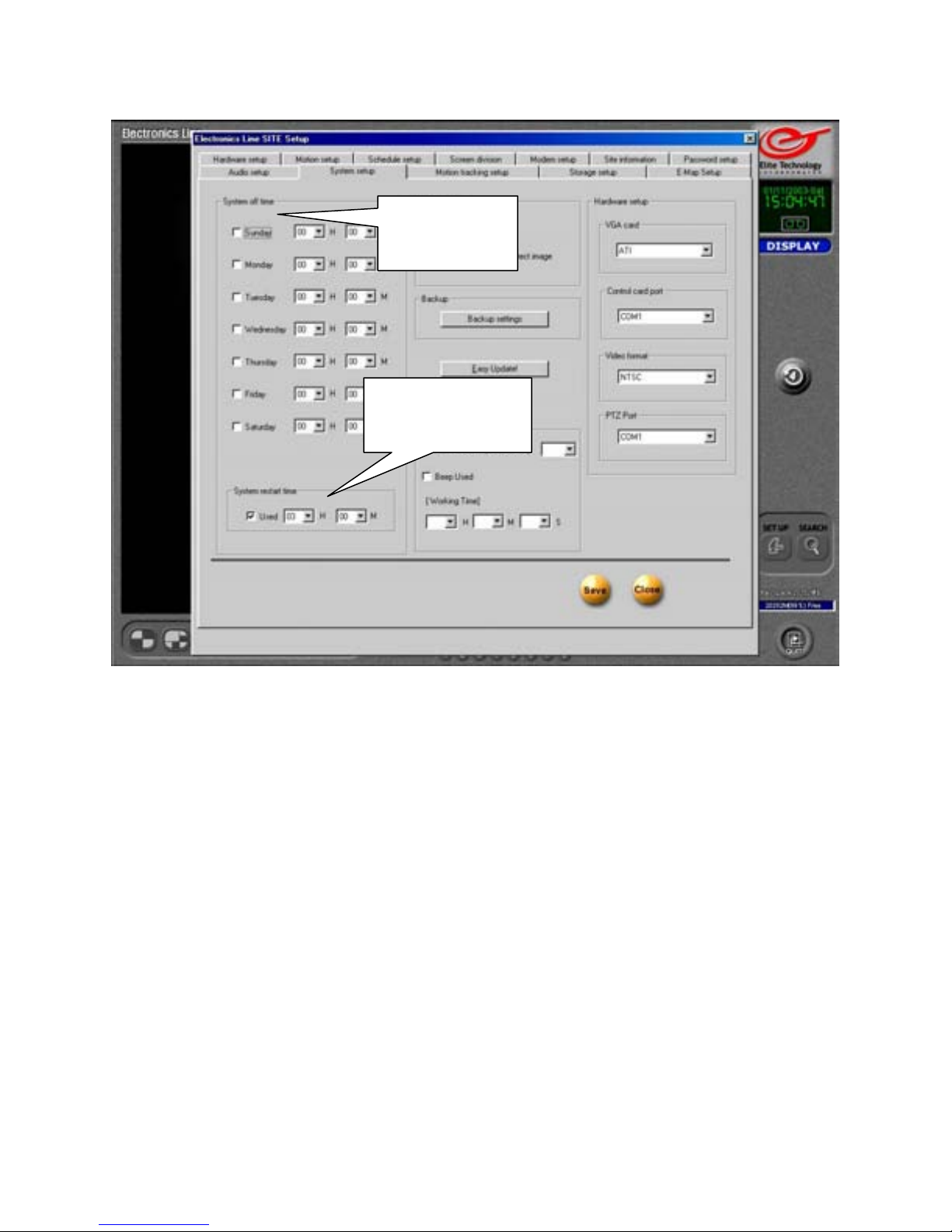
System Setup
System Off Time
Place a check in the box next to the day(s) you want the DVR to turn itself off. Set the off
time in the Hour and Minute boxes. (Use the 24 Hour time format.)
Be aware that this is a complete shutdown, NOT a restart time. Your DVR
will remain OFF until you use the ‘Power” button on the front of the DVR to
turn it on again.
System Restart Time
Place a check in the box to enable the DVR to ‘reboot’ itself at the specified time every day.
Enter the restart time in the ‘Hour’ and ‘Minute’ boxes. (Use the 24 Hour time format.)
The default restart time is 3:00 am
Example: To have the DVR reboot at 11:00pm, enter 23 ~ 00
54
System Off
Time
System Restart
Time
Page 55
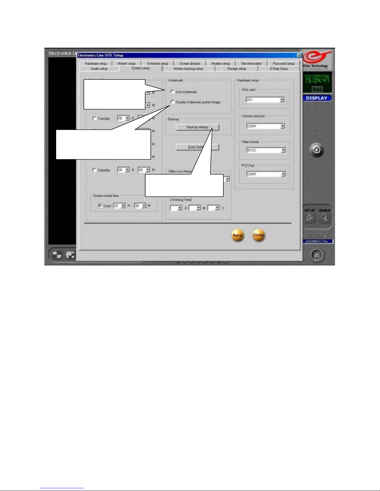
System Setup
Display Watermark
Protect Image
Use Watermark
Place a check in the box to enable the DVR to use an embedded watermark when you
record an image. The watermark is a digitally encoded algorithm placed into the image file
to verify the integrity of the image.
If the image is altered in any way, the watermark verification will fail.
A watermarked image is usable as evidence in a court of law because it can not be
tampered with.
Display Watermark Protect Image
Place a check in the box to display the word ‘Watermarked’ on the protected image.
Refer to the ‘Still Image Backup’ section of ‘Search Mode’ later in this manual for more
information on the ‘Watermark’ function.
Backup Settings
The Backup panel allows you to set a scheduled backup of stored image data to another
data drive. You can backup to an internal or external hard drive, a formatted recordable
CD, a removable device such as a “ZIP” drive, or to a remote location on a computer
running the ‘Electronics Line Center Remote Backup Server’.
Click on the ‘Backup Settings’ button to open the system backup panel.
Use
Watermark
Backup Settings
55
Page 56
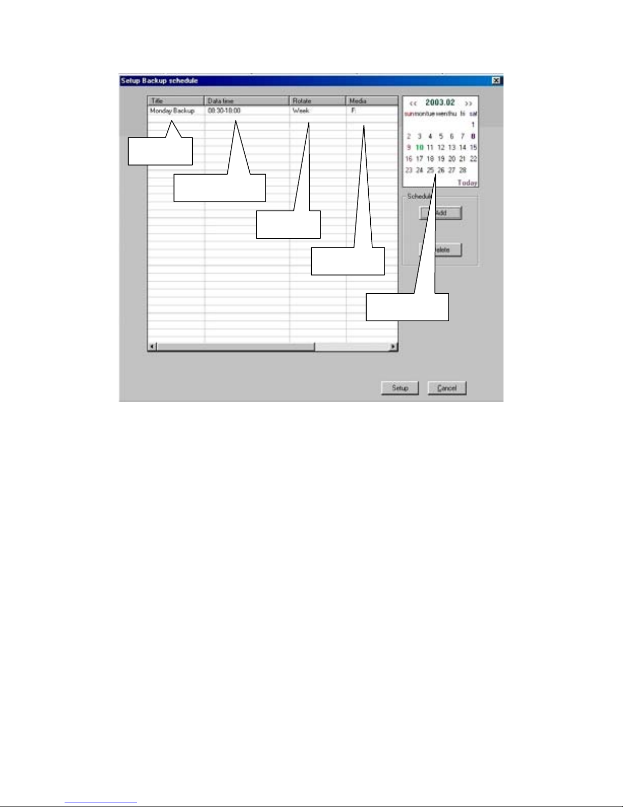
System Setup
Title
Data Time
Rotate
System Backup Panel
Title
When you select a day on the calendar (by left clicking on it) any backup scheduled for that
day will appear in the information area. The ‘Title’ column will show the name you enter
when you create a backup.
Data Time
The interval of time that will be backed up. (Displayed in 24-hur format)
(Example: Time to be backed up in picture above is from 8:30am until 6:00pm).
Rotate
Week, Month, Year, or None will indicate how often this backup is set to repeat.
Media
The hard drive, removable drive, or remote drive letter that this backup will be saved to.
Calendar
Use the calendar to see if you have a backup scheduled for a particular day. Click on any
day to select it. The Calendar shows the currently selected day in Green. Any backup(s)
scheduled for the selected day will appear in the information area.
56
Media
Calendar
Page 57
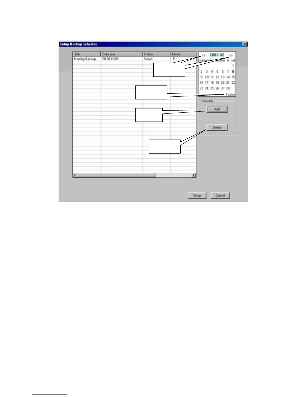
System Setup
Today
Add
System Backup Panel
Arrows
Click on the arrows to change the month displayed on the calendar.
Click << to go back a month. Click >> to go forward a month.
Today
Click on ‘Today’ at any time to return to the current month and day.
Add
Click on the ‘Add’ button to create a new backup schedule. The ‘Add Schedule’ panel will
appear. This is where you will create a new backup schedule.
Delete
To remove a scheduled backup, left-click on the backup listing in the information area and
click on the ‘Delete” button. This will remove the scheduled backup from the list. This will
NOT delete any backup files that were created by the schedule.
Arrows Arrows
Delete
57
Page 58
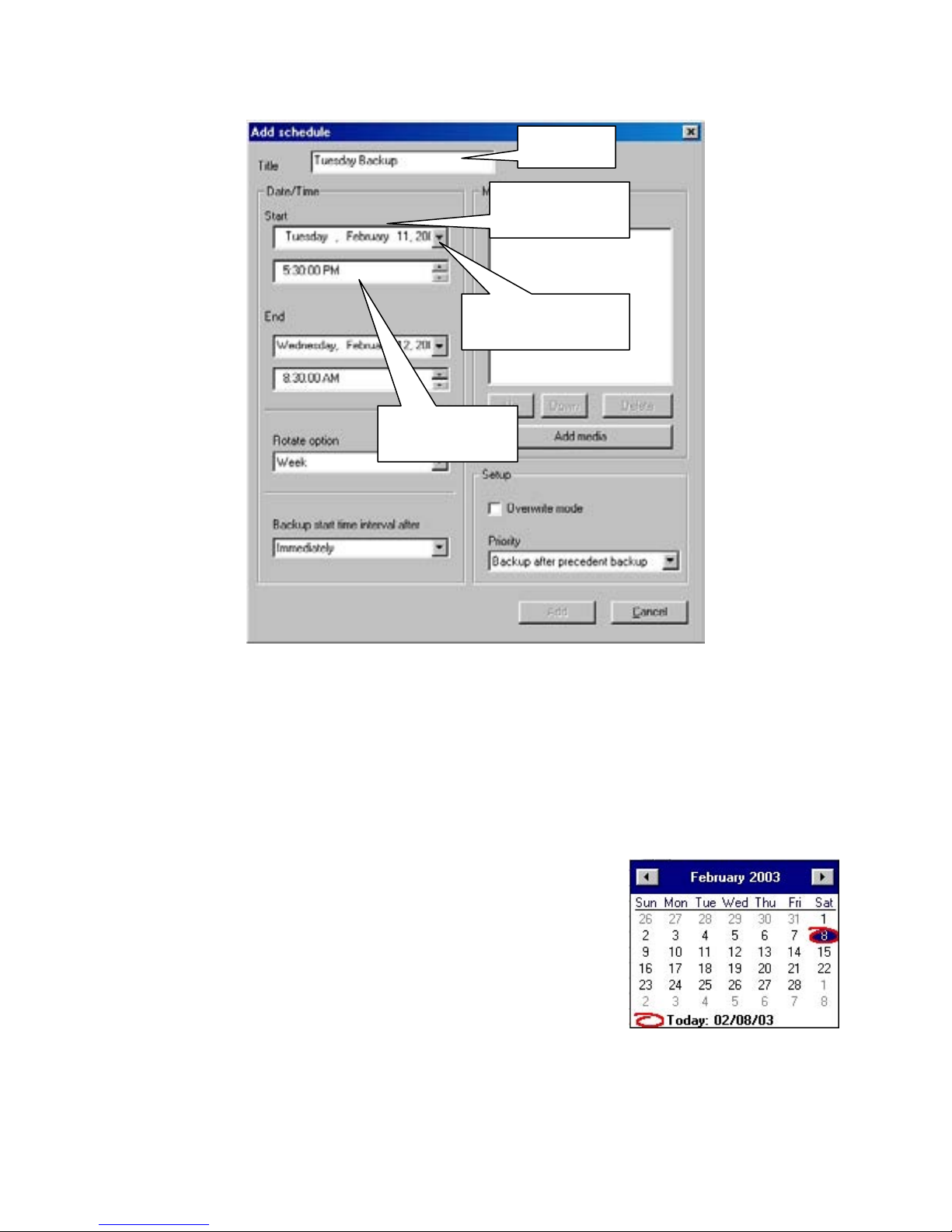
System Setup
Start Time
Down Arrow
Add Schedule
When you click on the ‘Add’ button in the System Backup Panel, the ‘Add Schedule’
dialogue will appear.
Title
Enter a unique name for your backup. You can use numbers, letters, or combination of
both.
Start Date
Click on the ‘Down Arrow’ to open the calendar. Use the left
and right arrows to select the month, and then click on the day
you wish to backup.
Start Time
Enter the starting time of the period you wish to back up.
(Example: To back up an entire night of data from 5:30pm
until 8:30am the next morning, enter 5:30 PM in the Start Time box.)
Title
Start Date
58
Page 59
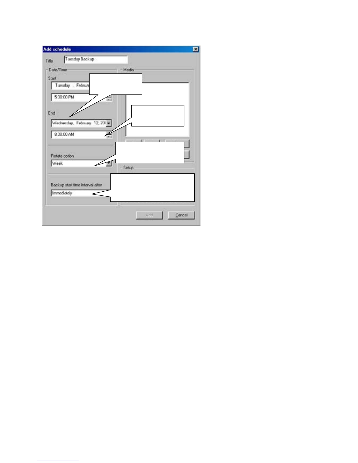
System Setup
End Date
End Date
End Time
Rotate Option
Backup Start Time
Interval After
Rotate Option
Use the Rotate Option to cause your backup to repeat automatically. Back up the same
period of time every week, month, or year. If a Rotate Option is used, the dates are treated
differently according to the option chosen.
Example
:
Start Time “Tuesday, February 11, 2003at 5:30 PM”
End Time “Wednesday, February 12, 2003 at 8:30 AM”
In this example, if you choose the Rotate Option:
Week:
up. The numeric date, month, and year are ignored.
Month:
backed up. The day of the week (Tuesday, Wednesday), month, and year are ignored.
Year:
(Tuesday, Wednesday), and year are ignored.
None:
Every Wednesday morning at 8:30am, the previous 15 hours of data will be backed
On the 12th day of every month at 8:30am, the previous 15 hours of data will be
Every year on the 12th of February the data will be backed up. The day of the week
The selected backup will occur only one time, on the selected date and time.
Backup Start Time Interval After
You may have the backup begin Immediately after the ‘End Time’ has passed, or you may
choose to delay the backup for up to 4 hours after the ‘End Time’ has passed.
Set the end date for the data you
wish to back up.
(Example: To back up a night of
data from 5:30pm until 8:30am the
next morning, select the day that
follows the ‘Start Date’.)
End Time
Enter the end time of the data you
wish to back up.
(Example: To back up a night of
data from 5:30pm until 8:30am,
enter 8:30 AM in the End Time
box.)
The back up will automatically
start when the End Time has
passed.
59
Page 60
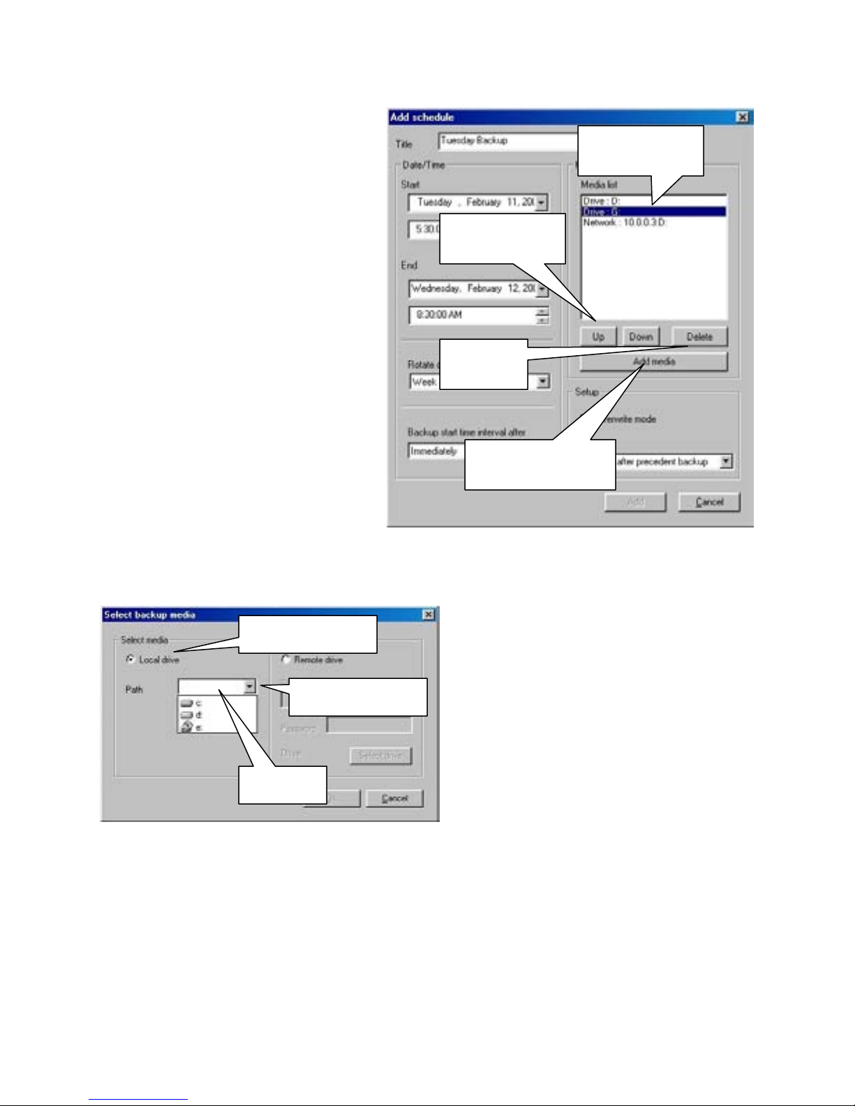
System Setup
Media List
Any drives used for backup will
appear in the Media List.
Up / Down
Set the priority of the available
backup drives. The DVR will default
to the first drive in the list. To move a
drive up or down on the list, click on
the drive to select it and click on the
Up or Down buttons to move it.
Up / Down
Delete
Delete
Click on a drive to select it and click
on the Delete button to remove it
from the Media List. (This will not
delete any data on the drive.)
Add Media
Add Media
If there are no drives listed in the
Media List, then you will need to add
at least one for the DVR to backup to.
Click on the ‘Add Media’ button to select a backup drive.
Local Drive
The ‘Select Backup Media’ panel will
appear.
Down Arrow
Path
Local Drive
You may select a drive that is physically
installed on the DVR. This can be an
internal or external hard drive, mapped
network drive, “ZIP” or other removable
drive, or a formatted CD-R / CD-RW
disk.
Path
Click on the ‘Down Arrow’ to show the available drives installed on the DVR. Click on a
drive to select it as the backup drive.
Do NOT select the ‘C’ drive or any drives that are allocated for data storage
by the DVR for backup. Backing up to the ‘C’ drive or allocated storage
drives will interfere with the operation of the DVR.
Media List
60
Page 61
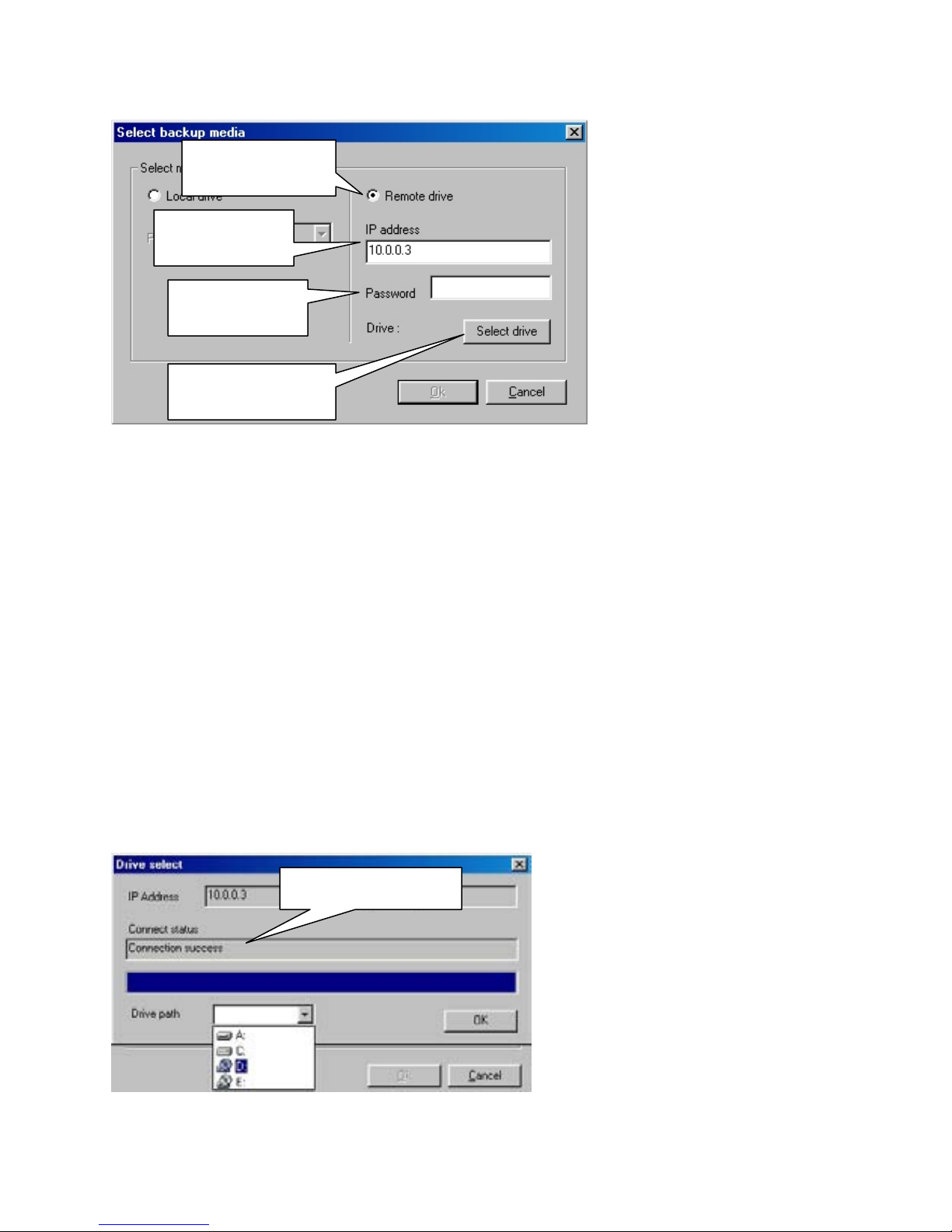
System Setup
Remote Drive
IP Address
Password
Select Drive
Note:
drive path as an installed drive. The ‘Remote Drive’ path can connect to any computer via
the LAN (Local Area Network) or the WAN (Wide Area Network) including the Internet if
the backup computer has a Network, DSL, or Cable Modem connection with a fixed, or
‘Static’ IP address.
A network drive mapped through “Windows” networking will appear in the ‘Local’
IP Address
Enter the ‘Internet Protocol’ address of the remote computer you wish to backup your data
to. (The remote computer must have the K-Remote Backup Server software running or the
connection will fail.)
Password
Enter the password (if any) that you have set up in the K-Remote Backup Server software.
Select Drive
When you have entered the IP address and password of the remote computer, click on the
‘Select Drive’ button to connect.
The Drive Select panel will open to
Connect Status
show your connection status. If the
connection was successful, the
‘Connect Status’ box will show
‘Connection success’. If the IP
address is not correct, or the KRemote Backup Server is not
running on the remote computer,
the ‘Connect Status’ box will read,
‘Connection Fail’.
Remote Drive
You may select a remote, or
network drive to backup to.
The remote computer
must have the
‘Electronics Line Center’
software installed and
the ‘K-Remote Backup
Server’ running
.
61
Page 62
System Setup
Remote Drive Path
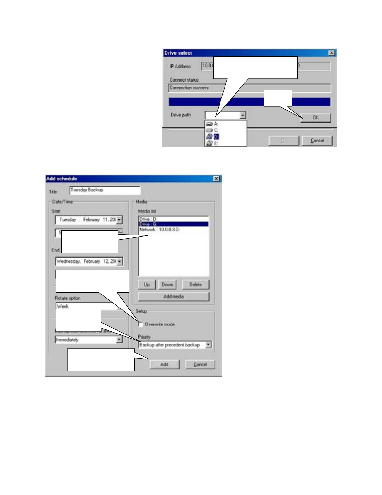
When you successfully connect to
the remote K-Network Backup
Server, you will be able to select a
backup drive from the drop down
list. Click on the drive to select it.
The drive will appear in the ‘Drive
Path’ window.
OK
When you have selected a backup
drive, click on the ‘OK’ button to confirm your choice. The ‘Drive Select’ panel will close.
Media List
Overwrite Mode
Priority
Add / Cancel
Select ‘Backup after current backup’ if you have one backup in progress and another one
waiting, but you want this backup to complete before the one that is waiting.
Add / Cancel
Click on the ‘Add’ button to complete the backup schedule and add it to the list of
scheduled backups, or click ‘Cancel’ to stop without creating a scheduled backup.
Remote Drive Path
OK
The ‘Add Schedule’ panel will
now show the remote drive in the
‘Media List’. You can add more
drives with the ‘Add Media’
button, or click on one of the
available drives in the list to select
it as the drive for your backup.
Overwrite Mode
Place a check in the box if you
want the new backup to overwrite
(erase) the old data when the
backup drive becomes too full to
hold more data.
Priority
Set the priority of the current
backup. Select ‘Backup after
precedent backup’ if you have a
backup in progress, and another
backup waiting, and you want
this backup to wait until both
previous backups have completed.
62
Page 63
System Setup
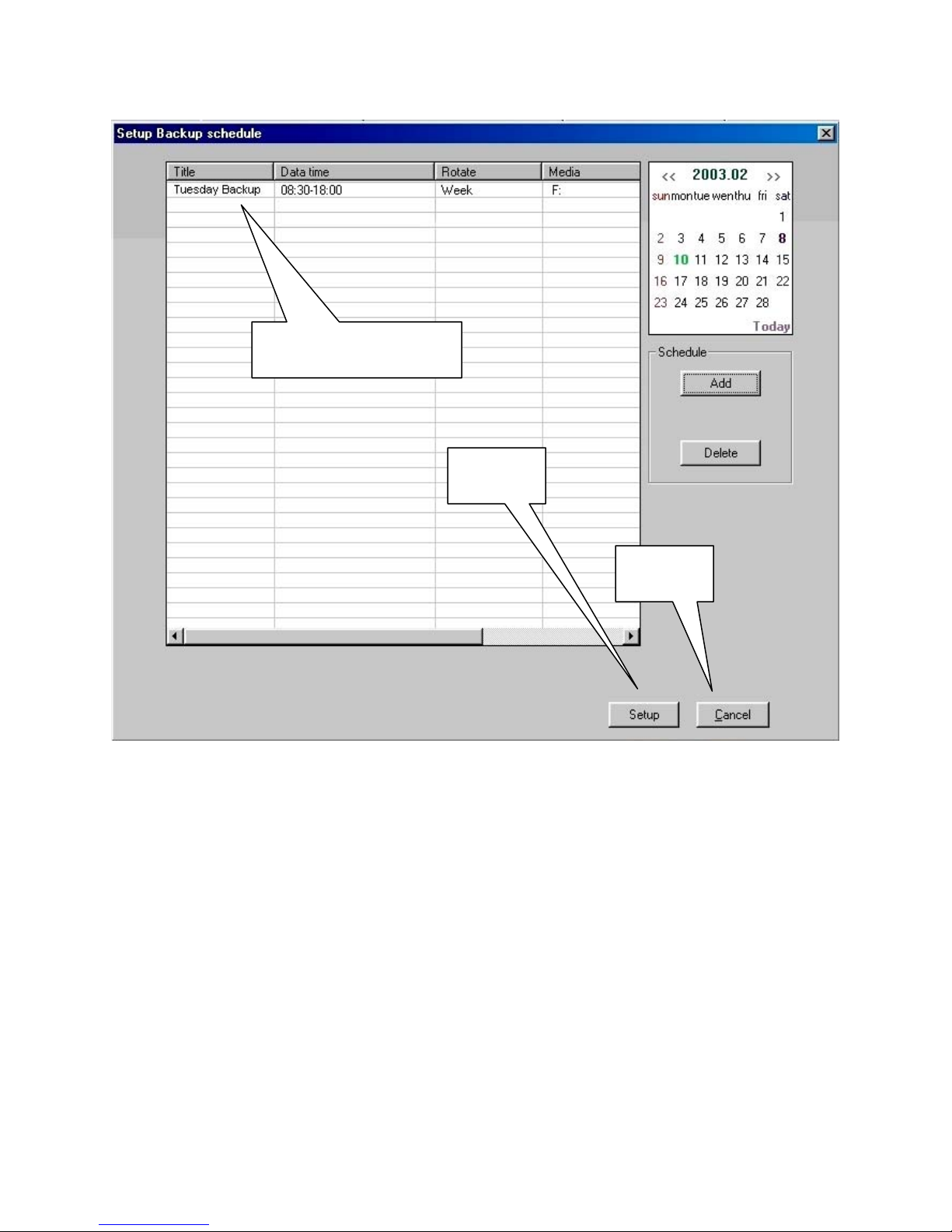
Scheduled Backup
Setup
Cancel
Scheduled Backup
Once you have completed setting up your backup, it will appear in the System Backup
Panel.
Setup
Click on the ‘Setup’ button to save your backup(s) and return to ‘System Setup’.
Cancel
Click on the ‘Cancel’ button to quit without saving and return to ‘System Setup’.
Warning: If you select ‘Cancel’, any backups you created, and any changes
you made to pre-existing backups will NOT BE Saved.
63
Page 64
System Setup
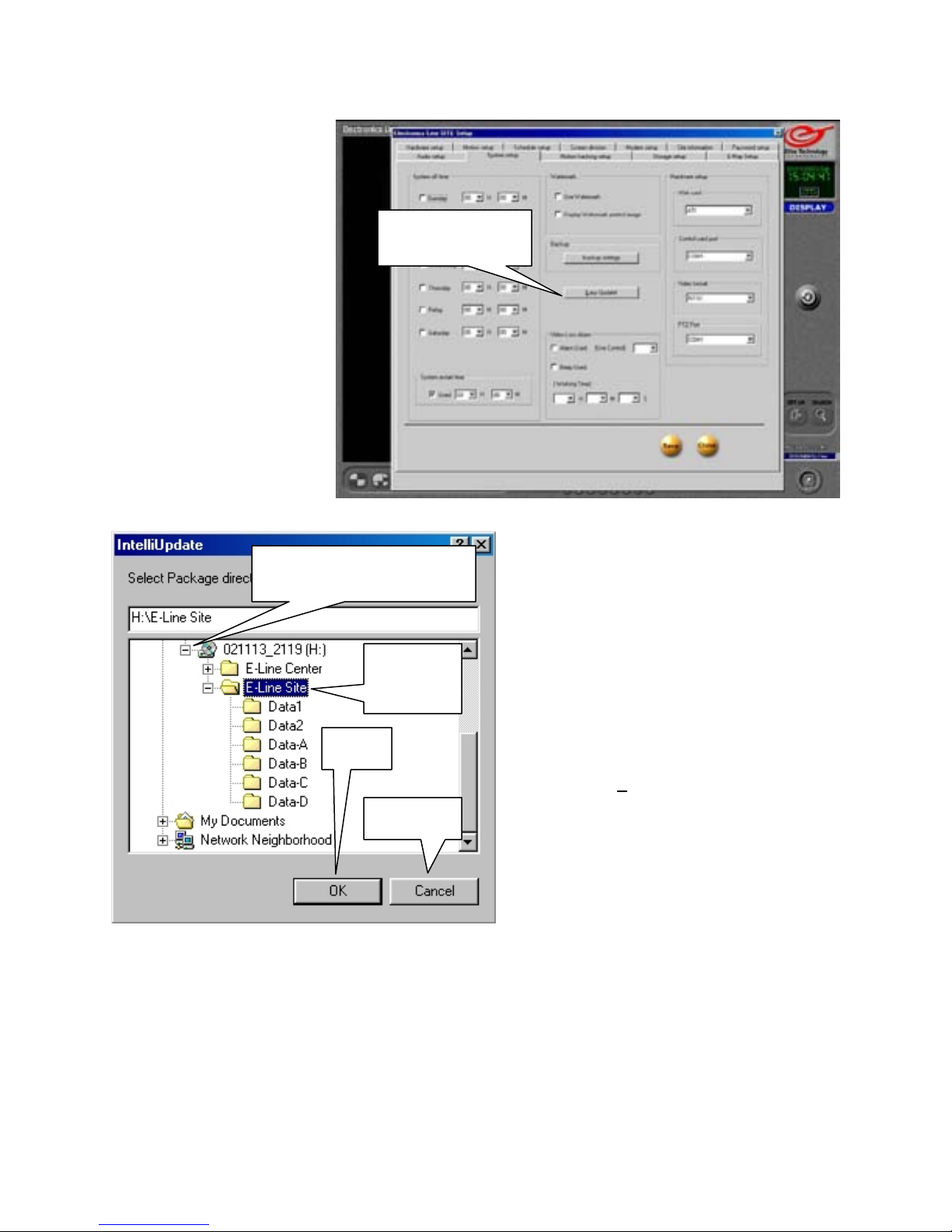
Easy Update
The easy update feature
allows you to upgrade
your DVR software to the
latest version available.
You can download the
latest updates from the
Elite Technology FTP
site, or speak with a
service representative to
obtain the latest update
on CD-ROM. Once you
have the update files
available at the DVR,
click on the ‘Easy Update’
button to begin.
Click to Open Drive
OK
OK
When you have selected the folder containing the update package, the OK button will
activate. (It remains ‘Grayed-Out’ until you select the correct folder) Click on the OK
button to begin the upgrade process.
Cancel
Click Cancel to quit and return to the DVR Main Screen without updating.
Easy Update
Select
Update
Cancel
When you click on the ‘Easy Update’
button, the ‘IntelliUpdate’ browser
window will appear.
If the update files are on a CD, place the
CD in the CD drive and wait 5 seconds
for the DVR to ‘read’ the disk.
Find the CD drive in the browser
window.
Click to Open Drive
Click on the [+
folder to open it.
] next to a drive icon or
Select Update
Find the E-Line Site folder containing
the update package and click once on it
to select it.
64
Page 65
System Setup
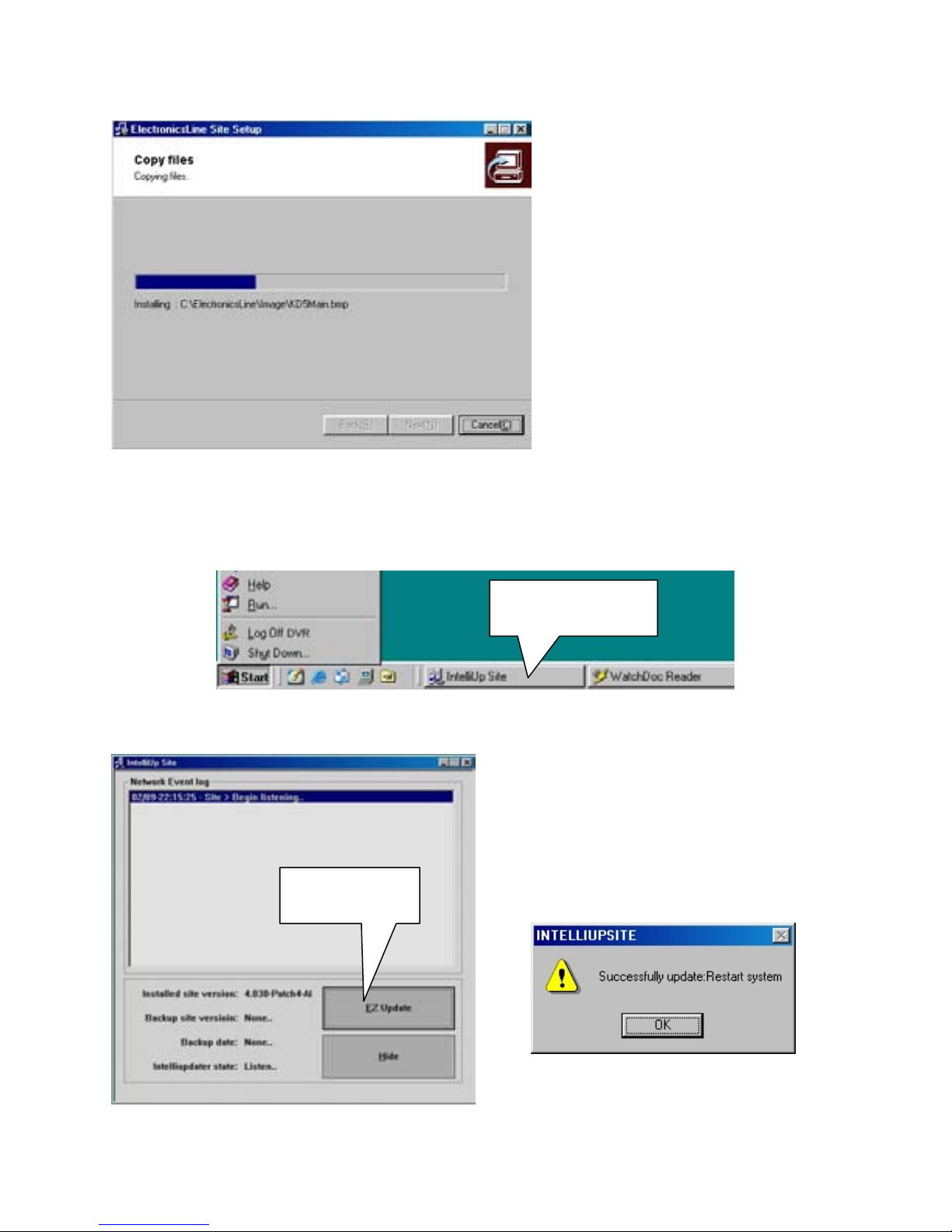
When you select the folder
containing the update package from
the ‘IntelliUpdate’ browser window,
and click on the ‘OK’ button, the
DVR will begin the update process.
The new files will be copied to the
DVR’s hard drive and installed
automatically.
When the update is installed, the
DVR will close the Electronics Line
Site software and prompt you to
reboot.
If the update fails to install, a message will appear to notify you. Click on OK to
acknowledge the error and install the update through the ‘IntelliUp Site’ panel instead.
To access the ‘IntelliUp Site’ panel, move your mouse cursor to the bottom of the monitor
or press the ‘Windows Key’ on your keyboard to bring up the Windows ‘Start’ bar.
IntelliUp Site
Click on the ‘IntelliUp Site’ button to bring up the IntelliUp Site panel
Click on the ‘EZ Update’ button to bring
up the ‘IntelliUp Site’ browser and reinstall
the update package.
EZ Update
IntelliUp Site Panel
When the update finishes installing you
must reboot the DVR.
Click the ‘OK’ button to reboot the DVR.
65
Page 66
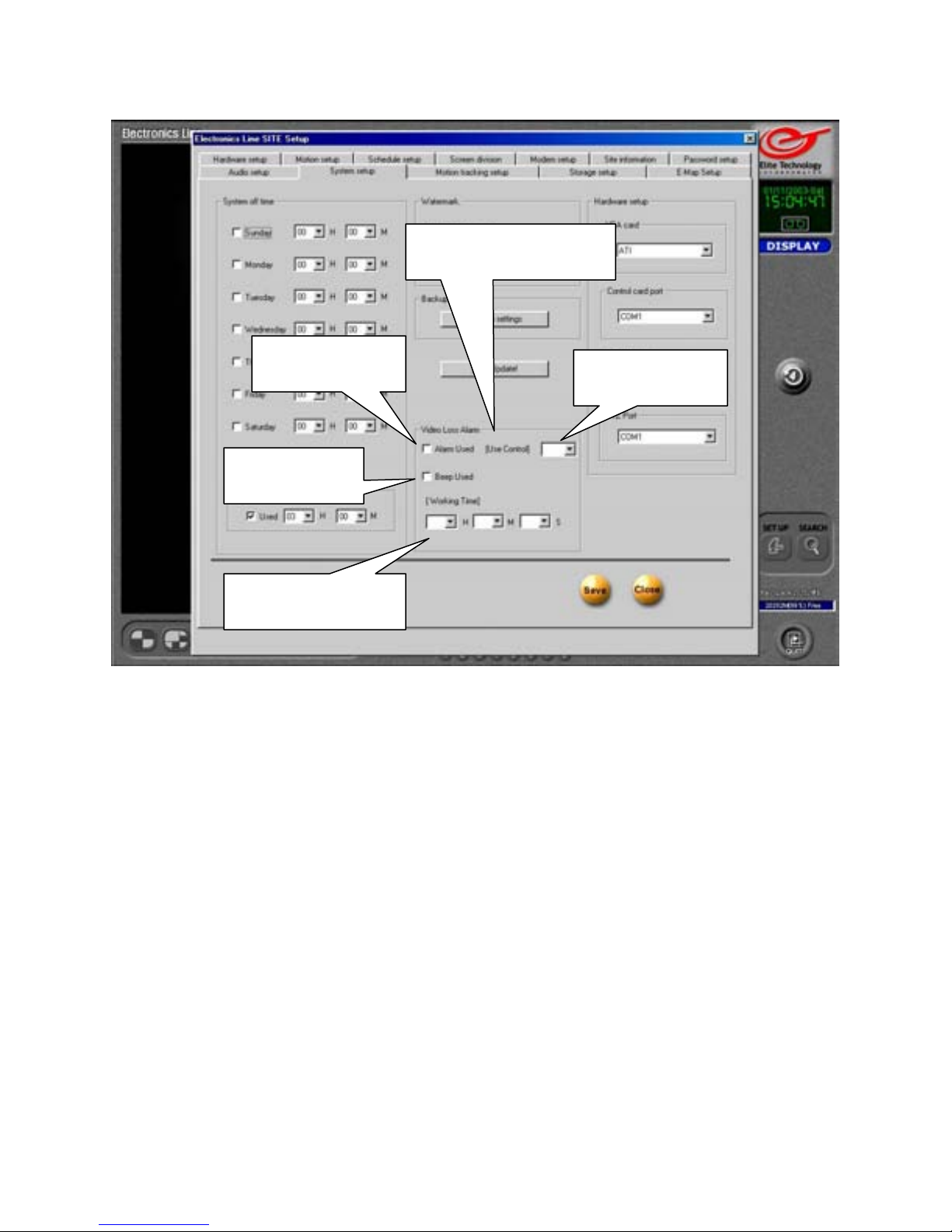
System Setup
Video Loss Alarm
Alarm Used
Beep Used
Working Time
Video Loss Alarm
You can set the DVR to trigger an alarm if video loss occurs. The alarm can be a buzzer,
siren, strobe light, or any device that can be activated by the Control Relay Outputs.
The DVR will also send an alert to the remote, or ‘Center’ computer which will appear in
the ‘Health Monitor’ window.
Alarm Used
Place a check in the ‘Alarm Used’ box to enable the function.
Use Control
Select the Control Relay you want to use when video loss occurs. The control can activate
an external alarm, warning lamp, etc.
Beep Used
Place a check in the ‘Beep Used’ box to have the DVR emit a tone from its internal speaker
on video loss.
Working Time
Set how long you want the alarm to continue after being activated. Enter the time in hours,
minutes, and / or seconds.
Use Control
66
Page 67
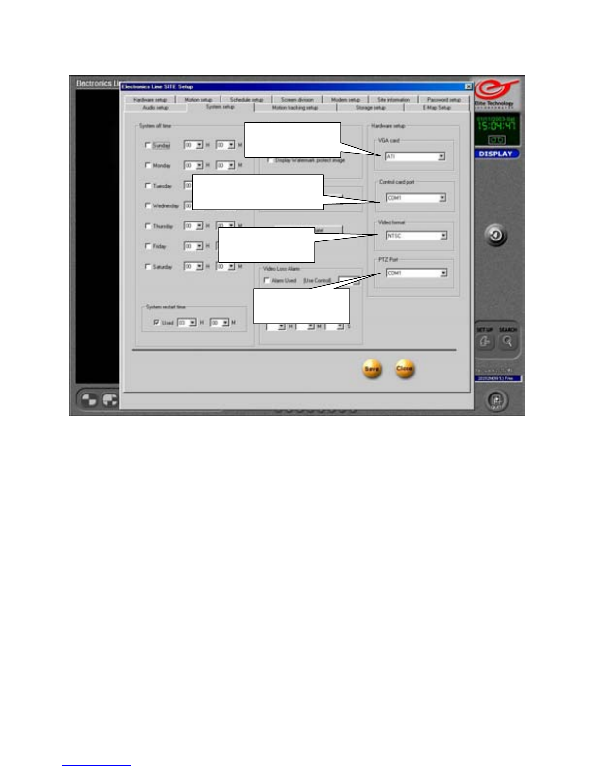
System Setup
VGA Card
Control Card Port
Video Format
PTZ Port
Hardware Setup Information
These selections are preset to the correct values.
Do not change these values unless instructed to do so by an
Electronics Line USA Support Representative.
VGA card
Identifies the installed video card chipset manufacturer.
Control Card Port
Selects the port used by P/T/Z control card.
Video Format
Selects NTSC or PAL format. Default format is NTSC.
PTZ Port
Selects which port is used for Pan Tilt Zoom camera control when no P/T/Z control
card is used.
67
Page 68
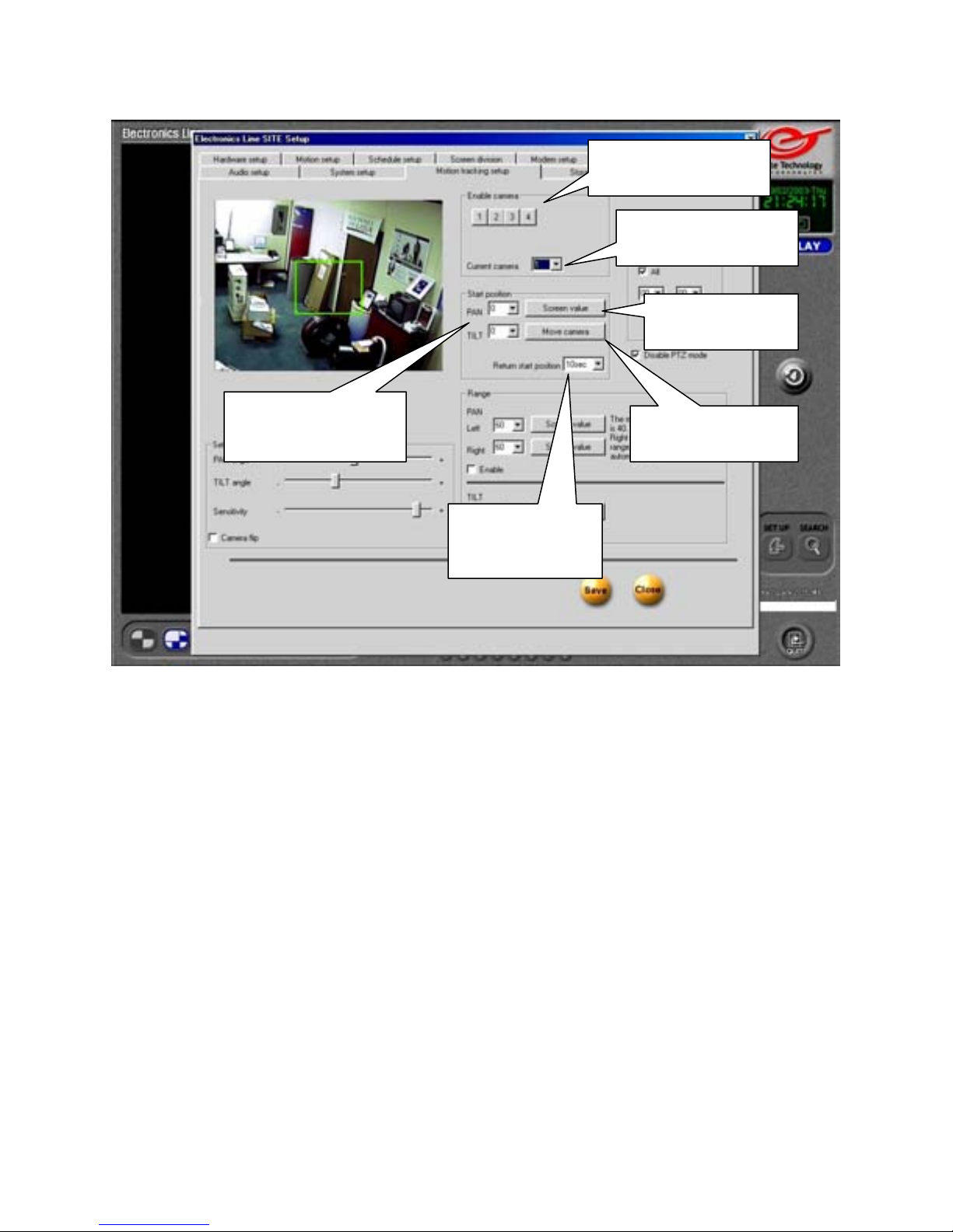
Motion Tracking Setup
Start Position
Pan / Tilt Values
Return Start
Position
Enable Camera
Click on the camera buttons to enable motion tracking function.
You must select the appropriate camera in the ‘Hardware Setup’ section before these
buttons will appear.
Current Camera
Use the drop down arrow to select the camera you want to set up. The selected camera’s
live image will appear in the area on the left.
Screen Value
Click to set the value to the position showing in the camera image.
Start Position Pan / Tilt Values
Use drop down arrows to set start position of motion tracking camera. Camera will return
to this position when motion is no longer detected and followed.
Move Camera
Click to move camera to values entered in the ‘Pan’ and ‘Tilt’ boxes under ‘Start Position”
Return Start Position
Use the drop down arrow to select how long the camera will remain in its last position afte r
motion is no longer detected and followed.
Enable Camera
Current Camera
Screen Value
Move Camera
68
Page 69
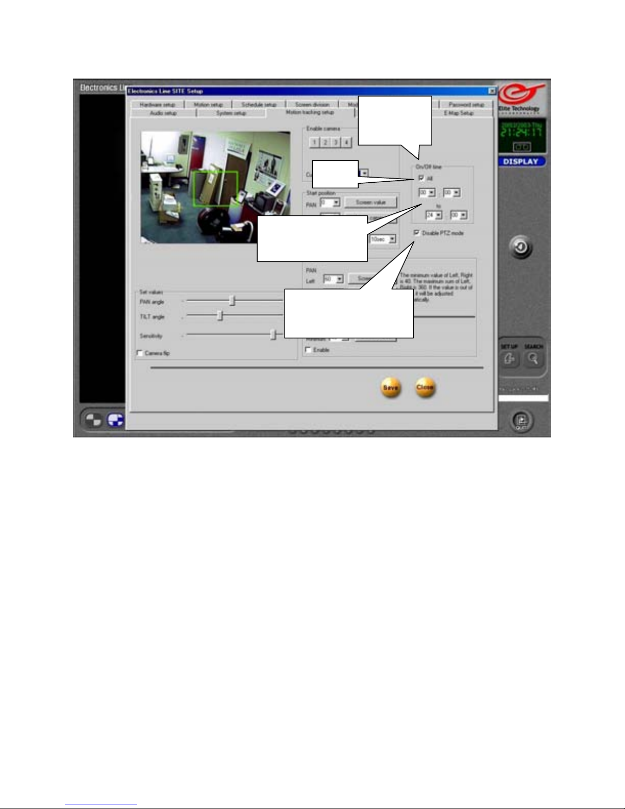
Motion Tracking Setup
All
Start / End
Times
Disable P/T/Z
Mode
On/Off Time
Set the range of time for the motion tracking function to be active.
All
Place a check in the box to set the same active time range for all motion tracking cameras.
Leave the box unchecked to set a different time range for each camera.
Start / End Times
Use the drop down arrows to set the start and end times for the motion tracking function to
be enabled. (Use 24-hour time format) Enter the start time in the upper boxes and the end
time in the lower boxes. Default is 00:00 to 24:00. (Midnight to midnight)
Disable P/T/Z Mode
Place a check in the box to disable manual Pan/Tilt/Zoom control on the selected camera.
Manual operation of a Motion Tracking camera through the P/T/Z controls will interfere
with the Motion Tracking function. The camera will not return to its configured Start
position if you manually Zoom/Focus it with the P/T/Z controls.
On / Off
Time
69
Page 70
Motion Tracking Setup
Left / Right
Enable
Tilt
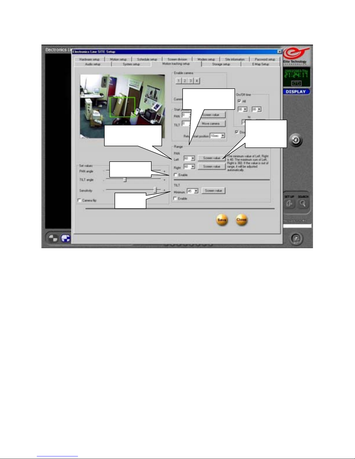
Pan Range
You can set a limit on how far the motion tracking camera will move from the start
position while following detected motion.
Left / Right
Use the drop down arrows to set the maximum range of movement of the motion tracking
camera in degrees. The minimum value you may enter for left or right angles is 40 degrees.
The total sum of both left and right angles can not exceed 360 degrees. (Full circle)
Screen Value
Click on the Screen Value button to set the Pan angle to the current camera position.
Enable
Place a check in the box to enable the Pan Range function for the selected camera.
Tilt
Use the drop down arrow to set the minimum tilt of the selected camera, or use the ‘Screen
value’ button to set value to current camera position.
Place a check in the enable box to enable minimum tilt function.
Pan Range
Screen
Value
70
Page 71
Motion Tracking Setup
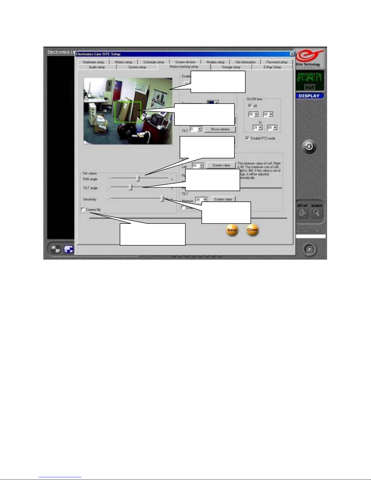
Camera Flip
Live Image
Live view of currently selected camera. Left click in the image to adjust the camera angle.
Selection Box
Target zone of motion tracking camera.
Pan angle
Use slider to fine tune selected pan values. (In Start Position and Range)
Tilt Angle
Use slider to fine tune selected tilt values. (In Start Position and Tilt)
Sensitivity
Adjust sensitivity higher in dark areas, and lower in brightly lit areas.
Camera Flip
If camera is installed in a flipped position, motion tracking may appear to work in reverse.
Place a check in the box to correct this.
Live Image
Selection Box
Pan Angle
Tilt Angle
Sensitivity
71
Page 72
Storage Setup
Modify
Storage
Structure
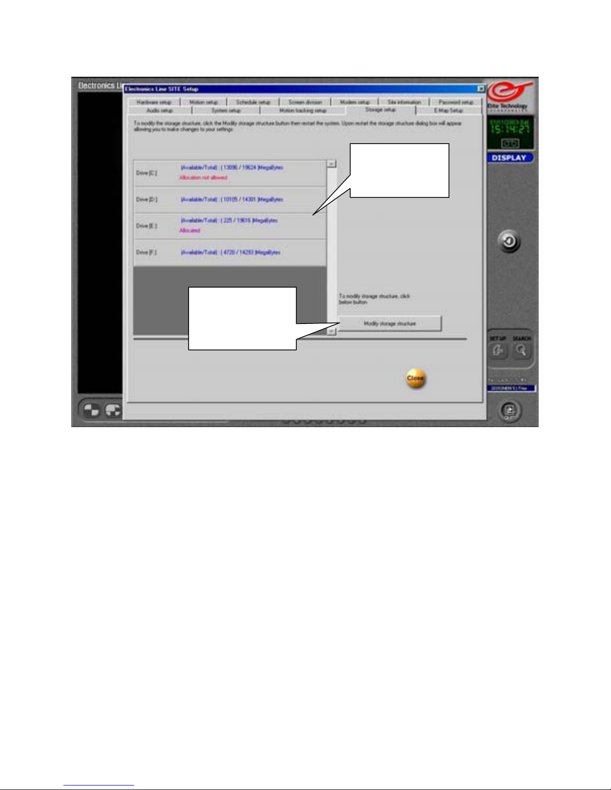
Drive Information
Identifies each hard drive installed, shows the drive size in Megabytes, and shows if the
drive has been allocated for data storage.
Modify Storage Structure
Use this option to reallocate (format) one or more hard drives.
Drive
Information
All data stored on a drive will be lost when you reallocate it.
Use this option if the DVR has indicated a memory error or if the storage structure has
become corrupted.
To reallocate a drive, click on the ‘Modify Storage Structure’ button and then click the
‘Close’ button.
Use the ‘Quit’ button (on the main screen) to turn off the DVR.
Restart the DVR.
The Storage Structure panel will appear when the DVR reboots.
72
Page 73
Storage Setup
Allocation
Buttons
Proceed
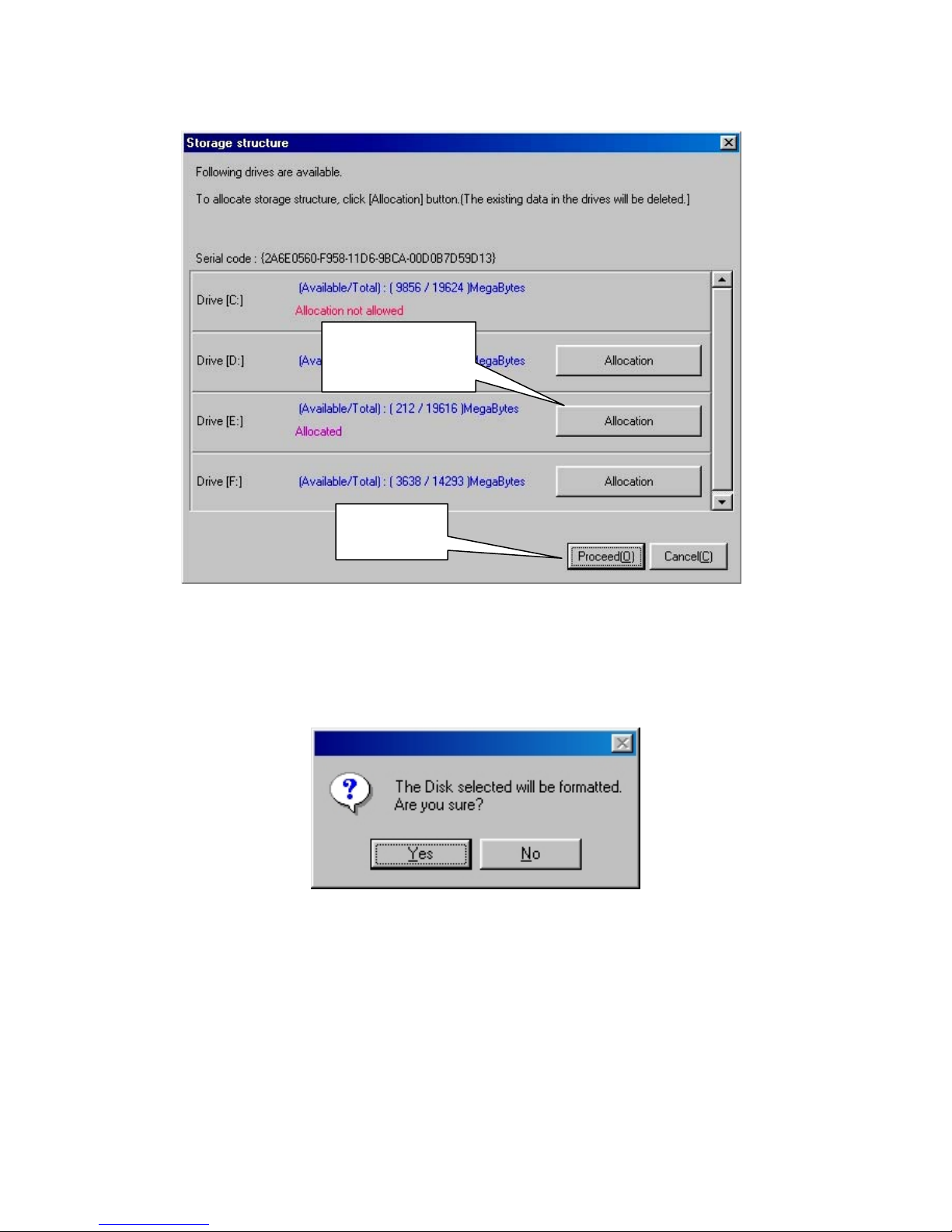
Allocation Buttons
Click on the buttons to allocate (format) the storage drives. You may select any number of
drives to allocate. Allocation is not allowed on the ‘C’ drive. (Operating System Drive)
When you have selected the drives to allocate, press the ‘Proceed’ button.
Click on ‘Yes’ to begin drive allocation. The DVR will restart automatically when the
allocation process has finished.
Remember, ALL DATA on the allocated drives will be
ERASED.
73
Page 74
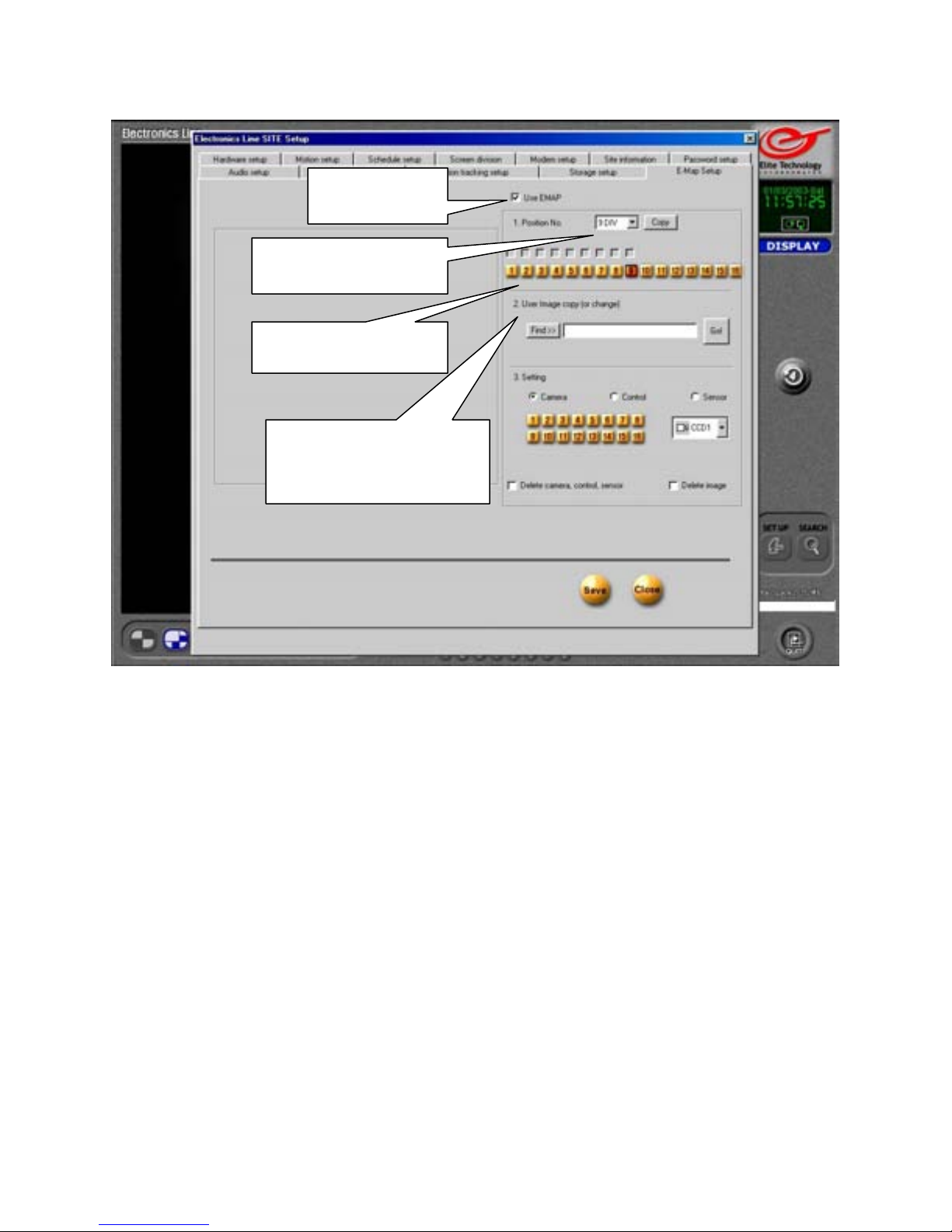
E-Map Setup
Use EMAP
Screen Division
Camera Number
User Image Copy
(Or Change)
Use EMAP
Place a check in the box to enable the EMAP function. The EMAP will allow you to place a
bitmap image (*.bmp) into a frame on the main view screen. (One camera will be replaced
by the image.) You can place icons on the image to represent the positions of your cameras,
sensors and controls. The icons will flash to indicate the associated device has been
activated. Clicking on a camera icon will open that camera to full screen view.
Screen Division
Use the drop down box to select the screen division you use on the Main Screen.
Camera Number
Click on the Camera number button to select which camera frame the EMAP will use in
the Screen Division you have selected.
User Image Copy (Or Change)
This is where you will select the image to use for your EMAP. The image must be a
Windows Bitmap (*.bmp) format. This may be created in Windows ‘Paint’ or similar
graphics editing program.
74
Page 75
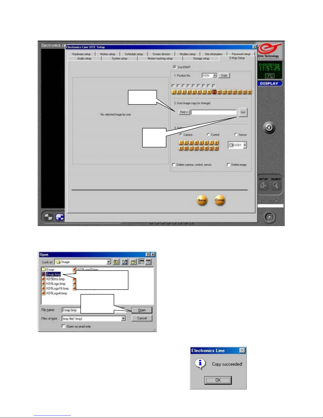
E-Map Setup
Find
Find
Click on the Find button to open the file browser.
Select Image
Open
Click on OK to finish and open your EMAP image.
Go
Select Image
Click on your image to select it.
Open
When you have selected your image, press
the Open button to open the file.
Go
Click on the Go button to copy your image to
the EMAP window.
75
Page 76
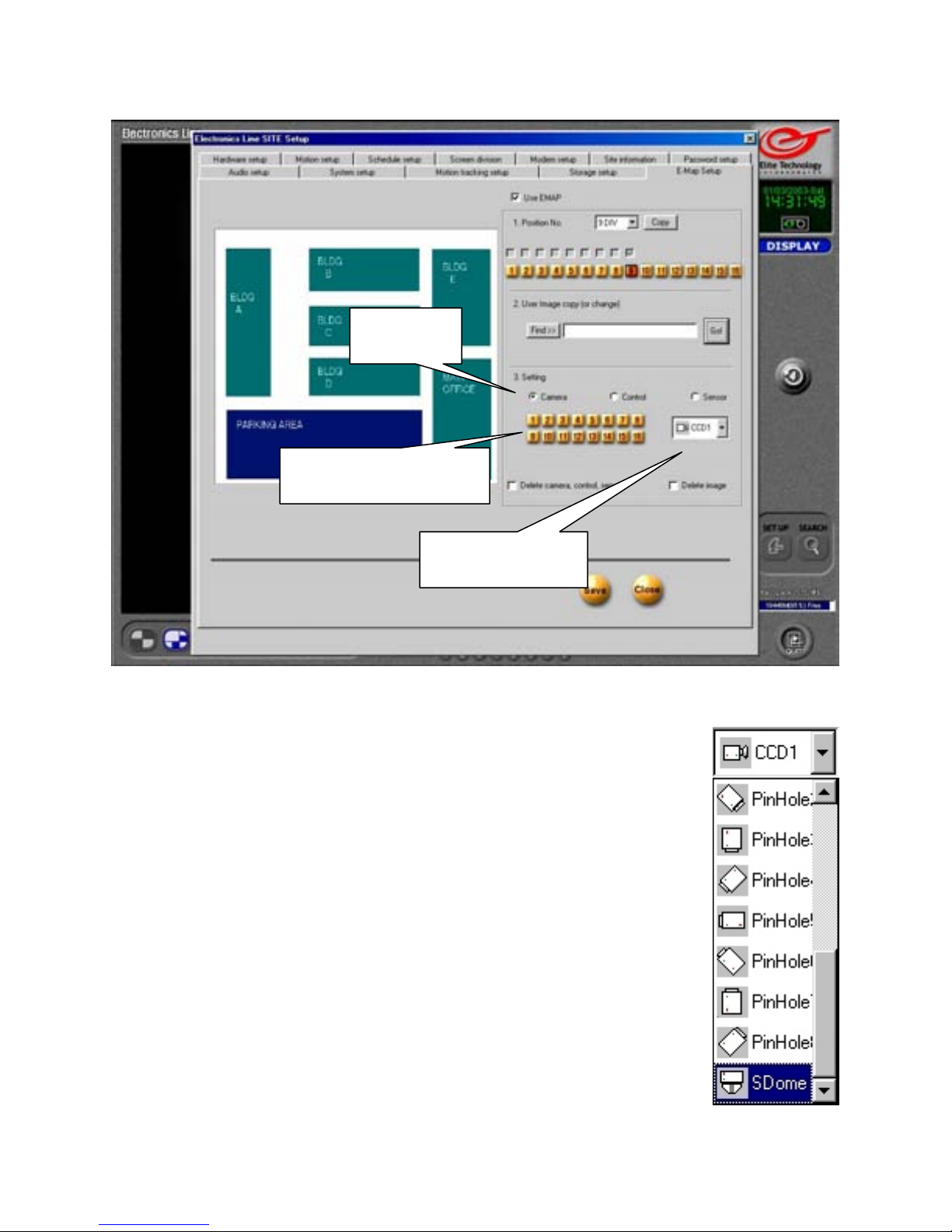
E-Map Setup
Camera
Camera Number
Camera
Choose icons for up to 16 different cameras. Select Cameras by
placing a check in the ‘Camera’ button.
Camera Number
Click on the numbered button to select the camera number.
Camera Menu
Use the drop down menu to choose a type and direction for the camera
you are representing. Click on the image in the menu and then place the
image into the EMAP by left clicking the mouse in the correct spot on the
EMAP image. If the icon is not where you
want it, move the mouse cursor and click again to adjust its position.
When the icon is positioned correctly, click on the next ‘Camera Number’
Button and choose the next camera icon from the ‘Camera Menu’
Continue until you have assigned icons to all cameras.
Camera Menu
76
Page 77
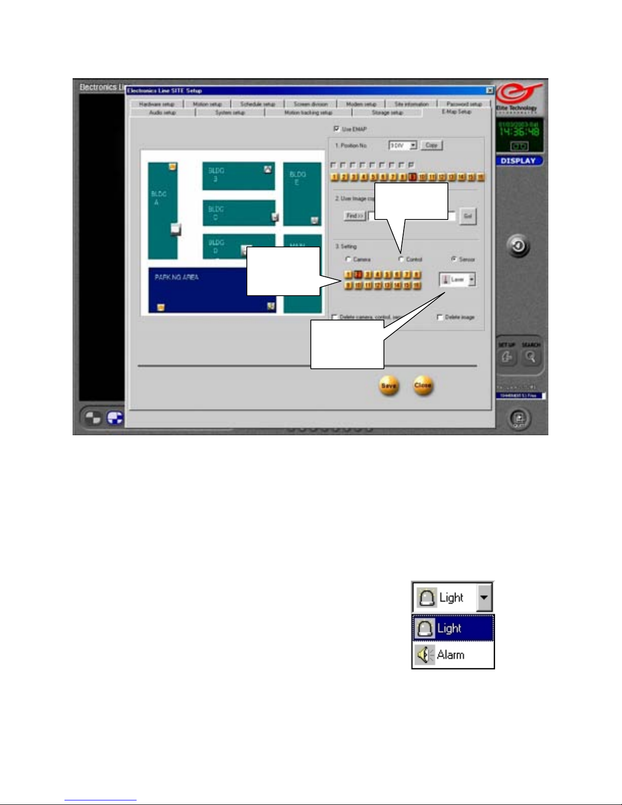
E-Map Setup
Control
Number
Control
Menu
Control
Place a check in ‘Control’ to choose icons for your control relays. You may select up to 8
control relays.
Control Number
The camera number buttons become Control Number buttons when you select Control.
Click on a numbered button to select a control.
Control Menu
Use the drop down menu to choose the correct control device .
Click on the device in the menu to select it.
Move your mouse cursor to the EMAP image and
left click on the image to place the icon.
Control
77
Page 78
E-Map Setup
Sensor
Number
Sensor Menu
Delete Camera,
Control, Sensor
Sensor
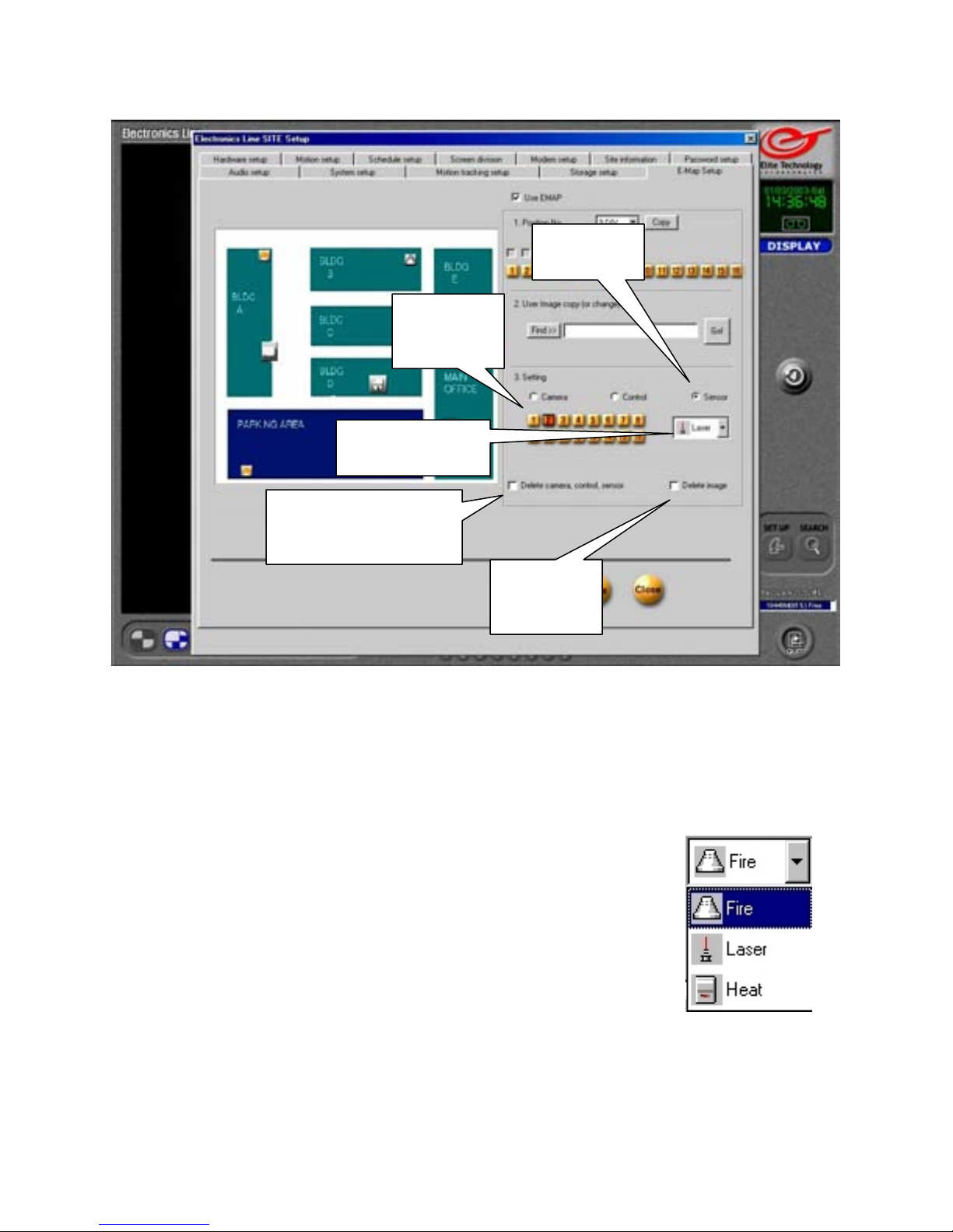
Place a check in ‘Sensor’ to choose icons for your sensors. You may select up to 8 sensors.
Sensor Number
The camera number buttons become Sensor Number buttons when you select Sensor.
Click on a numbered button to select a sensor.
Sensor Menu
Use the drop down menu to choose the correct sensor device.
Click on the device in the menu to select it. Move your mouse cursor
over the EMAP image and left click to place the icon.
Delete Camera, Control, Sensor
Place a check in the box and click on an icon in the EMAP image to
delete it .
Delete Image
Place a check in the box and click on the EMAP image to remove it.
78
Sensor
Delete
Image
Page 79
E-Map Setup
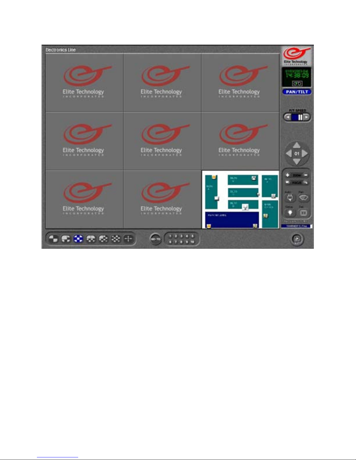
When you have finished setting up your EMAP, save your settings and close out of Setup.
When you return to the Main Screen your EMAP will appear in the camera position you
selected. The icons will flash to indicate when the device has been activated.
If you click on a camera icon, the live picture from that camera will jump to Full Screen.
If that camera is a Pan/Tilt /Zoom camera, the P/T/Z interface will automatically appear as
well.
79
Page 80
Pan Tilt Zoom Controls
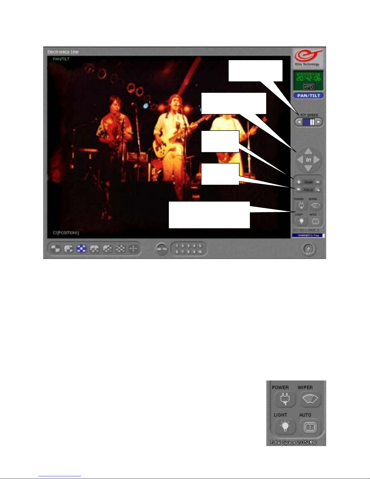
Camera Specific
Controls
Move Camera
Zoom
Focus
P/T Speed
Use the left and right arrows to adjust the speed of the Pan/Tilt/Zoom camera.
Move Camera
Press the Up, Down, Left, and Right arrows to move the Pan/Tilt/Zoom camera.
Zoom
Zoom the picture in or out by clicking on the + or – buttons.
Focus
Adjust the focus of the camera by clicking on the left or right buttons
Camera Specific Controls
These controls will change according to the P/T/Z camera you have
connected. Consult your camera manual for instructions on these
features.
Note: the picture on the buttons will not change, the text above the
button will change to show the available options for your camera.
P/T Speed
80
Page 81
Pan Tilt Zoom Controls
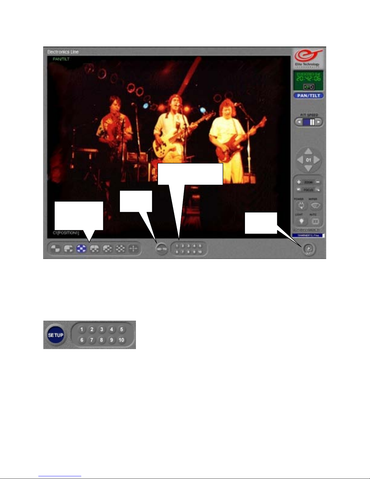
Preset Selector
Go To
Screen
Divisions
Preset Selector
The preset selector allows you to select up to 10 different pre-programmed positions to
move the P/T/Z camera to. Click on a numbered button to move the camera.
Go To
Click on the ‘Go To’ button to enter your pre-set camera positions.
The ‘Go To’ button will change to ‘Setup’.
Use the Pan/Tilt/Zoom controls to move the camera to the
first position. Click on the ‘1’ button to set the position.
Move the camera to the next position and click on the ‘2’
button to enter that position. You may set up to 10 pre-set positions.
Click on the ‘Setup’ button to save your changes and test the presets you have entered.
Screen Division
Click on a screen division button or click on the image to return to normal view mode.
Clicking on the image will toggle between normal and full screen mode.
Quit
Click on the ‘Quit’ button to close the Pan/Tilt/Zoom controls and return to the Main
Screen.
Quit
81
Page 82
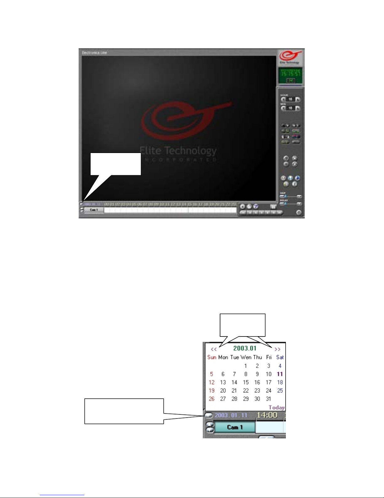
Search Mode
Calendar
Search Mode allows you to quickly and easily access recorded data. If you capture an event
that you need to copy or backup, you can transfer your video to a variety of removable
media devices including floppy disks, CD-R, CD-RW disks, External hard drives, and
network storage devices.
The transferred images may be ‘Watermarked’ to prevent tampering and allow
admissibility as evidence in the court system.
Calendar
To use Search Mode click on the Calendar button to show the calendar.
Use the Arrows to select the month, then click
on the day you wish to search to select it.
Days which have recorded data will show up
In bold type.
Calendar Button
Arrows Arrows
82
Page 83
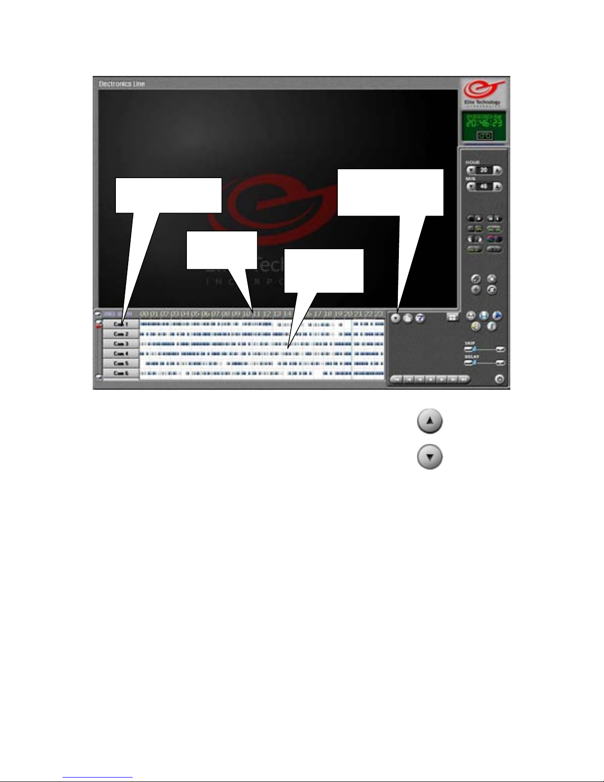
Search Mode
Select Cameras
Timeline
Recorded
Data
Show / Hide Cameras
Click on the up arrow to show recorded data and camera buttons.
Click on the down arrow to hide recorded data and camera buttons.
(The button changes according to the panel status.)
Select Cameras
Click on the buttons to select the cameras you want to search. Select up to 16 cameras to
search at the same time.
Timeline
Shows the entire selected day in 1 hour increments. Time is shown in 24-Hour format
beginning with hour 00 (Midnight ~ 12:59am) and ending with hour 23 (11:00pm ~
11:59pm)
Recorded Data
The horizontal lines show when data was recorded. The lines may be different colors
depending on what type of recording was used, or what triggered the recording.
Blue = Motion
Red = Sensors
Pink = Continuous
Green = Pre Alarm
Show / Hide
Cameras
83
Page 84
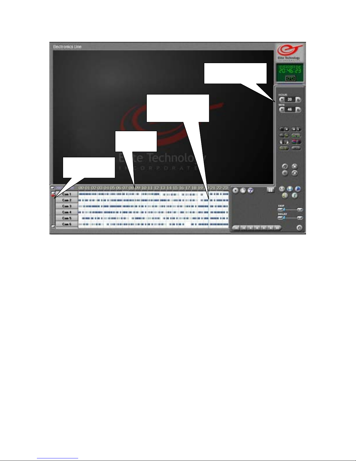
Search Mode
Search Time
Indicator
Timeline
Scroll Bar
Hour / Minute
The hour and minute values show the current time being searched. Left click on the up and
down arrows to change the values. The values will also change when you click in the data
area to move the Search Time Indicator.
Search Time Indicator
A thin blue vertical bar will indicate the current time being searched. Left click in the data
area to move the bar to a different hour or minute.
Timeline
You may left click on the timeline to expand (magnify) the recorded data area. This can
help you find a specific time more easily. You may expand the data area 2 times. Click
again and the timeline will return to normal size.
Scroll Bar
Use the scroll bar to show the rest of your cameras and data areas so you may select them
to search.
Hour / Minute
84
Page 85
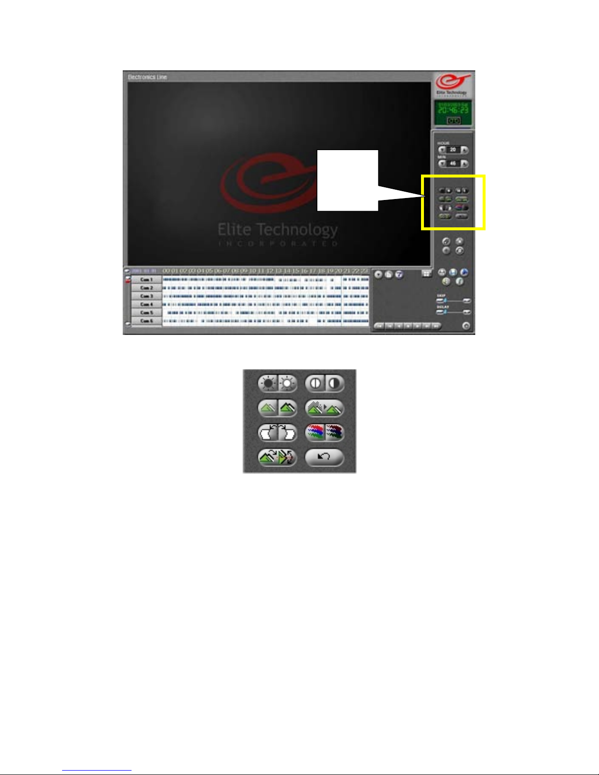
Search Mode
Still
Image
Tools
Still Image Tools
Brightness Contrast
Sharpness Noise Reduction
Deskew Gamma Correction
Rotate Undo
Brightness = Lighten or darken the image
Sharpness = Sharpen or remove blur from the image.
Deskew = Straighten the image if the picture appears tilted left or right.
Rotate = Rotate the image 90 degrees at a time.
Contrast = Increase or decrease the amount of difference between light and dark areas.
Noise Reduction = Reduce the speckling that can occur when you zoom in, increase
contrast, or sharpness of the image.
Gamma Correction = Adjust the color saturation of the image. If some colors are too
bright or distorted, you can reduce the color without changing it.
Undo = Undo all changes and return to the original image.
(Stop Playback and select a single image to use Still Image Tools)
85
Page 86
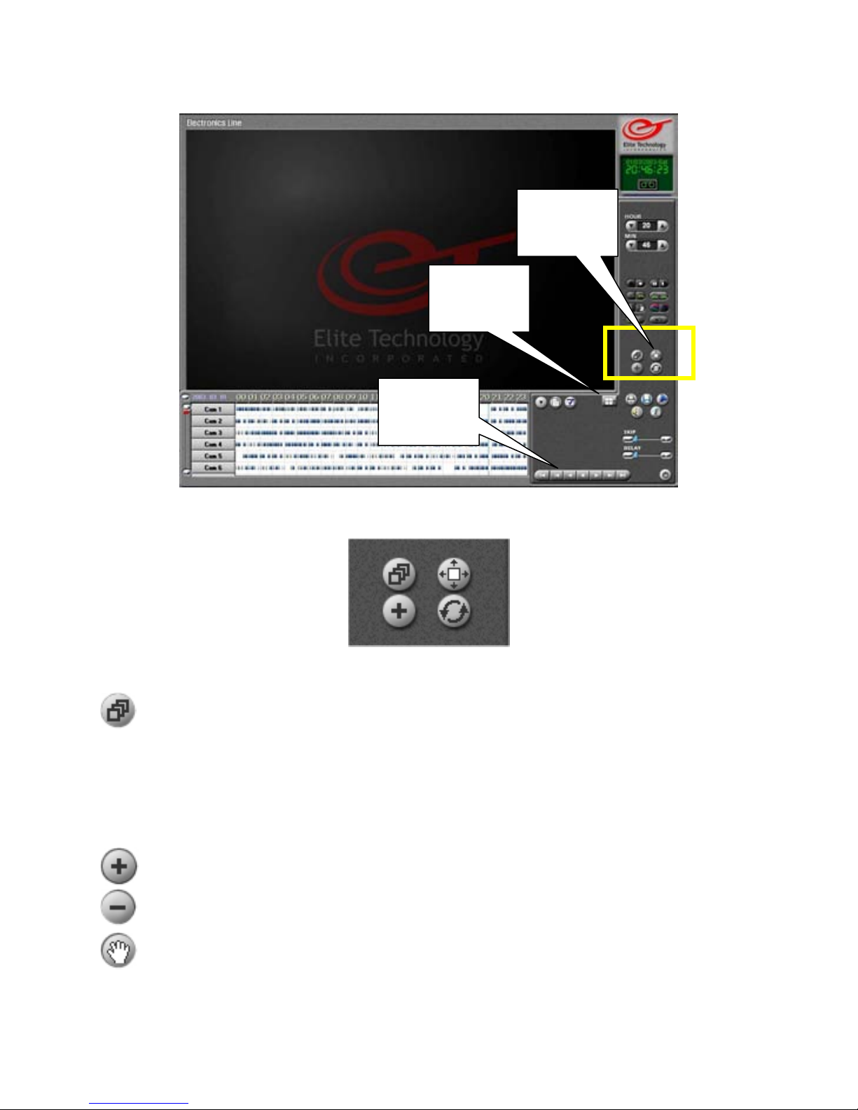
Search Mode
Screen
Division
Playback
Controls
Search Tools
Panorama Enlarge Image
Zoom Tool Refresh Data
Panorama
Use ‘Panorama’ mode to view a single camera in a series of sequential frames. Select
a camera and time, and then select a screen division to determine how many
sequential frames will be shown.
Zoom Tool
The Zoom Tool performs 3 different functions. Left click on the button to change the
function from zoom in, to zoom out, to the hand tool.
Stop playback and select an image (by clicking on it) to use the zoom tool.
Right click on an object in the image to zoom in on it.
Right click on the image to zoom out.
Right click and hold down the mouse button to ‘grab’ the image and move it around
when you are zoomed in.
(Stop playback and select a single image to use the Zoom tool.)
Search
Tools
86
Page 87
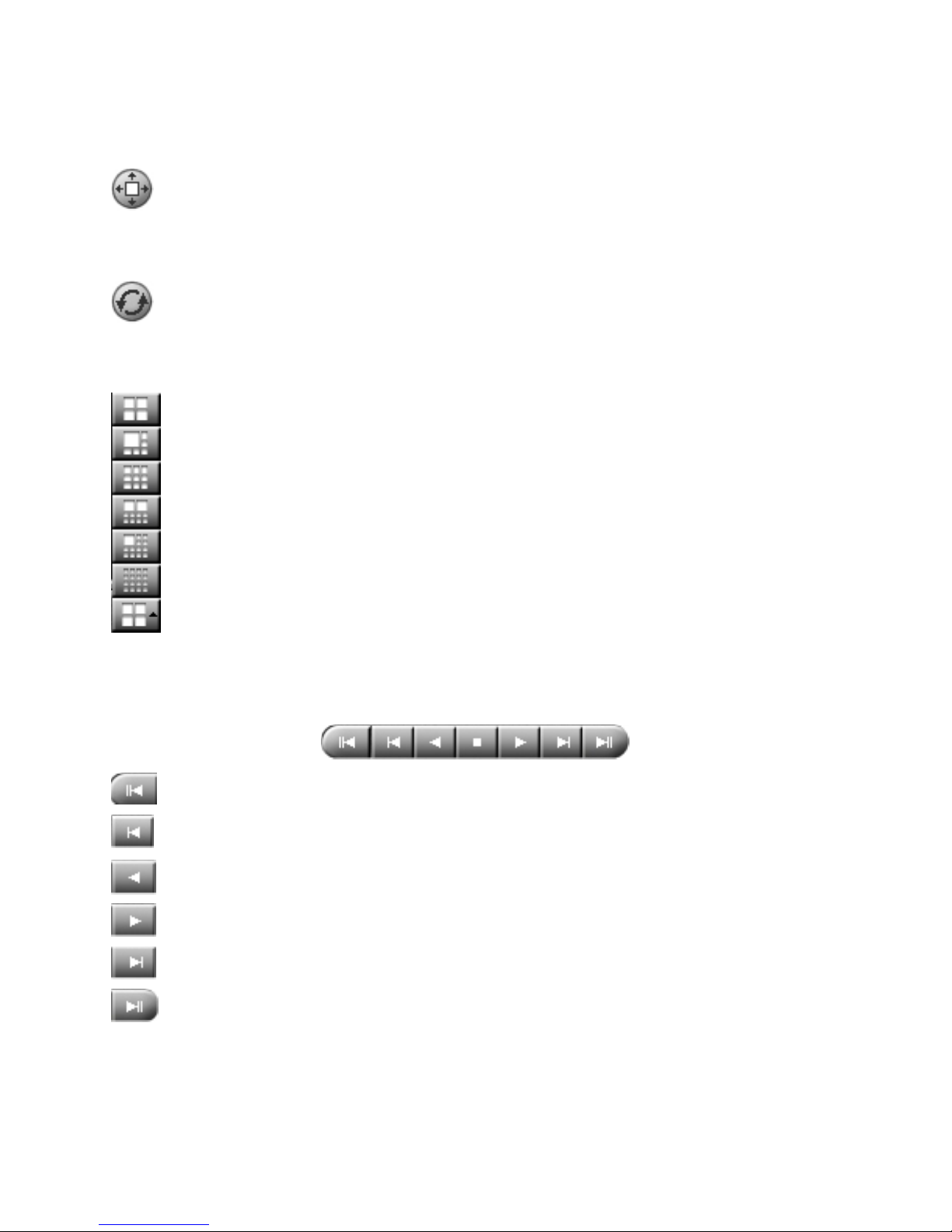
Search Mode
Enlarge Image
Left click on the button to enlarge the selected image. Click again to enlarge the
image again. When the image is at maximum size (Full screen), click again to return
to default recorded size.
Refresh Data
Left click on the button to refresh (update) the Data Area to include the most
recently recorded data. (DVR is set to record during search by default, however
data area does not automatically update while current day is selected.)
Screen division
Click on the up arrow to show the screen division selector.
Click on the screen division to apply it to the Search
screen.
In ‘Panorama’ mode this will determine the number of sequential frames to be
shown on a camera.
In standard ‘Search’ mode, you can search up to 16 cameras simultaneously.
NOTE: When searching multiple cameras at once, some camera images may be
blank or show a still image at times. This is normal. This means there is no
recorded data for those cameras at that minute of playback. (Cameras only record
when there is motion)The still image is the last image recorded by a camera.
During playback, the last image shown will remain in the frame until a new image
replaces it.
Playback Controls
Play in reverse
Play
Play forward frame by frame
Skip to the end of recorded data
Skip to beginning of recorded data
Play in reverse frame by frame
87
Page 88
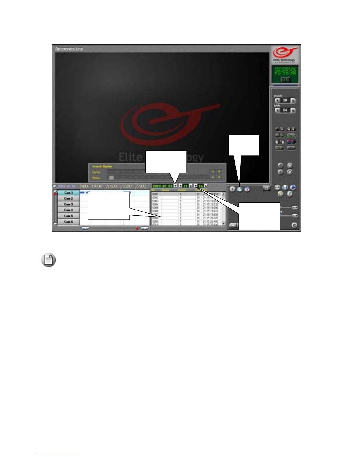
Search Mode
Calendar
Index
Search
Index
by frame list of images captured for the currently selected minute. You may left click
on an entry in the list to show that image in the view screen.
Click on the Index button to open the index search. The index search shows a frame
Calendar
Use the drop down arrow to show the calendar. Select the date you wish to search by left
clicking on it.
Hour / Minute
Use the up and down arrows to select the hour and minute you wish to search.
Index Search
List shows the order in which the images were captured.
Shows the motion or sensor device number that triggered the image capture.
Shows which camera captured the image.
Shows the exact time the image was captured.
Note: Index search is disabled when a single camera is selected on the view
screen. Search screen must be in default view to use index search.
Index
Hour /
Minute
88
Page 89
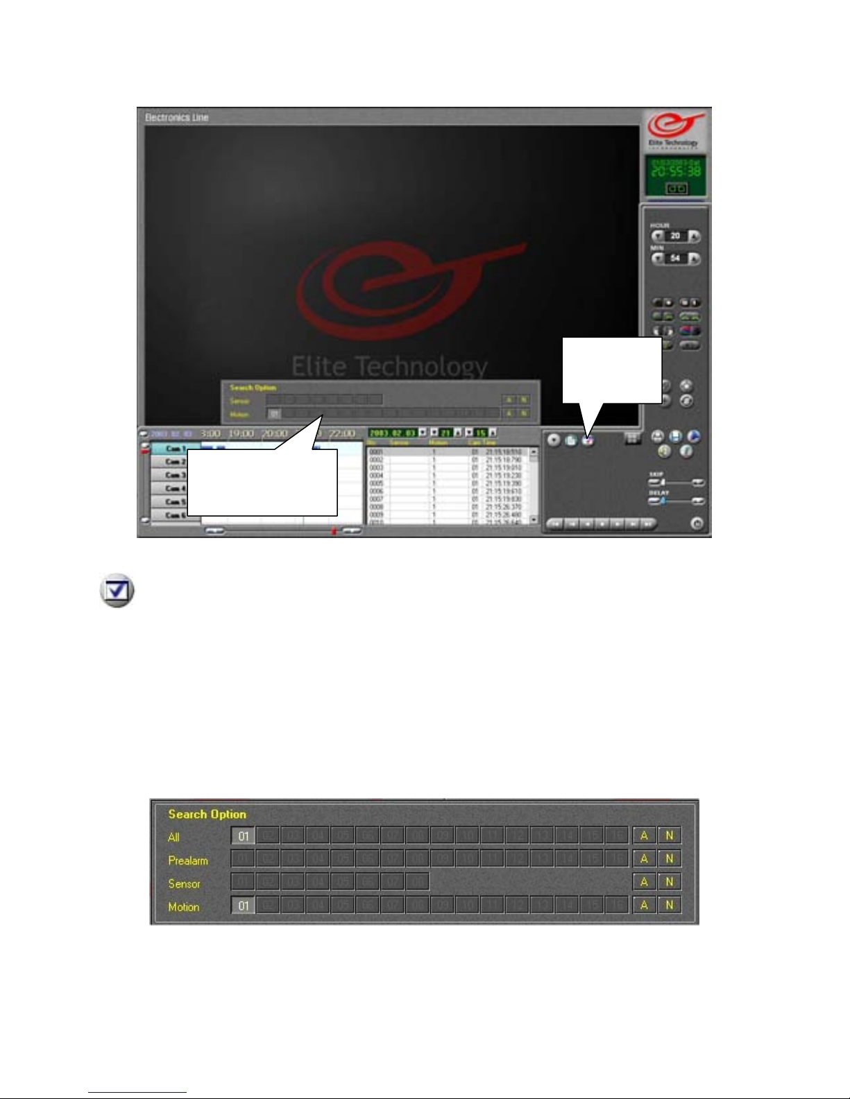
Search Mode
Option Panel
(Index Search)
Search Options
The Search Options Panel allows you to filter the information shown in the Index
Search list and the Recorded Data Area .
Click on the Search Options button to toggle the Search Options Panel on or off.
Option Panel
All= Click on a camera number to show data from all record modes for that camera.
Prealarm= Click on a camera number to show data recorded in Prealarm mode.
Sensor= Click on a sensor number to show data recorded in Sensor mode.
Motion= Click on a camera number to show data recorded in Motion mode.
A= Select all devices.
N= Select no devices.
Option Panel in Default Search Mode
Search
Options
89
Page 90
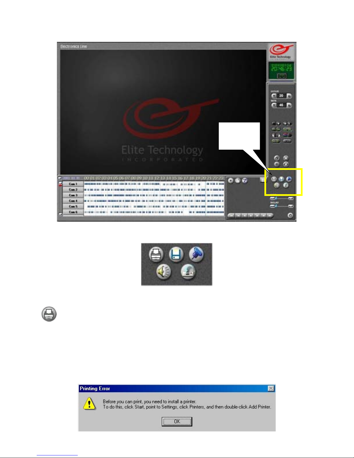
Search Mode
Print Backup Bookmark
Audio Setup Toggle Recording
Print
Left click on the Print button to print the currently selected still image.
Stop playback and select an image by left clicking on it.)
The printed image size is determined by the image size on the screen. Use the ‘Enlarge
Image’ tool (p.86) to set the image size.
The printed image will show the image, the site code of the DVR (p.41), the date and time
the image was taken, the camera number, and the watermark status.
You must have a printer installed to use the Print function.
If you receive this error, no printer is installed.
Backup
Tools
90
Page 91
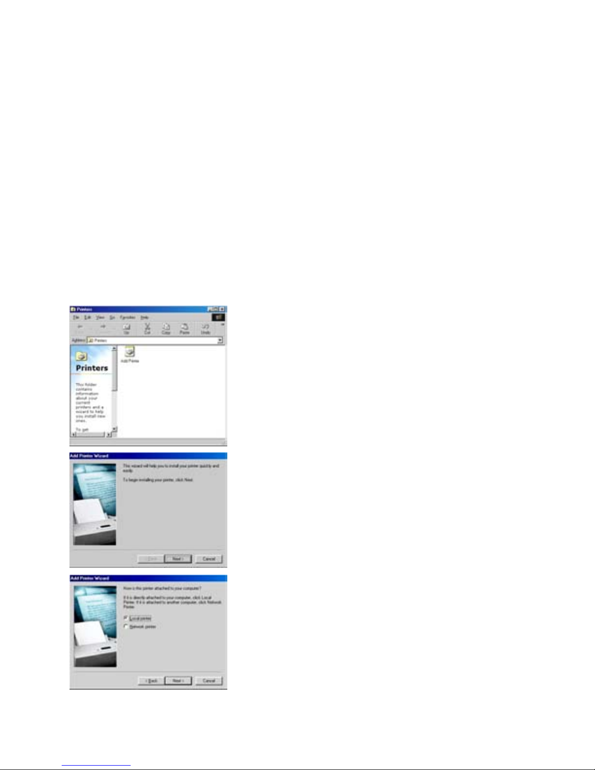
Search Mode
Installing a Local Printer
1. Turn off the DVR by left clicking on the ‘Power’ button on the Main View Screen.
2. Connect your printer to the DVR. (25-pin parallel or USB cable)
3. Turn on the printer.
4. Restart the DVR.
5. The DVR will detect the printer when it starts up and prompt you for the driver
installation disk.
6. Follow the onscreen directions to install the printer and set it as the ‘Default’ printer.
7. When the printer installation is finished the DVR will start up normally.
If the DVR does not detect the Printer when Starting Up
1. Make sure the printer is connected to the DVR.
2. Make sure the printer power cable is plugged in and the printer is turned on.
3. Restart the DVR. If the printer is still not detected, proceed to step 4.
4. Press the ‘Windows’ key on your keyboard to access the Start Menu.
5. Choose ‘Settings’ and then ‘Printers’.
The Printers window will open. Double click on the ‘Add
Printer’ icon.
Click ‘Next’ to begin installation.
Choose ‘Local Printer’ if the printer is physically
connected to the DVR by a 25-pin parallel or USB printer
cable.
Choose ‘Network Printer’ if you plan to use a shared
printer on a LAN.)
91
Page 92
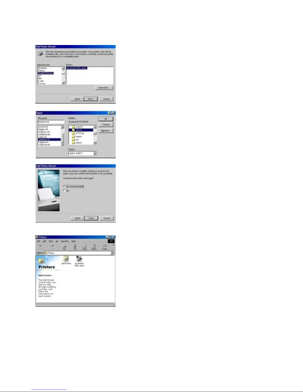
Installing a Local Printer (cont.)
Search Mode
Choose your printer from the list or choose the ‘Have
Disk’
button if you have a driver installation disk.
Browse to the location of your driver and click OK to
install the printer.
Print a test page to insure installation was successful and
the printer will print correctly.
Check to make sure the printer is selected as the Default
printer. If so, close the Printers window. Installation is
complete.
The ‘Print’ button in search mode will use the default
printer when you print an image.
92
Page 93
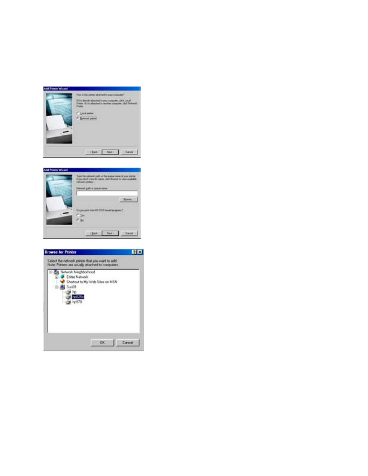
Search Mode
Installing a Network Printer
Follow the same steps to open the ‘Printers’ window and double click on the ‘Add Printer’
icon to begin installation.
Choose ‘Network Printer’ instead of ‘Local Printer’ and
click the ‘Next’ button
Click on the ‘Browse’ button to search the local network
for a shared printer.
Click on the shared printer and then click on the OK
button to select it.
If you are prompted for drivers, contact your network
administrator for the correct drivers.
Finish Setup by printing a test page and closing the
‘Printers’ window.
93
Page 94
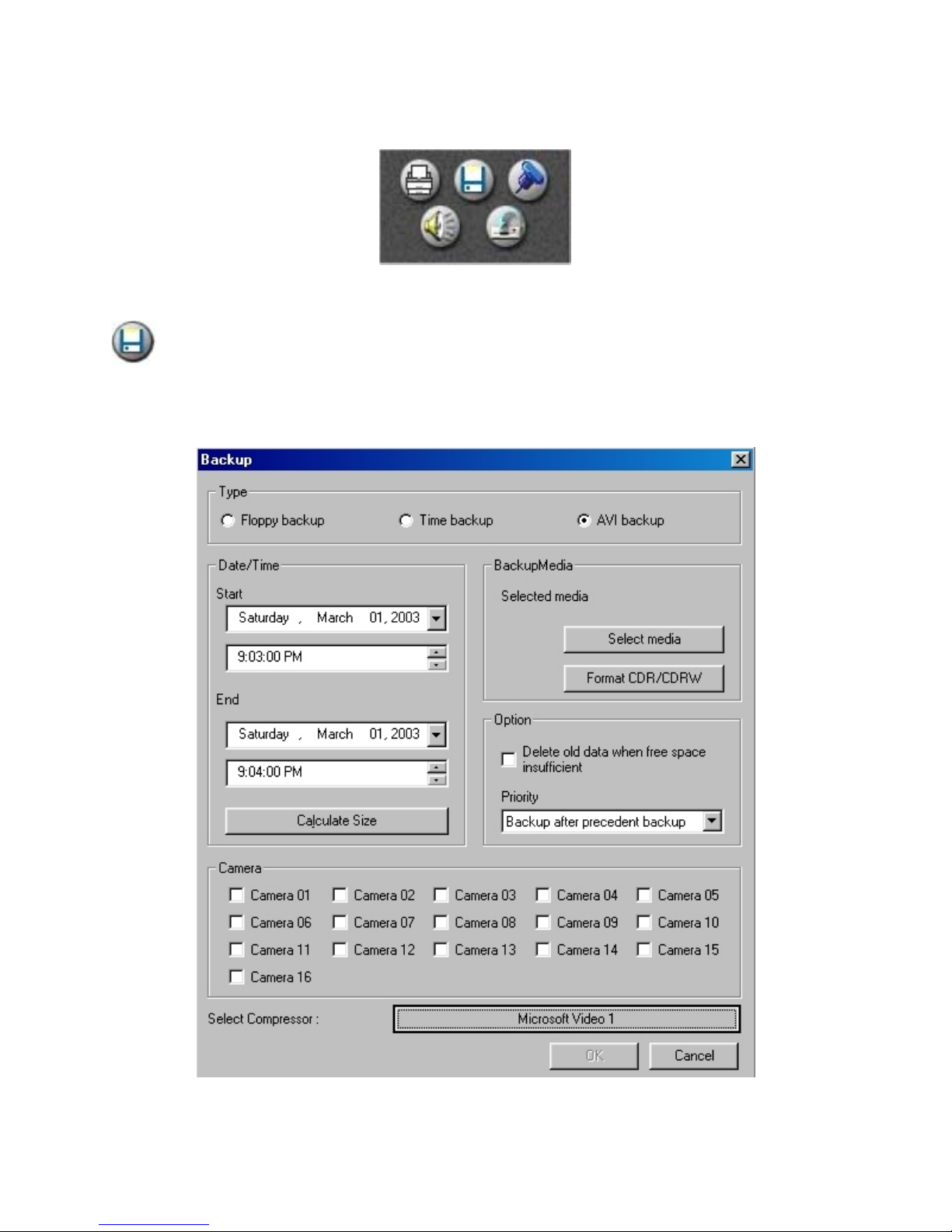
Search Mode
Print Backup Bookmark
Audio Setup Toggle Recording
Backup
or create a Time Backup of an event. An AVI file may be viewed on any computer
with Windows Media Player or similar moving image viewing software.
A Time Backup may only be viewed on a computer with the Electronics Line Center
software installed.
Click on the Backup button to save a single still image, create an AVI file of an event,
94
Page 95
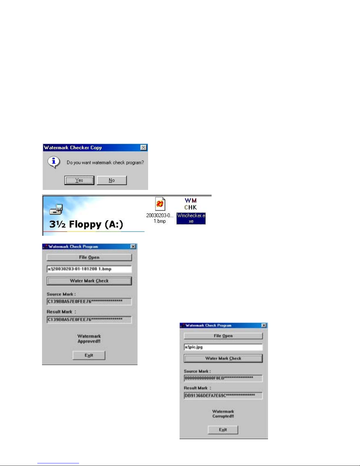
Search Mode
Floppy Backup
Select ‘Floppy Backup’ to send a single image to the floppy disk. You may copy multiple
images to the disk until the disk is full. You may use two different formats when saving to a
floppy disk. Either format may be viewed on any computer.
A *.bmp image is better quality but a larger file size.
A *.jpeg image is a lesser quality but smaller file size. (You can save more images on a
single disk.)
Choose the format for the image in ‘Setup’ on the ‘Site Information’ page. (p.42)
(Image Transfer to Floppy Disk ~ Tick for BMP ~ Untick for JPEG)
When you select Floppy back up and the image is watermarked, the DVR will ask if you
want the Watermark Checker program copied to the disk as well.
Select Yes to copy the file to the disk along with the
image.
Double click the ‘WM CHK’
icon to open the Watermark
Check software.
Click on the ‘File Open’ button to select the image.
Browse to the image and click on it to select it. The image
name and directory will appear in the file name box.
Click on the ‘Watermark Check’ button to test the
integrity of the image. If the image has not been tampered
with, a ‘Watermark Approved’ message will appear.
If the image has been changed in any way
a ‘Watermark Corrupted’ message will
appear.
95
Page 96
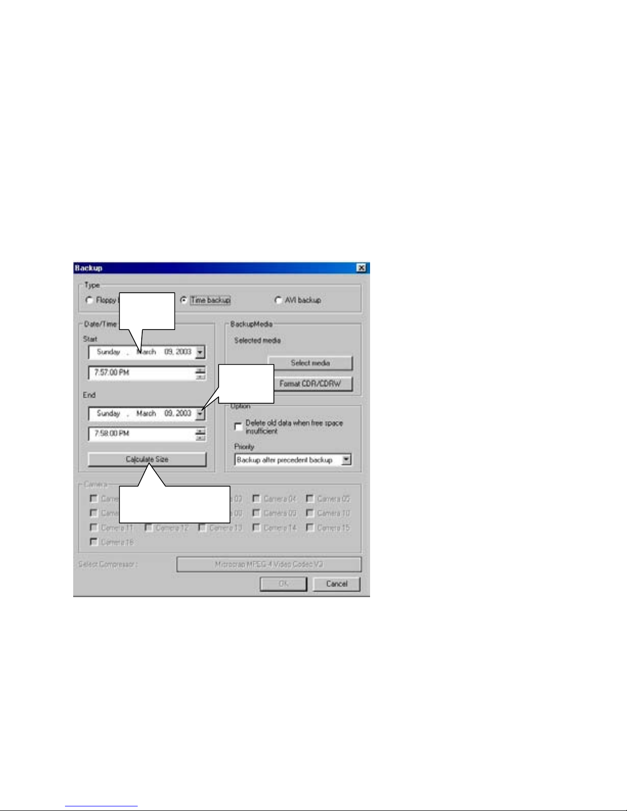
Search Mode
Time Backup
Select Time Backup when you want to save large amounts of recorded data for future
review on a remote computer with the “Center” software installed.
(An ‘AVI’ backup will only allow 5 minute segments to be recorded at one time, thereby
making it impractical for multiple day backups.)
Time backup has no limitation on the length of time you can select. The only limitation is
the amount of backup storage space you have available on disk.
The data saved in a Time backup is a copy of the information on the storage
drive of the DVR. It is a proprietary file system and can only be viewed on a
computer with the ‘Electronics Line Center’ software installed.
When you select the Time
backup option, the data from all
Start
End
Calculate Size
to create the backup. Make sure you have sufficient disk space to record the backup before
proceeding.
A standard CD-R or CD-RW disk will hold up to 700MB of information. You may be able
to back up less than a day or more than a week onto a single disk depending upon your
camera image quality and resolution settings, and how much motion each camera records.
Use the Calculate Size button to determine how much time you can save to a disk.
Important!
Do not back up data to the ‘C’ drive. Backing up to the ‘C’ drive
can interfere with the operation of the DVR.
cameras is automatically saved.
You may not select individual
cameras to backup.
Start
Set the starting date and time for
your backup. Notice that you
must convert the 24-hour time
format of the DVR to 12-hour
(AM or PM).
End
Set the ending date and time of
your backup.
Calculate Size
When you have entered your
Start and End times, click on the
Calculate Size button to estimate
the amount of disk space needed
96
Page 97
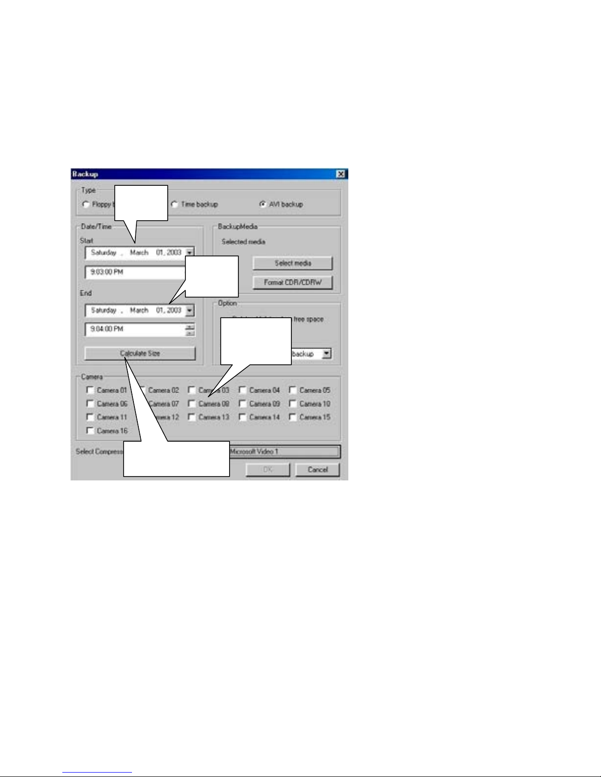
Search Mode
AVI Backup
Select AVI backup when you have isolated a short event you wish to save.
AVI backup is limited to a 5 minute segment.
You may select individual cameras to back up.
An AVI backup file may be played on any computer with Windows Media Player or
similar viewing software. The ‘Electronics Line Center’ software is not needed.
Start
End
Select
Cameras
Calculate Size
A separate AVI file will be created for each camera selected.
Calculate Size
Use the Calculate size button to estimate the disk space needed to save the backup.
AVI files are substantially larger than Floppy backup or Time backup files.
Be careful not to try to back up more data than you have disk space available for.
A standard CD-R or CD-RW will hold up to 700MB of data. If you exceed this size when
recording to a CD, either select fewer cameras or shorten the length of time for the backup.
Important!
Do NOT select the ‘C’ drive or any drives that are allocated for data storage
by the DVR for backup. Backing up to the ‘C’ drive or allocated storage
drives will interfere with the operation of the DVR.
Select AVI Backup to create an
AVI file.
Start
Set the starting date and time for
your backup. Notice that you
must convert the 24-hour time
format of the DVR to 12-hour
(AM or PM).
End
Set the ending date and time of
your backup. If more then 5
minutes is selected, the End time
will be automatically adjusted to 5
minutes after the Start time.
Select Cameras
Place a check in the box for the
cameras you wish to back up. You
may select any combination
cameras from 1 to all 16.
97
Page 98
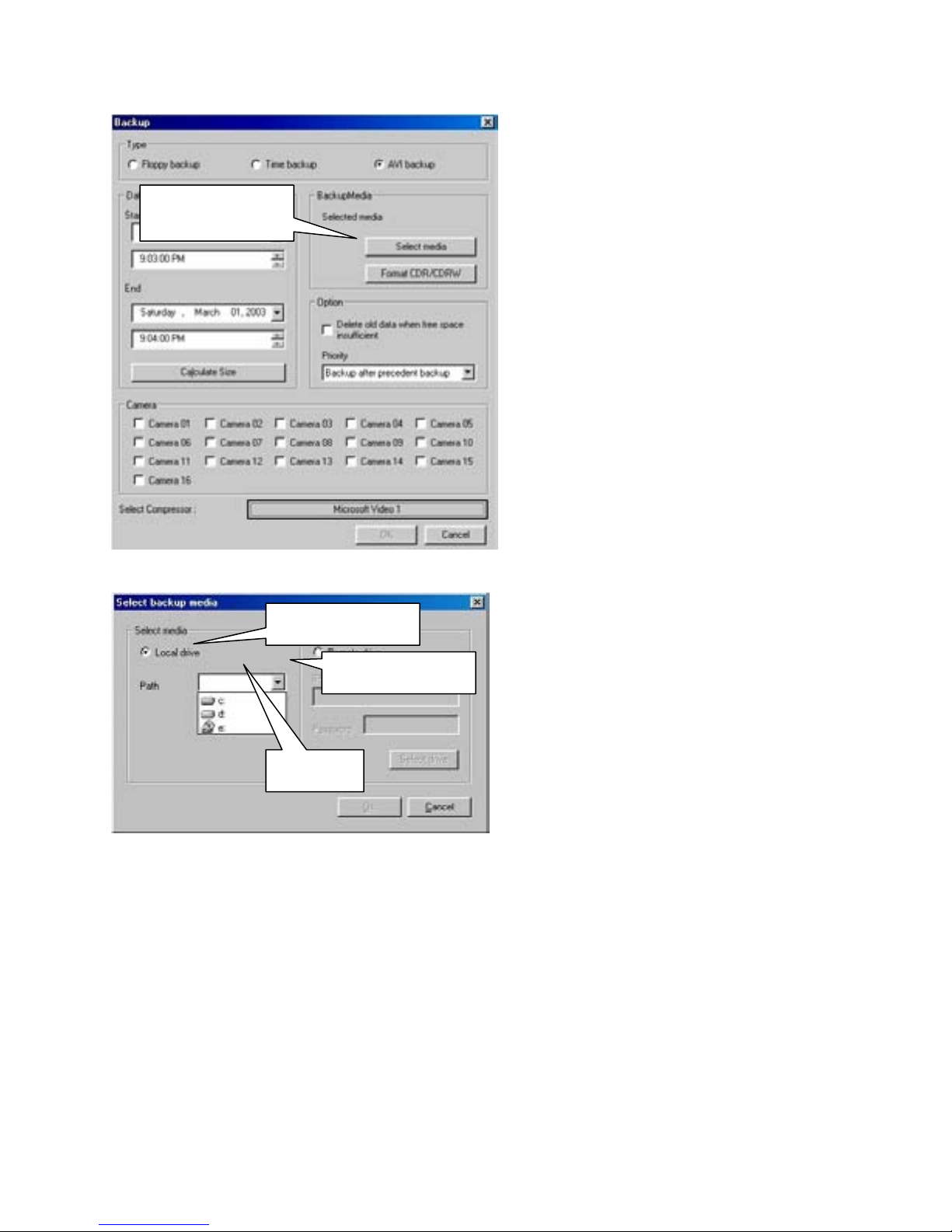
Search Mode
Select Media
Select the drive to save the backup on.
Select Media
Local Drive
Down Arrow
Path
Path
Click on the ‘Down Arrow’ to show the available drives installed on the DVR. Click on a
drive to select it as the backup drive. Click on the OK button to confirm your choice. The
Select Backup Media panel will close.
Do NOT select the ‘C’ drive or any drives that are allocated for data storage
by the DVR for backup. Backing up to the ‘C’ drive or allocated storage
drives will interfere with the operation of the DVR.
You may save data to:
Floppy disk (Still images only)
External disk (Zip, Jazz, etc.)
External Hard Drive
Mapped Network Drive
Remote IP Address
CD-R / CD-RW
Optional DVD-R
Click on the Select Media button to
choose where to save your backup.
The ‘Select Backup Media’ panel will
appear.
Local Drive
When you choose the ‘AVI Backup’
option you may select a drive that is
physically installed on the DVR. This can
be an internal or external hard drive,
mapped network drive, “ZIP” or other
removable drive, or a formatted CD-R /
CD-RW disk.
98
Page 99
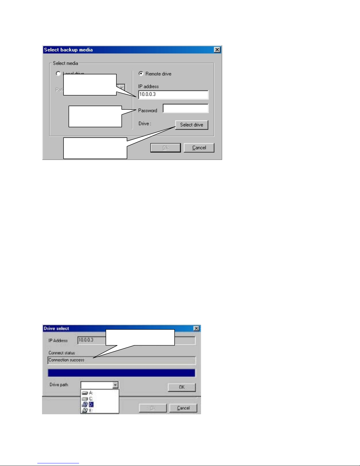
Search Mode
Remote Drive
When you choose the ‘Time
Backup’ option you may
IP Address
Password
Select Drive
Note:
drive path as an installed drive. The ‘Remote Drive’ path can connect to any computer via
the LAN (Local Area Network) or the WAN (Wide Area Network) including the Internet if
the backup computer has a Network, DSL, or Cable Modem connection with a fixed, or
‘Static’ IP address.
A network drive mapped through “Windows” networking will appear in the ‘Local’
IP Address
Enter the ‘Internet Protocol’ address of the remote computer you wish to backup your data
to. (The remote computer must have the K-Remote Backup Server software running or the
connection will fail.)
Password
Enter the password (if any) that you have set up in the K-Remote Backup Server software.
Select Drive
When you have entered the IP address and password of the remote computer, click on the
‘Select Drive’ button to connect.
The Drive Select panel will open to
Connect Status
show your connection status. If the
connection was successful, the
‘Connect Status’ box will show
‘Connection success’. If the IP
address is not correct, or the KRemote Backup Server is not
running on the remote computer,
the ‘Connect Status’ box will read,
‘Connection Fail’.
select a remote, or network
drive to backup to.
The remote computer
must have the
‘Electronics Line Center’
software installed and
the ‘K-Remote Backup
Server’ running
.
99
Page 100
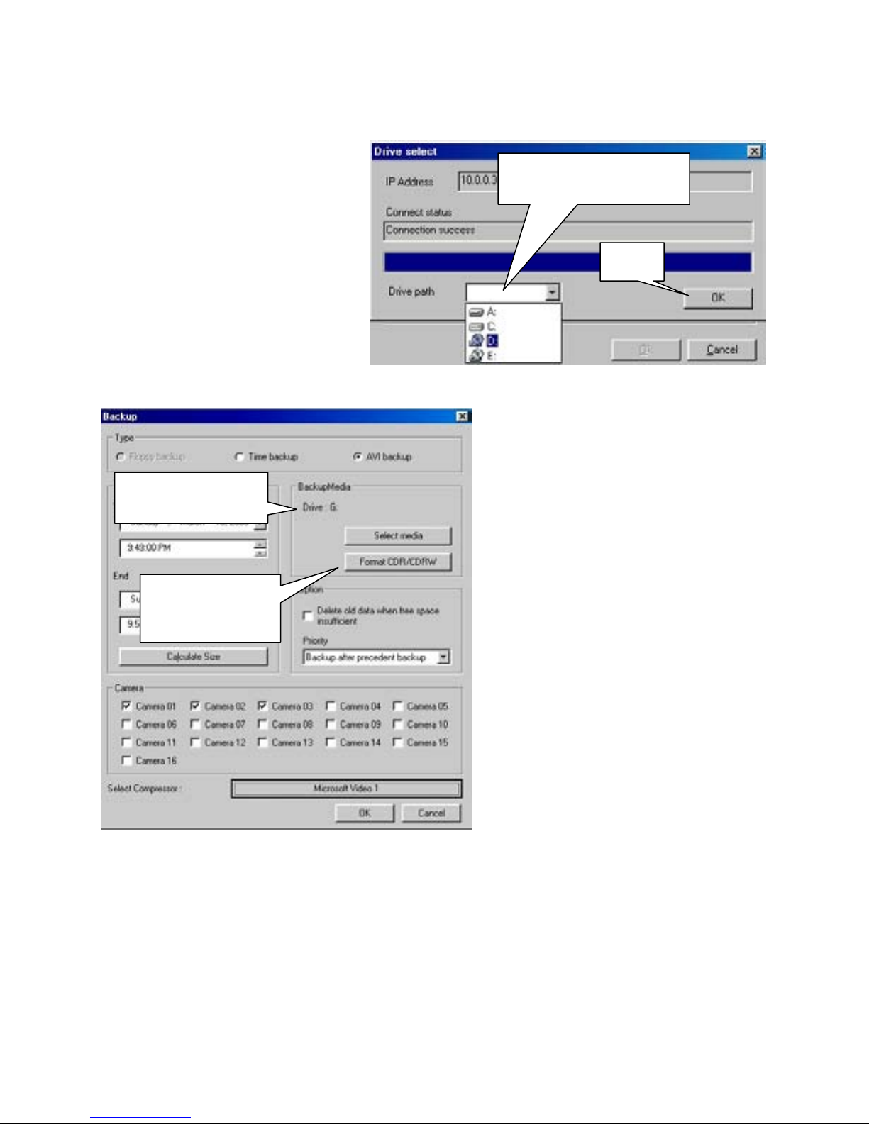
Search Mode
Remote Drive Path
When you successfully connect to
the remote K-Network Backup
Server, you will be able to select a
backup drive from the drop down
list. Click on the drive to select it.
The drive will appear in the ‘Drive
Path’ window.
OK
When you have selected a backup
drive, click on the ‘OK’ button to
confirm your choice. The ‘Drive
Select’ panel will close.
Selected Media
Format
CDR/CDRW
To format a CDR/CDRW, insert a blank disc into the CD tray and close the tray. If the
‘Roxio Project Selector’ (Easy CD Creator 5 Basic) or ‘Direct CD’ format utility do not
start automatically, click on the ‘Format CDR/CDRW’ button to start ‘Direct CD’.
100
Remote Drive Path
OK
Selected Media
When you have chosen a drive to save
your backup to, that drive will appear
in the Backup Media box. If all of
your other settings (Start/End times
etc.) are correct you may click on the
OK button to begin the backup.
Format CDR/CDRW
If you choose to backup to a CD you
MUST format it FIRST.
You may back up to a
CD-R (CD Recorder)
CD-RW (CD Rewriteable)
Or Optional DVD recorder
Formatting times vary for each type of
disk.
CD-R Approx. 15 seconds
CD-RW Approx. 30 minutes
DVD-R Approx. 2+ hours
 Loading...