

Elite Simulation S623T Operator's Manual

OPERATORS MANUAL
ELITE MODEL S623T HELICOPTER
1997 - 2013, Elite Simulation Solutions AG, all rights reserved

Table of Contents
SECTION 1 TECHNICAL DESCRIPTION SUMMAR Y.........................................................................................5
1.1 General....................................................................................................................................................5
1.2 Scope.......................................................................................................................................................5
1.3 General Confi guration............................................................................................................................6
1.3.1 Cockpit..............................................................................................................................................6
1.3.2 Instructor Station...............................................................................................................................7
1.3.3 Computer System.............................................................................................................................7
1.4 Maintenance and Support......................................................................................................................8
1.4.1 Documentation..................................................................................................................................8
1.4.1.1 Operating Manuals......................................................................................................................................8
1.4.1.2 Maintenance Manuals and Associated Documents.....................................................................................8
1.4.1.3 Computer and Peripheral Manuals..............................................................................................................8
1.4.1.4 Range of Spares..........................................................................................................................................8
1.4.2 Spare Parts.......................................................................................................................................8
1.4.3 Computer Spare Parts......................................................................................................................8
1.4.4 Tools and Test Equipment.................................................................................................................9
1.4.5 Maintainability...................................................................................................................................9
1.4.6 Standardization.................................................................................................................................9
1.4.7 Warranty...........................................................................................................................................9
SECTION 2 FLIGHT DECK................................................................................................................................10
2.1 General..................................................................................................................................................10
2.1.1 Cockpit............................................................................................................................................10
2.1.2 Aircraft Parts...................................................................................................................................10

2.1.3 Instrument Panel Technical Realization..........................................................................................10
2.1.4 Simulated Instruments....................................................................................................................10
2.2 Standard Cockpit Panel Layout...........................................................................................................11
2.2.1 Overview Instrumentslayout............................................................................................................11
2.2.2 Pilot’s Main Panel...........................................................................................................................12
2.2.3 Co-Pilot’s Main Panel......................................................................................................................13
2.2.4 Engine Instrument Panel.................................................................................................................14
2.3 Avionics Panel / Nav Panel (various layouts available).....................................................................15
2.4 Overhead Panel.....................................................................................................................................16
2.4.1 Implementation...............................................................................................................................17
2.4.2 General...........................................................................................................................................17
2.4.3 Aft Control Panel.............................................................................................................................17
2.4.3.1 Aft Control Panel, left side, Panel 1...........................................................................................................18
2.4.3.2 Aft Control Panel, right side, Panel 4.........................................................................................................20
2.4.4 Fwd Control Panel..........................................................................................................................22
2.4.4.1 Fwd Control Panel, left side, Panel 2.........................................................................................................22
2.4.4.2 Fwd Control Panel, right side, Panel 3......................................................................................................24
2.4.5 AC-DC Gauge Selector Panel.........................................................................................................26
2.4.6 Overhead Pan el Ge ner al Ov erview................................................................................................27
2.5 Engine Control Quadrant.....................................................................................................................29
2.6 Primary Flight Controls........................................................................................................................30
2.6.1 Pedals.............................................................................................................................................30
2.6.2 Collective Pilot................................................................................................................................31
2.6.3 Collective Co-Pilot...........................................................................................................................31
2.6.4 Cyclic..............................................................................................................................................32
SECTION 3 INSTRUCTIOR STATION...............................................................................................................33

3.1 Instructor Operating Station (IOS) Features.......................................................................................33
3.2 Software Pag es Ov erview....................................................................................................................34
3.2.1 Initial Position..................................................................................................................................34
3.2.2 Meteo Pages...................................................................................................................................34
3.2.3 Control Page...................................................................................................................................36
3.2.4 MAP Page.......................................................................................................................................37
3.2.5 Navigation Modifi cation Page.........................................................................................................39
3.2.6 Confi guration Page.........................................................................................................................40
3.2.7 Malfunctions Page..........................................................................................................................41
3.2.7.1 Instrument and System failures.................................................................................................................42
3.2.8 Helicopter-State Snapshot..............................................................................................................43
3.2.9 Communication System..................................................................................................................43
3.2.10 Instructor Seat..............................................................................................................................43
SECTION 4 COMPUTER SYSTEM AND PERIPHALS......................................................................................44
4.1 Hardware...............................................................................................................................................44
4.2 Programming Language....................................................................................................... ................44
4.3 Maintenance Capabilities.....................................................................................................................44
4.4 System Spare Capacity........................................................................................................................44
4.5 Diagnostic.............................................................................................................................................44
SECTION 5 SIMULATION..................................................................................................................................45
5.1 Aerodynamic and Performance...........................................................................................................45
5.1.1 Wind Effects....................................................................................................................................45
5.1.2 Atmosphere.....................................................................................................................................45
5.1.3 Take-Off and Climb-Out..................................................................................................................45

5.1.4 Landing...........................................................................................................................................45
5.1.5 Instrument Res ponses....................................................................................................................46
5.2 Radio Navigation Simulation...............................................................................................................46
5.2.1 Radio Navigation Computation.......................................................................................................46
5.2.2 Visual Database..............................................................................................................................46
5.3 Aircraft Systems Simulation................................................................................................................48
5.3.1 Electrical System............................................................................................................................48
5.3.2 Engine System................................................................................................................................48
5.3.3 Fuel System.............................................................................................................. ......................48
5.3.4 Steering..........................................................................................................................................48
5.3.5 Flight Control System......................................................................................................................48
5.4 A vionics and Radio System Simulation..............................................................................................49
5.4.1 General...........................................................................................................................................49
5.4.2 Audio System..................................................................................................................................49
5.4.3 VHF Navigation / Communication System......................................................................................49
5.4.4 T r ansponder System.......................................................................................................................49
5.4.5 ADF System....................................................................................................................................49
5.4.6 DME System...................................................................................................................................50
5.4.7 GPS System...................................................................................................................................50
5.5 Flight Director / Autopilot System.......................................................................................................50
5.6 Sound System.......................................................................................................................................50
SECTION 6 VISUAL SYSTEM...........................................................................................................................51
6.1 Visual Sy st em Features........................................................................................................................51
6.1.1.1 Standard 3 to 5 channel Multiscreen Visual Systems................................................................................51
6.1.1.2 Standard 3-channel Multiprojector Visual System ....................................................................................53
6.1.1.3 CAVE Visual System..................................................................................................................................55

6.1.2 Airport Associated Lighting Facilities................................................................................... ............58
6.1.3 Day to Night Transition....................................................................................................................58
6.1.4 Clouds / Visibility.............................................................................................................................58
6.1.5 Runway Features............................................................................................................................58
6.1.6 Real Airport Models.........................................................................................................................58
6.1.7 3D Objects (available optionally)....................................................................................................59
6.1.8 Digital Terrain Models.....................................................................................................................62
6.1.9 Programming Languages used in RealView™ / GenView™...........................................................62
SECTION 7 INSTALLATION..............................................................................................................................63
7.1 Site Layout............................................................................................................................................63
7.2 Power .....................................................................................................................................................63
7.3 Temperature Sensors...........................................................................................................................63
SECTION 8 ACCEPTANCE PROCEDURES........................................................................................................64
8.1 Acceptance Timing ...............................................................................................................................64
8.2 Testing Procedure.................................................................................................................................64
SECTION 9 TRAINING.......................................................................................................................................65
9.1 Factory Training....................................................................................................................................65
SECTION 10 OPTIONS......................................................................................................................................66
10.1 Optional instrumentation layout........................................................................................................66
10.1.1 Conventional instrument ation for Pilot and Copilot.......................................................................66
10.1.2 Garmin GNS 430 / 530 (real time components)............................................................................67
SECTION 11 SUMMAR Y....................................................................................................................................75

SECTION 1 TECHNICAL DESCRIPTION SUMMARY
1.1 General
This document presents a detailed procurement specifi cation for an Advanced Aviation Training
Device Evolution S623T, helicopter twin engine turbine, meeting all standards and performance
criteria for qualifi cation as outlined under FAA AC 61-136 (Advanced ATD) regulations.
Defi nitions:
a)
Customer
b)
Manufacturer
c)
Flight deck
Name and Address
Elite Simulation Solutions, Orlando, FL, generic cockpit environment
based on the simulated helicopter
class/type in which the controls and switches will operate as in that
helicopter type. It is suffi ciently enclosed to exclude pilot distraction and
furnished with ergonomically positioned pilot seats.
d) Cockpit Instrument Panel replicating generic twin engine turbine with high perfor-
mance instrumentation (various options available).
e) Functional A three – dimensional reproduction or actual helicopter part con-
nected to system logic or instructor controlled logics.
f) Non-functional A three-dimens ional reproduction or actual helicopter
(dummy) part not connected to system logics.
g) System logics Limited simulated helicopter systems operation, in accordance with the
training requirements.
h) Available Data helicopter design data, helicopter Flight Manual, helicopter Mainte-
nance Manuals, Observations on ground and in the air (qualitative
testing).
I) Flight Test Data Data gathered by the AATD helicopter manufacturers and/or during actual
fl ight tests.

1.2 Scope
The Evolution S623T helicopter equipment shall sim ulate take-off, hovering, in-fl ight maneu-
vers, radio navigation, instrument approaches and landings on Helicopter pads, rooftops, oil
rigs, ships and other specifi c areas. Actions by the crew on the simulated controls in the fl ight
compartment shall interact with the simulated system logics and dependencies in accordance
with this specifi cation and the available helicopter data.
1.3 General Confi guration
The Evolution S623T helicopter consists of the following major sub-assemblies:
a) A Cockpit layout representative of a generic twin engine turbine helicopter.
b) An Instructor operating station to give the instructor access to the simulation environ-
ment, as well as to a variety of training tools. Two TFT display for various information
such as area and approach tracking.
c) A simulation computer system consisting of a state of the art computer hardware, com-
plying with the current industry standard and simulation software.
1.3.1 Cockpit
Actual aircraft hardware components are not used. The manufacturer fabricates a functional device
replicating aircraft components. Considerations which have resulted in the use of replicas, include:
Cost Aircraft approved components are much more expensive.
Relability Helicopter use is more demanding than Simulator use.
Ease of Maintenance Maintenance access is necessarily different from the real helico-
ter
Availability Many helicopter components have unacceptable long lead times lead-
ing to delays in simulator delivery.

1.3.2 Instructor Station
The instructor station provides access to the following functions:
Helicopter Status
Freeze selection
Repositioning
Pre-selection of environmental conditions
Malfunction selection
Selection of visual conditions
Navigation area selection
Simulated ATC communication with the cockpit crew
Selection of initial conditions
1.3.3 Computer System
The computer system consists of the current industry standard PC for both Software and
Hardware, as well as for the simulation software.

1.4 Maintenance and Support
1.4.1 Documentation
The Evolution S623T helicopter contains the follow ing documentation:
1.4.1.1 Operating Manuals
Instructor’s Operations Manual describes the Simulator system and provides check lists and descriptions to enable the instructor to set-up and operate the Simulator under normal and emergency
conditions.
1.4.1.2 Maintenance Manuals and Associated Documents
This volume contains information primarily concerning the Evolution S623T helicopter hardware
including technical descriptions and instructions for operating and maintaining of this hardware.
The documents will comprise the following:
Maintenance Manual
Vendor Data
QTG / STOM
1.4.1.3 Computer and Peripheral Manuals
The manufacturer’s manuals for the computers and peripherals, giving programming, operating and maintenance information, will be provided under this volume.
1.4.1.4 Range of Spares
This document comprises a list of all spares, tools and test equipment recommended by the manufacturer for maintenance of the Evolution S623T helicopter. The document will be supplied during
the early stages of the contract.
1.4.2 Spare Parts
All spares will be ordered at Evolution S623T helicopter order date. The manufacturer supports the
Evolution S623T helicopter system for fi ve years. In case of obsolescence of parts, the manufacturer
will inform the customer in advance for the possibility of last buy. The manufacturer will try to fi nd a
suitable substitute.
A detailed and fi rm spare part quotation can be given for the Evolution S623T helicopter ex-
cluding the computer system.
1.4.3 Computer Spare Parts
Spare parts are kept by the manufacturer in-house. However, due to the fast changing technology,
some parts might differ from the original unit. The compatibility is provided at all times.


1.4.4 Tools and Test Equipment
The manufacturer can be linked via remote access to the operator and uses tools and test programs to interact directly with the training device. Therefore it is necessary that the operator is
connected to an ISDN or faster modem in order to grant the accessibility of the system software to
the manufacturer.
1.4.5 Maintainability
The Evolution S623T helicopter is designed with maintainability in mind. Every effort has been
made to ensure that there is minimal need to disassemble equipment or to remove parts. Routing
of wire bundles do not interfere with any part or assembly. The design of the Evolution S623T helicopter is in such that, if required, all components are readily accessible for replacement and repair.
1.4.6 Standardization
Standard industry, high-grade common parts and assemblies are used to a high extent wherever it is applicable or practical.
1.4.7 Warranty
The manufacturer will guarantee for 24 months (or 1200 hours, whichever comes fi rst) after on-site
installation and acceptance that the equipment and any initial spare parts sold to the Customer will
be free from defects in material, workmanship and design under normal use and service.

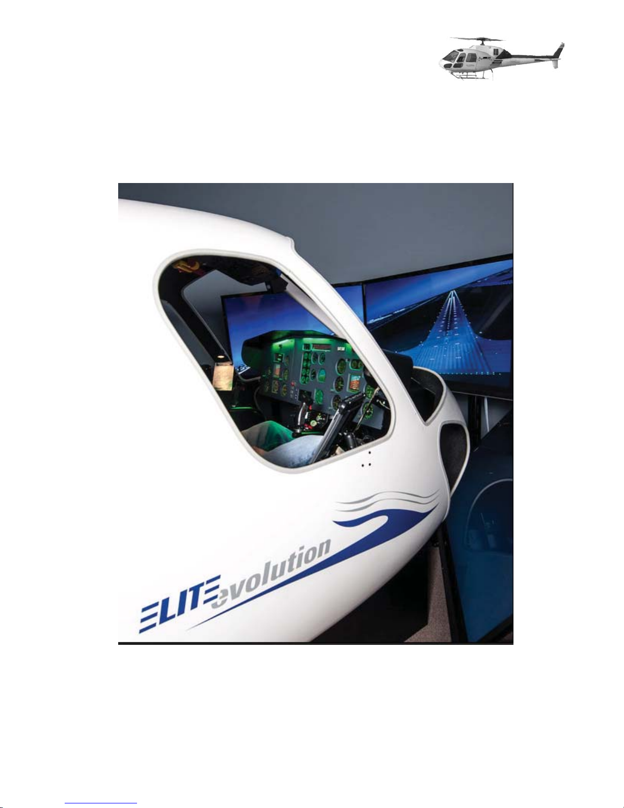
SECTION 2 FLIGHT DECK
2.1 General
The fl ight deck is designed to withstand normal loads, shocks and other conditions incidental to
normal operation, transportation and assembly. The structure is suffi ciently rigid to assure that there
is no discernible movement of the Evolution S623T helicopter due to personnel movement or control
movement within the fl ight deck.
The areas included in the simulator are from the rudder pedals to the aft of the crew member seats.
An open Instructor station may be attached to the rear of the fl ight deck.
The fl ight deck is enclosed and the front, side and chin bubble windows are provide an unob-
structed view to the visual scene.
2.1.1 Cockpit
The interior of the fl ight deck is designed according to the helicopter type specifi ed.
Non-helicopter hardware, such as switches and knobs are placed in the correct location and pro-
vide the same general action. They are in a similar appearance to those found in the actual helicopter.
2.1.2 Aircraft Parts
The Evolution S623T helicopter does not include original helicopter parts.
2.1.3 Instrument Panel Technical Realization
Three TFT monitors are used for pilot, co-pilot and engine instruments. The appearance to the
fl ight crew is similar to that in the aircraft. All instruments are displayed close to actual size. All
buttons, controls and switches are located according to above layout (Flight and engine controls
hardware).
2.1.4 Simulated Instruments
All simulated instruments are basically operational as in the actual helicopter.
Inst
rumen
t f
ace markings, including graduations, pointers, fl ags, etc. are reproduced as authentically as possible accord-
ing to the actual helicopter instruments. Instrument functionality that requires hardware components
that are not simulated are not implemented.
All switches and knobs are operational and have a comparable feel to its original counterparts. Instrument response rates are equal to those found in the helicopter.
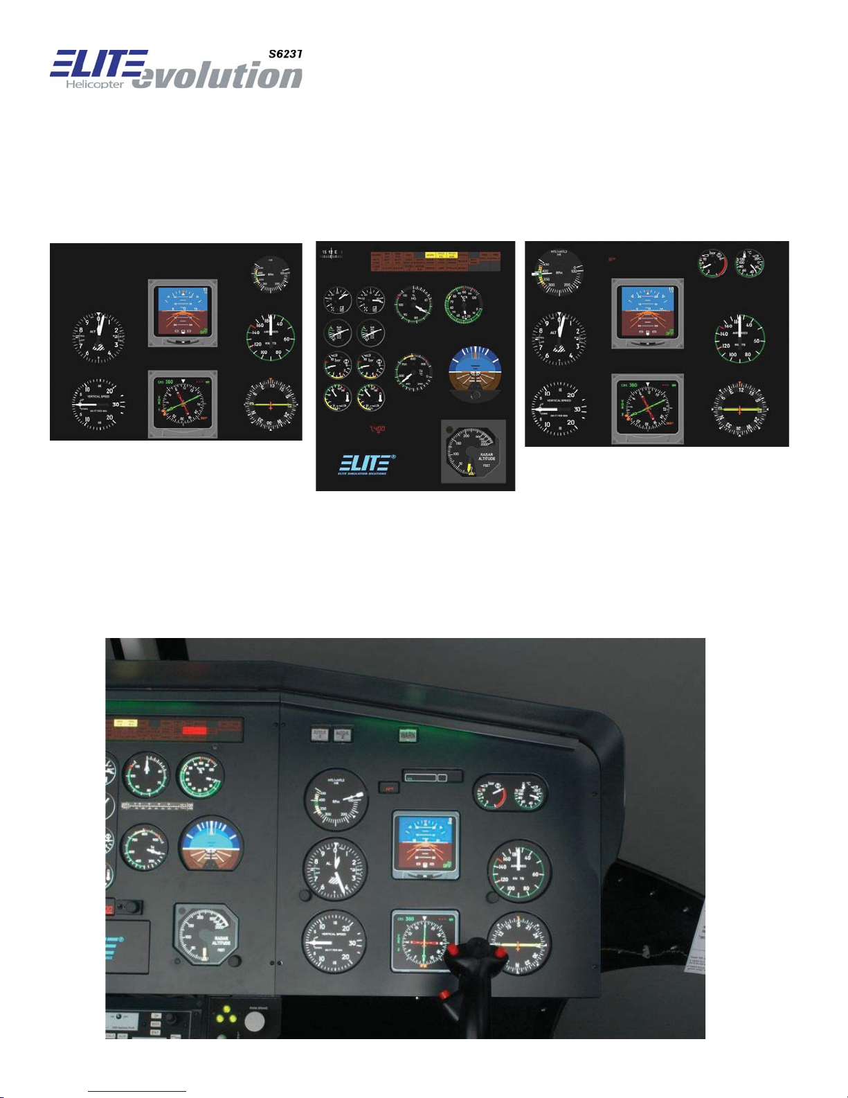
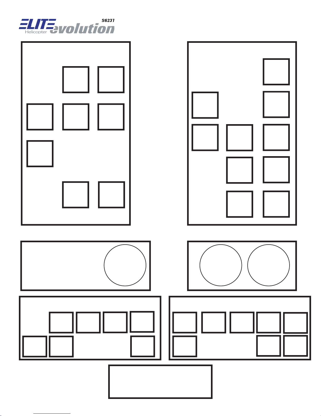
2.2 Standard Cockpit Panel Layout
2.2.1 Overview Instruments Layout
Copilot (EFIS version) Engine Pilot (EFIS version)
2.2.2 Pilot’s Main Panel

Airspeed Indicator Generic for twin engine turbine helicopter
Altitude Indicator Generic for twin engine turbine helicopter
Dual Needle RMI KNI 582
HSI or EFIS Generic or EFIS EFS 40
GSP Annunciator Panel Generic
Rotor RPM and NF1/2 Generic for twin engine turbine helicopter
Vertical Speed Indicator Generic for twin engine turbine helicopter (Instantaneous type for IFR helicop-
ters in Australia)
OAT Generic
Main Gearbox Oil Pressure Generic
Main Gearbox Oil Temperature Generic
Main Gearbox Oil Pressure Generic
Wa rning Attention Getter Switch Generic
Auto Relight 1 Switch Generic
Auto Relight 2 Switch Generic
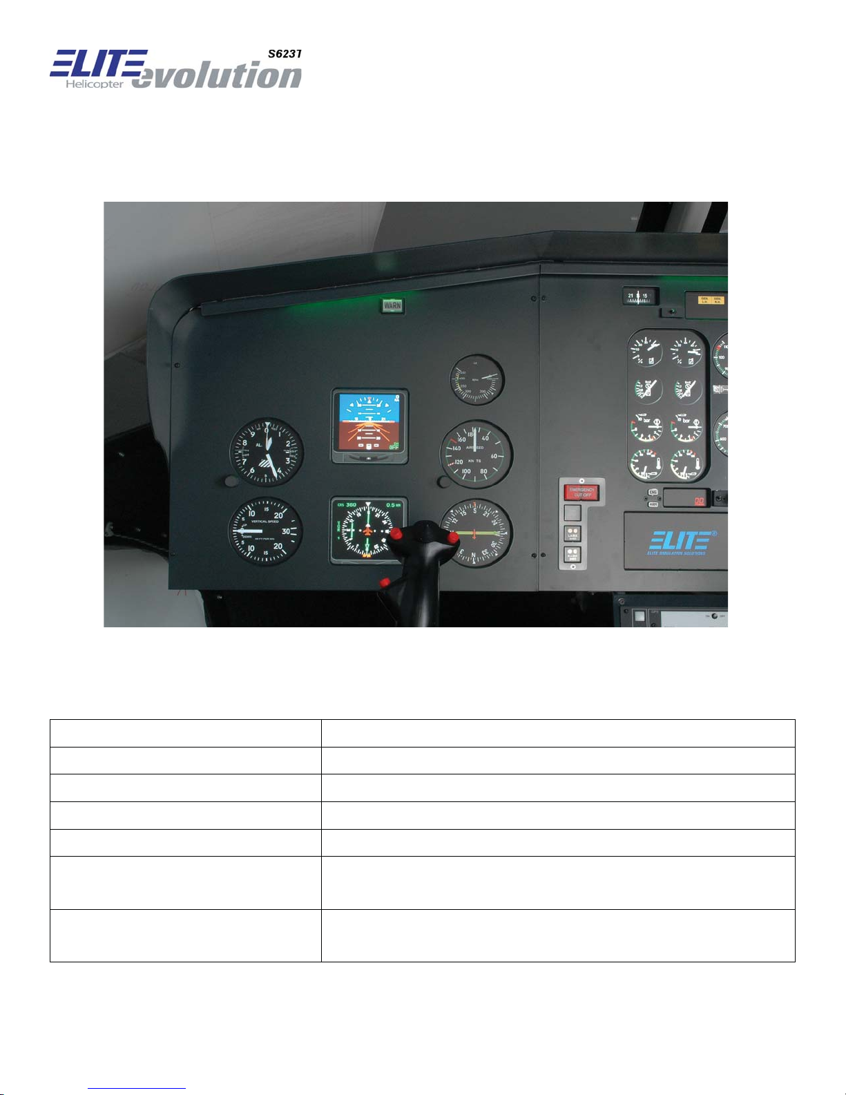
2.2.3 Co-Pilot’s Main Panel
Airspeed Indicator Generic for twin engine turbine helicopter
Altitude Indicator Generic for twin engine turbine helicopter
Dual Needle RMI KNI 582
HSI or EFIS Generic or EFIS EFS 40
Rotor RPM Generic for twin engine turbine helicopter
Vertical Speed Indicator
Wa rning Attention Getter Switch Generic
Generic for twin engine turbine helicopter
(Instantaneous type for IFR helicopters in Australia)
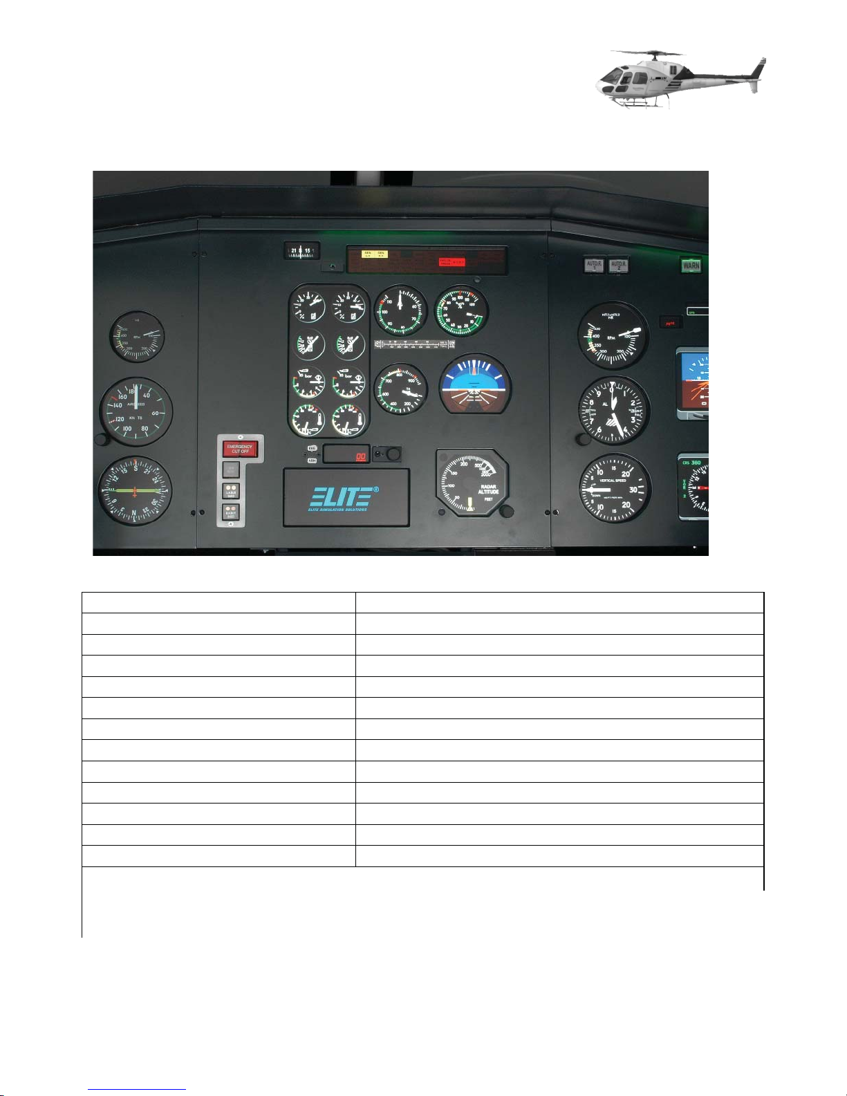
2.2.4 Engine Instrument Panel
Left engine fuel gauge Generic for twin engine turbine
Right engine fuel gauge Generic for twin engine turbine
Left engine fuel pressure gauge Generic for twin engine turbine
Right engine fuel pressure gauge Generic for twin engine turbine
Left engine oil pressure gauge Generic for twin engine turb ine
Right engine oil pressure gauge Generic for twin engine turbine
Left engine oil temp gauge Generic for twin engine turbine
Right engine oil temp gauge Generic for twin engine turbine
Left/right engine NR Generic for twin engine turbine
Left/right engine Torque Generic for twin engine turbine
Left/right engine T4 Generic for twin engine turbine
GPS GNS 430W or GNS 530W
Standby HSI Generic
Generator reset switch Generic
Annunciator panel Generic for twin engine turbine
Emergency Cut-off switch Generic
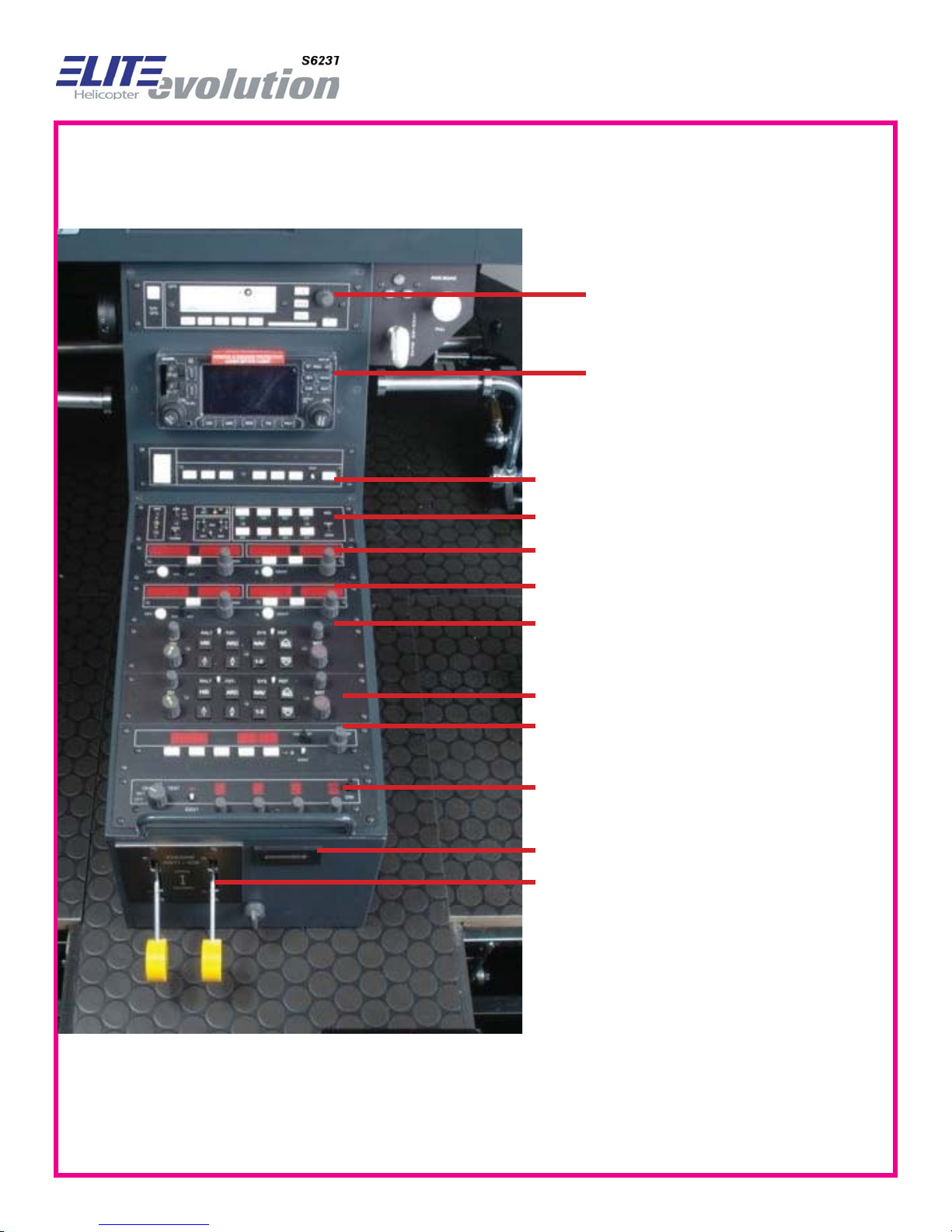
2.3 Avionics Panel / Nav Panel (various layouts & options available)
Trimble GPS 2000
Approach +
Garmin GNS 430*
(when installed NAV1
COMM1 is omitted)
autopilot KFC 150
P
Audio
NA V1 / C
anel
O
MM1 KX 165-25
NAV2 / C
EFIS EFS 40
EFIS EFS 40
O
MM2 KX 165-25
/
50
/
50
DME KN 62A
Transponder KT 70
Hobbs meter
De-ice levers
2.4 Overhead Panel
2.4.1 Implementation
The overhead panels are divided in Aft Control Panel, Fwd Control Panel and Control Quadrant. This section describes the hardware implementation of the several overhead panel elements.
2.4.2 General
All buttons are background lit. Light intensity can be controlled with OP_ACDC_3, which is implemented on the “AC-DC Gauge Selector Panel” (see chapter 2.4.5).
Exceptions are OP_FWDR_7 (BATT, Panel 3) and OP_AFTR_3 (FUEL INTERC, Panel 4). The
background light intensity of these switches are doubled if the selected function is active and thus
depends on the simulation.
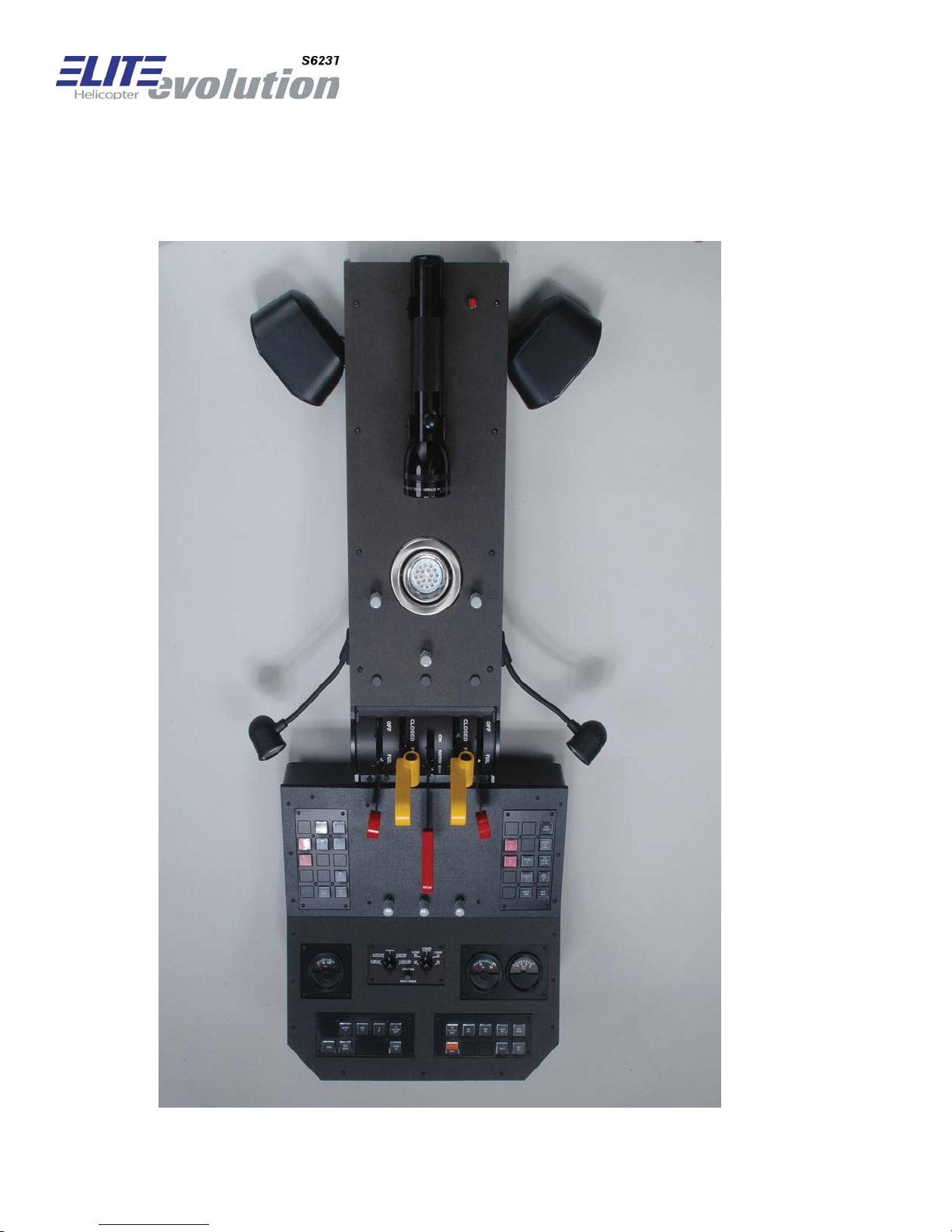
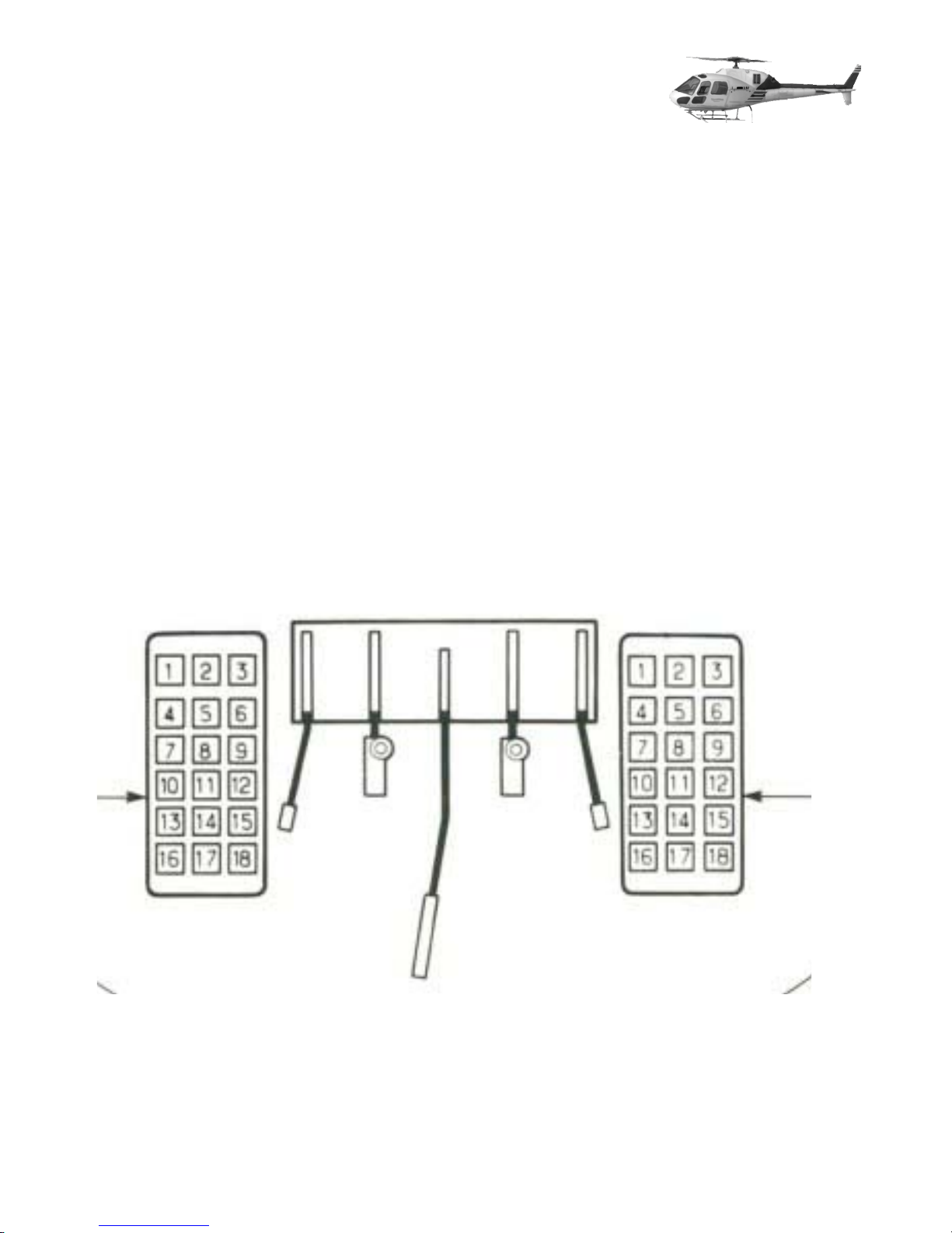
2.4.3 Aft Control Panel
Aft Control Panel is divided in left- and right-hand panel.
Aft Control Panel and Control Quadrant

2.4.3.1 Aft Control Panel, left side, Panel 1
The following switches are implemented:
Switch ID
OP_AFTL_2 Pushbutton
Typ
e
PIT
CH TRIM ACTU
Label
ATO
OP_AFTL_3 Pushbutton TRIM RELEASE
OP_AFTL_5 Pushbutton ROLL TRIM ACTU
ANK
OP_AFTL_6 Pushbutton CR
OP_AFTL_7 Pushbutton FIRE
LH EN
EXT
ATO
G
No1
LH
OP_AFTL_10 Pushbutton FIRE
EXT
No2
LH
OP_AFTL_12 Pushbutton
INST PANE
L L
T
R
R
OP_AFTL_17 Pushbutton COPLT WIPER
Pushbutton R
The following buttons are not implemented and are covered with blanks:
1,4,8,9,11,13,14,15,16,18
AD ALT
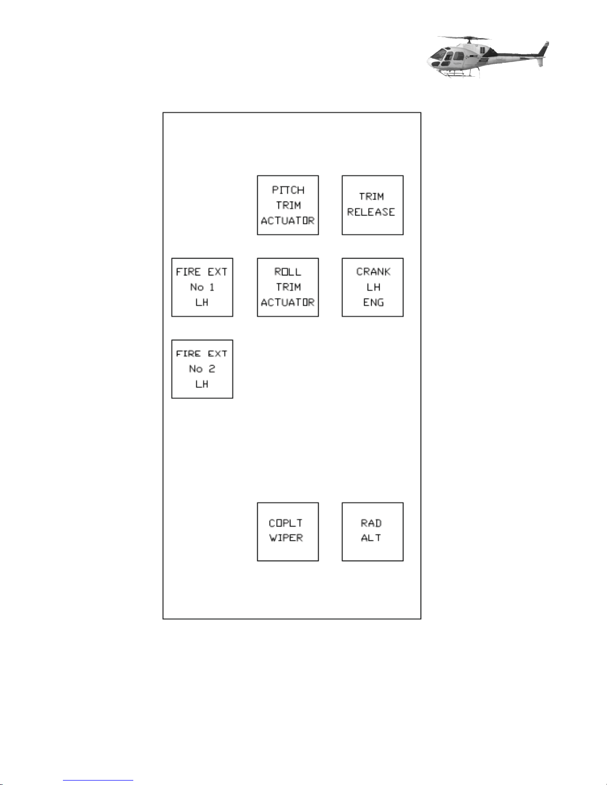
Layout Aft Left Side – Switch panel 1

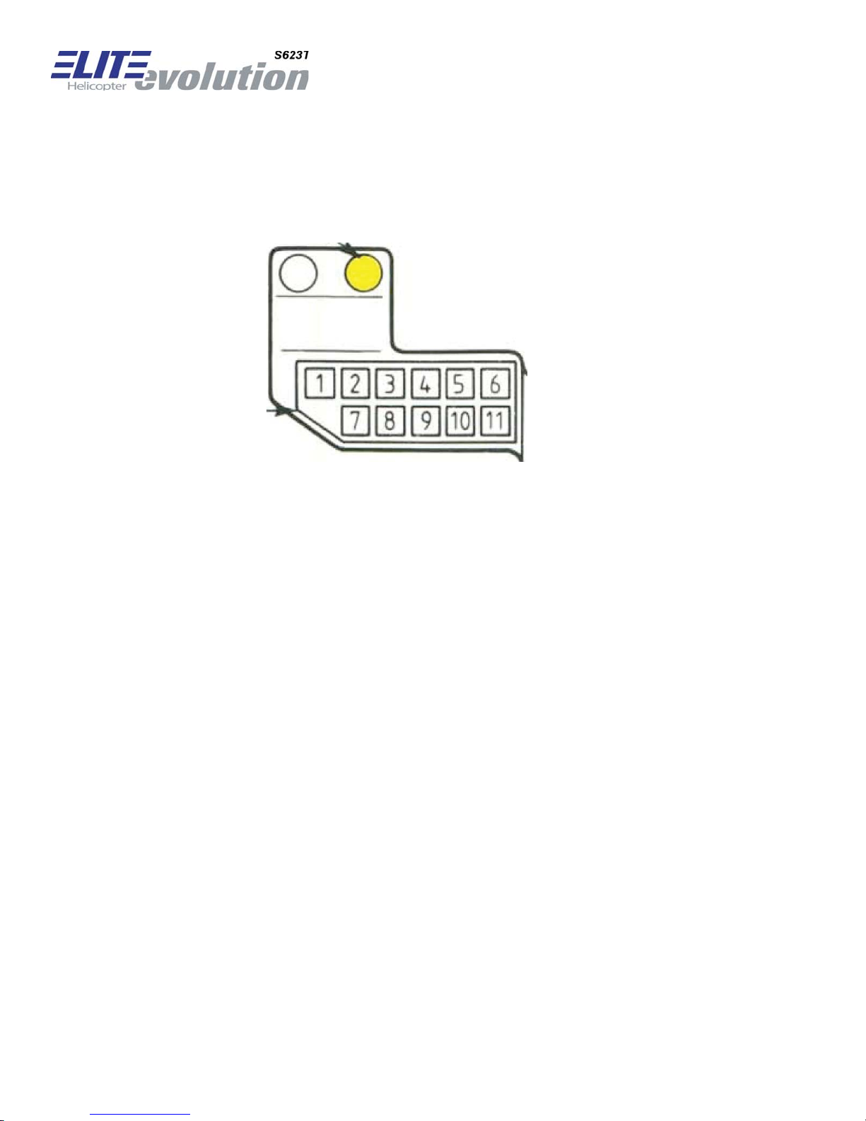
2.4.3.2 Aft Control Panel, right side, Panel 4
The following switches are implemented:
Switch ID Type Label Backgrou
nd Color
OP_AFTR_3 Pushbut-
FUEL INTERC black Double ligh
ton
OP_AFTR_6 Pushbut-
CR
RH EN
G
black
ANK
ton
OP_AFTR_7 Pushbut-
FIRE
EXT
No1
ton
RH
EXT
OP_AFTR_10 Pushbut-
FIRE
No2
ton
RH
OP_AFTR_11 Pushbut-
STROBE LT black
ton
OP_AFTR_12 Pushbut-
ton
L
TS TRANSF
LH<-RH
black
red
red
Remarks
t
intensity if
valve is opened
OP_AFTR_14 Pushbut-
ton
OP_AFTR_15 Pushbut-
ton
OP_AFTR_17 Pushbut-
ton
OP_AFTR_18 Pushbut-
ton
The following buttons are not implemented and are covered with blanks: 1,2,4,5,8,9,13,16
CONSOLE LT black
INST PANE
WDS.
A
RM
W.
L L
T
black
black
PITOT HEAT black
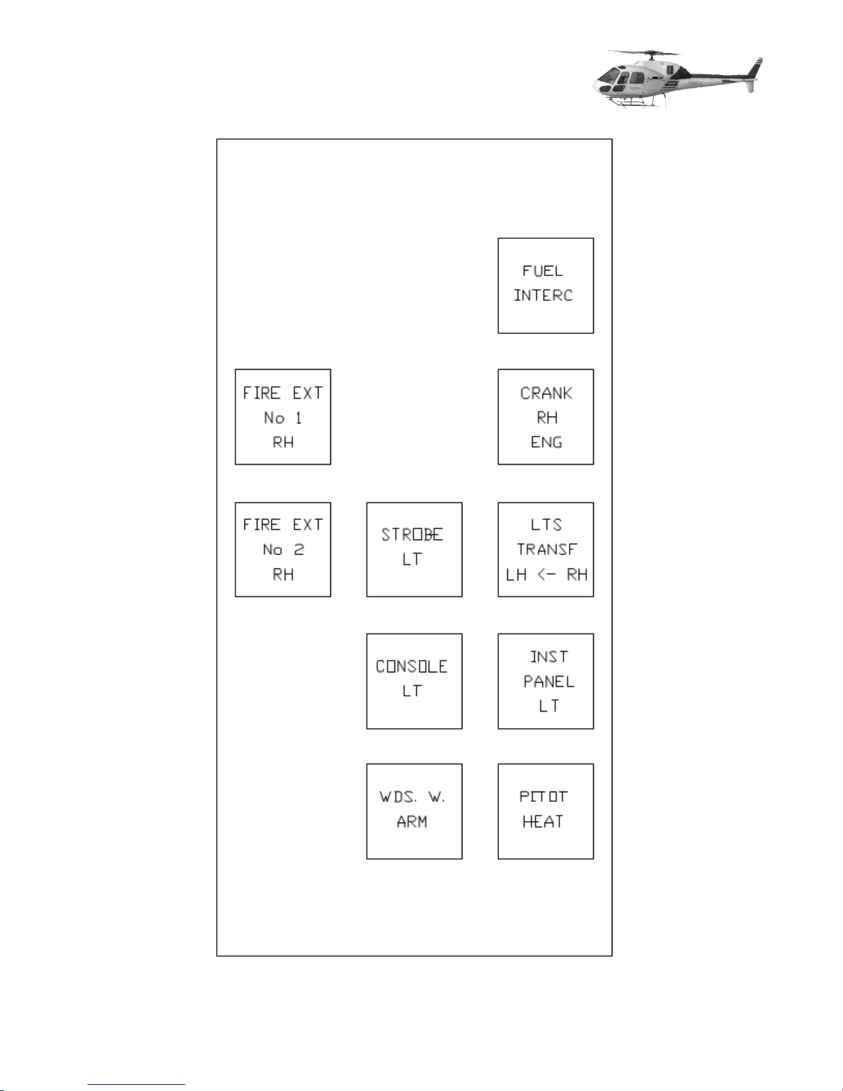
Layout, Aft Right Side – Switch panel 4
2.4.4 Fwd Control Panel
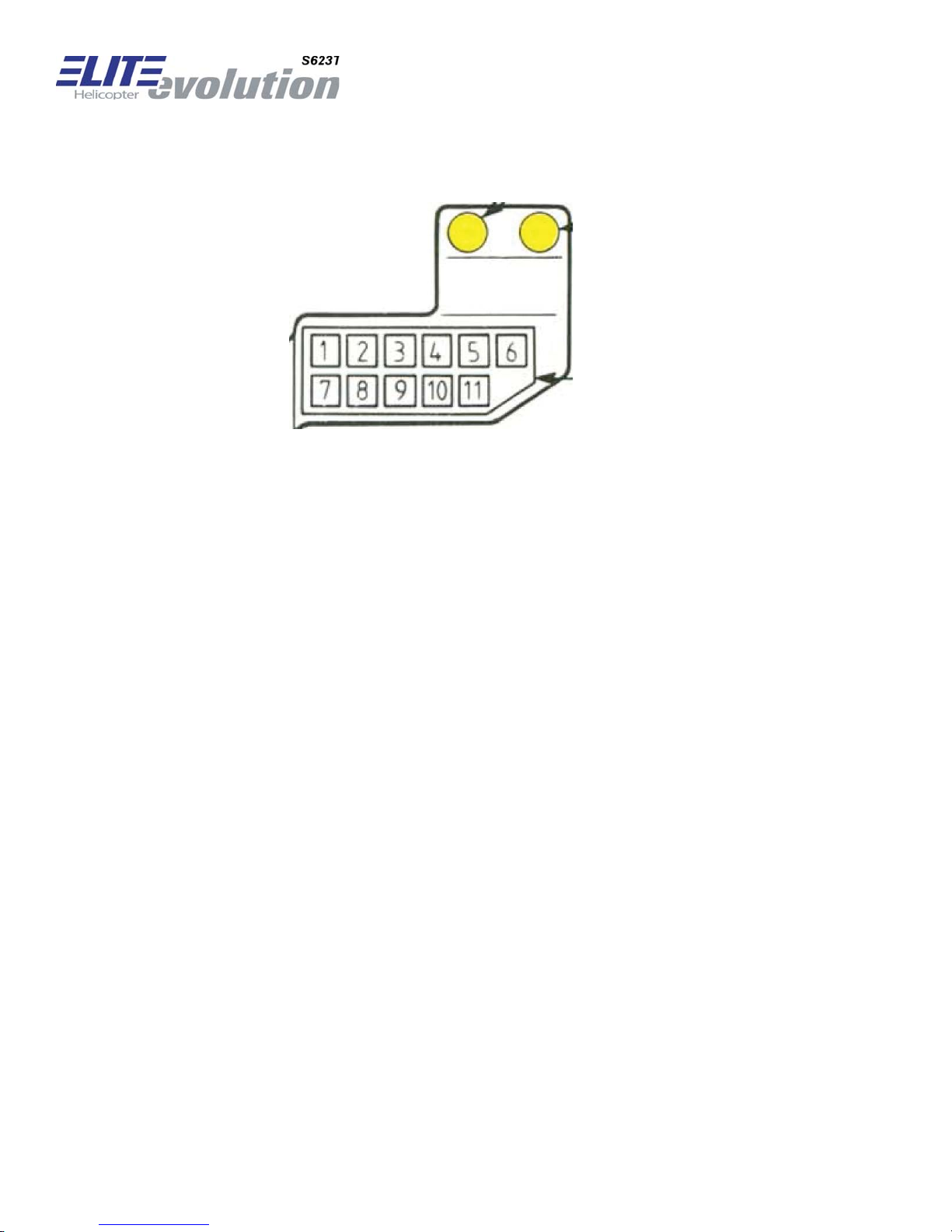
2.4.4.1 Fwd Control Panel, left side, Panel 2
Fwd Control Panel, left side, original layout
Switch ID
Typ
e
Label
Backgr
C
olo
ound
OP_FWDL_3 Pushbutton INVERT LH black
GE
OP_FWDL_4 Pushbutton
OP_FWDL_5 Pushbutton LH
OP_FWDL_6 Pushbutton LH
N LH black
B.P.
EXT PWR BATT
black
black
OP_FWDL_7 Pushbutton HORN black
OP_FWDL_8 Momentary TEST SERVO black
OP_FWDL_9 Pushbutton O ptional: Co
G
yro
P
i
black
OP_FWDL_10 Pushbutton Optional: CoPi ADI black
r
OP_FWDL_11 Pushbutton STDBY AH black
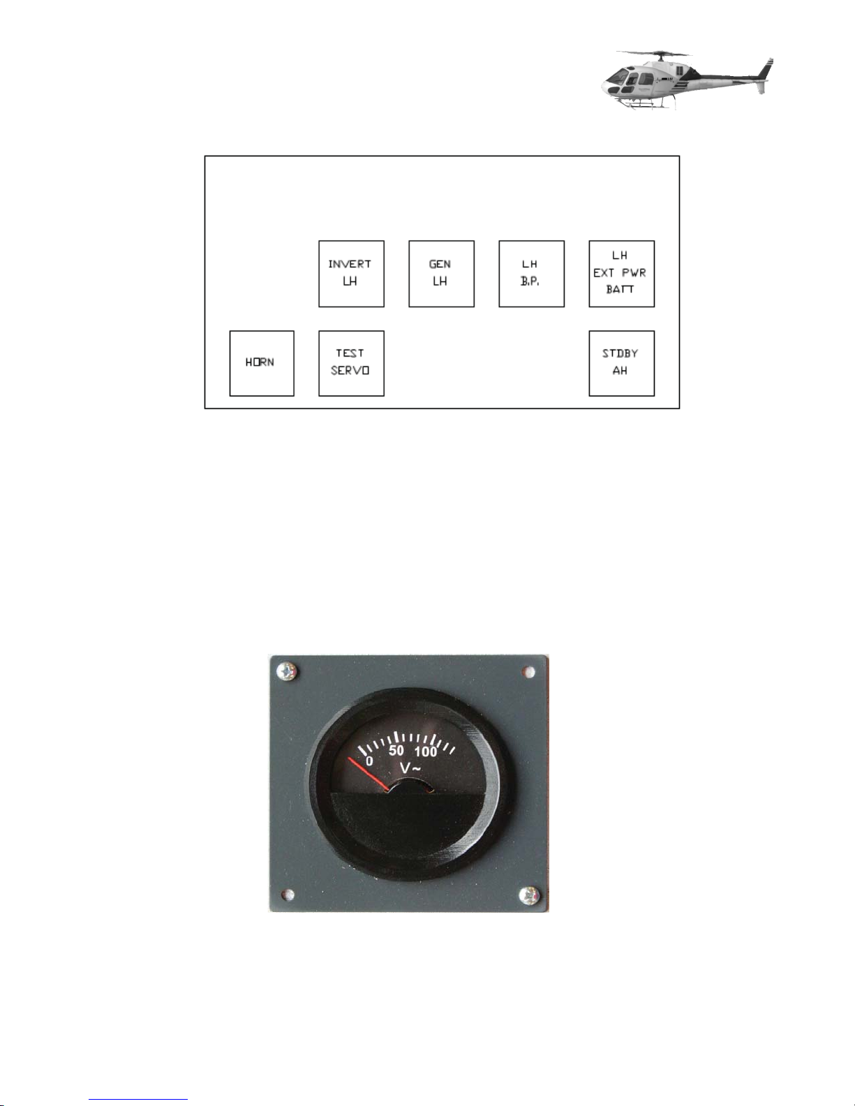
Layout, FWD Left Side – Switch panel 2
The following buttons are not implemented and are covered with blanks: 1,2
Gauge ID
In addition the following gauge has been implemented
Typ
e
:
OP_FWDL_G1 Pointer gauge AC Voltmeter
2.4.4.2 Fwd Control Panel, right side, Panel 3
Fwd Control Panel, right side, original layout
The following switches are implemented, options are marked:
Switch ID
OP_FWDR_1 Pushbutton RH
Typ
e Label Backgr
EXT PW
R
C
olo
black
ound
r
Remarks
BATT
OP_FWDR_2 Pushbutton RH
OP_FWDR_3 Pushbutton
GE
B.P.
N RH black
black
OP_FWDR_4 Pushbutton INVERT RH black
OP_FWDR_6 Momentary TEST AU-
black
TOR
OP_FWDR_7 Pushbutton BATT black Double light in-
tensity if valve
is opened
P
ilo
OP_FWDR_8 Pushbutton Optional:
t
OP_FWDR_9 Pushbutton Optional: Pilo
OP_FWDR_10 Pushbutton POS LT black
OP_FWDR_11 Pushbutton
A
D
I
G
yro
ANTI CO
t
L black
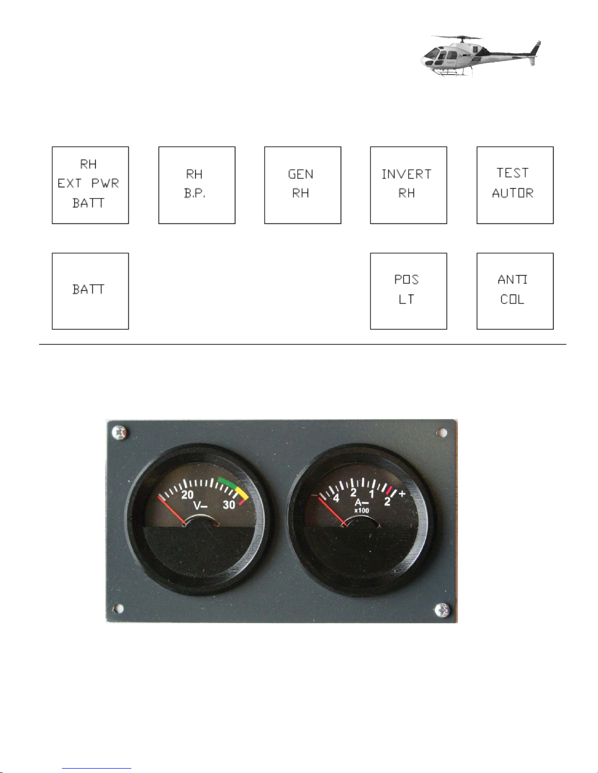
Layout, FWD Right Side – Switch panel 3
The following buttons are not implemented and might be covered with blinds: 5,6
In addition the following gauges have to be implemented:
Fwd Control, right side gauges, OP_FWDR_G1 and OP_FWDR_G2
Gauge ID
OP_FWDR_G1 Pointer gauge DC Voltmeter
OP_FWDR_G2 Pointer gauge Ammeter
Typ
e
PITCH
TRIM
ACTUATOR
TRIM
RELEASE
TRIM
RELEASE
FIRE EXT
No 1
LH
FIRE EXT
No 2
LH
ROLL
TRIM
ACTUATOR
COPILOT
WIPER
CRANK
LH
ENGINE
RAD
ALT
FIRE EXT
No 1
RH
FIRE EXT
No 2
RH
STROBE
LT
CONSOLE
LT
COPILOT
WIPER
PITCH
TRIM
ACTUATOR
FIRE EXT
No 1
LH
RAD
ALT
FIRE EXT
No 2
LH
INVERT
LH
HORN
TEST
SERVO
GEN
LH
OP_FW DL
_G1
LH
BP
EXT PWR
STDBY
LH
BATT
AH
AC - DC
SELECTOR PANEL
RH
EXT PWR
BATT
BATT
OP_FW DL
_G1
RH
BP
GEN
RH
OP_FW DL
_G1
INVERT
RH
POS
LT
TEST
AUTOR
ANTI
COL
 Loading...