

Page 1
AHD CCTV TEST MONITOR
USER MANUAL
www.espuk.com
Page 2
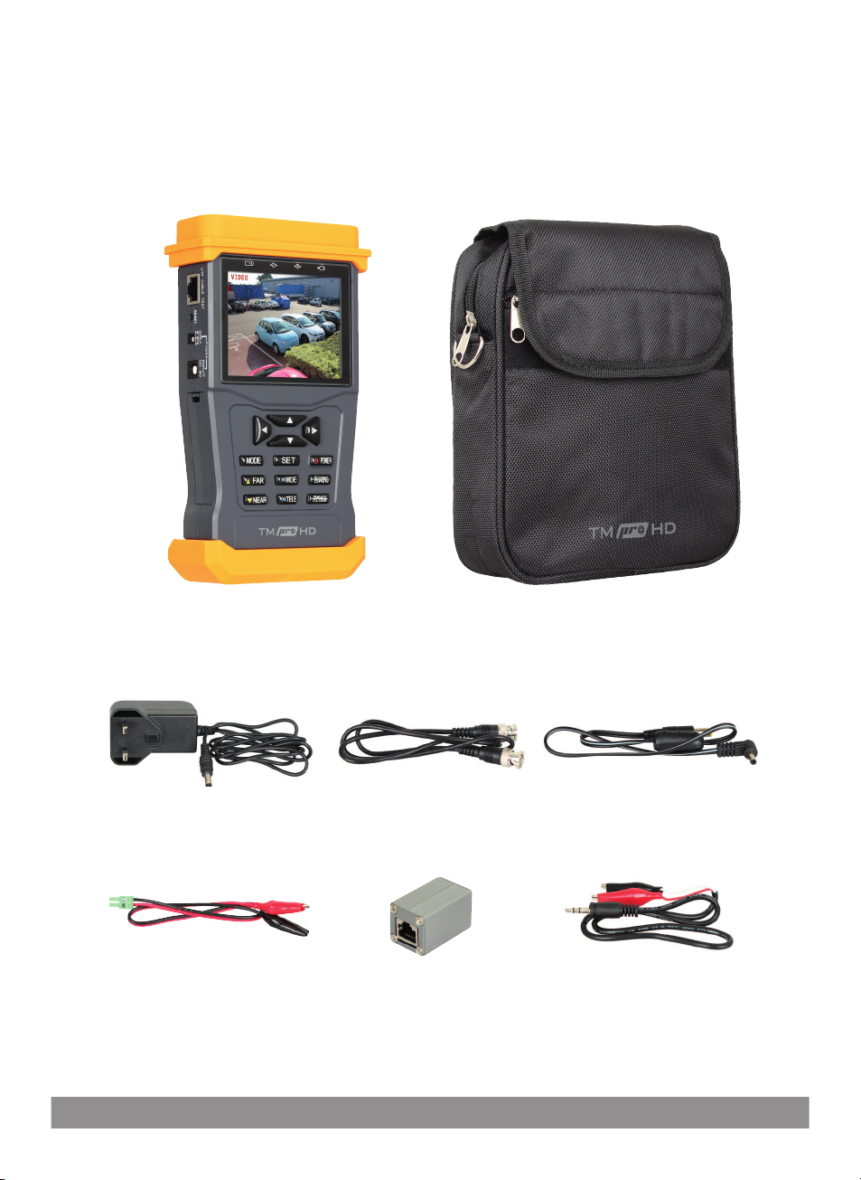
TMProHD Contents
TMProHD AHD CCTV Test Monitor
Power Supply Charger
for test monitor
RS485 Connector patch lead
for testing PTZ controls
2
Case for test monitor and accessories
BNC TO BNC patch lead for use
with viewing video signals
UTP cable tester
module for use with
UTP cable test function
12VDC 1Amp Output patch
lead for camera power
Audio jack patch lead
Page 3
TMProHD - Getting Started
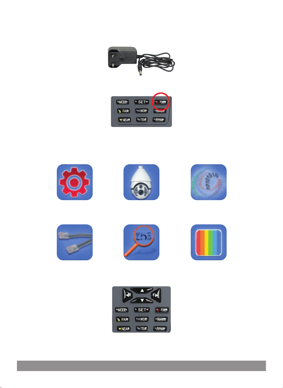
Connect the provided power supply to the power input
connection on TMPROHD and charge for 4 hours before first use
After charging, press and hold the power
button to switch on the test monitor
TMProHD Menu options
System Setup
General monitor options
PTZ control options
UTP Cable Test
Displays cable test results
Use the arrows on the test monitor to navigate the menu,
press ENTER to select a menu and SET to adjust the options.
Video and PTZ Control
View video input and
PTZ control options
Address Search
Searches PTZ address for
identification
Press the RETURN key to escape a menu.
485 Data Test
Displays RS485 data
sent from control devices
Colour Bar Generator
For testing monitors
use video output
3
Page 4
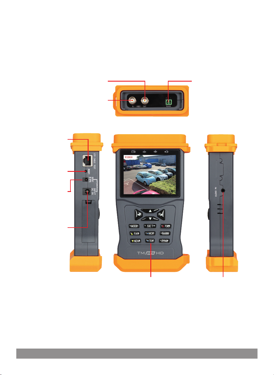
TMProHD Connections
For use with BNC patch lead
Provides monitor output
For use with BNC patch lead
Provides input for video signal
UTP Test Port
For use with UTP
test module
Connection for
testing cable
Reset test monitor
(hold 3 Sec.)
12vDC 1Amp Output
For use with
12vDC patch lead
Provides power
supply to camera
Charger Input for
Test Monitor
Video Output
Video Input
RS485 Connector
For use with RS485
patch lead
Provides connection
for RS485 devices
(Such as PTZ controls)
Tester Monitor Navigation/
PTZ Control Buttons
4
Audio Input
For use with audio
jack patch lead
Page 5
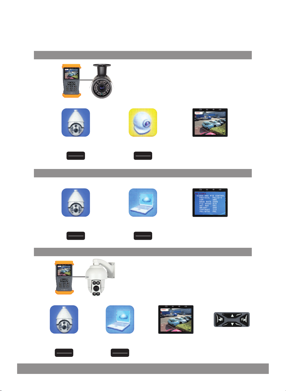
TMProHD Basic Functions
TO VIEW A CAMERA IMAGE
Using the BNC patch lead connect ‘Video-In’
on the test monitor to the Camera output
Using the12vDC patch lead connect ‘Power Out’
of the test monitor to camera power input
STEP 1 STEP 2 STEP 3
Select VIDEO AND PTZ CONTROL
and press
Enter
OPEN
Select VIDEO
and press
Enter
OPEN
The image will be visible
SETTING PARAMETERS FOR PTZ CONTROL
STEP 1
Select VIDEO AND PTZ CONTROL
and press
Enter
OPEN
STEP 2 STEP 3
Select SET
and press
Enter
OPEN
Enter the required
PTZ configuration
TO VIEW IMAGE AND CONTROL PTZ CAMERA
Using the BNC patch lead connect ‘Video-In’
on the test monitor to the PTZ camera output
Use the RS485 patch lead to connect from the test
monitor’s RS485 connection to the PTZ’s control leads
Ensure that the PTZ is suitably powered
STEP 1 STEP 2 STEP 3 STEP 4
Select VIDEO AND PTZ CONTROL
and press
Enter
OPEN
Select SET
and press
Enter
OPEN
The image will be visible
Use test monitor
navigation buttons
to control PTZ
5
Page 6
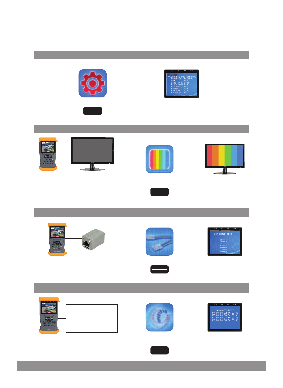
TMProHD Additional Functions
SYSTEM SETUP
STEP 1
Select SYSTEM SETUP and press General test monitor options can be adjusted
Enter
OPEN
COLOUR BAR GENERATOR FOR TESTING MONITOR
Using the BNC patch lead connect
‘Video-Out’ of the test monitor to the
monitor input connection
Ensure monitor is suitably powered
in this menu alongsidePTZ control setup
STEP 1 STEP 2
Select COLOUR BAR GENERATOR
and press
Enter
OPEN
UTP CABLE TESTER
STEP 1 STEP 2
STEP 2
View colour bar
generator results
Connect cable from the test monitor’s
UTP port to UTP module
Using the RS485 patch
lead connect RS485
out to the RS485
device control leads
6
Select UTP TEST and press View test results
Enter
OPEN
RS485 DATA CHECK
STEP 1 STEP 2
Select RS485 DATA CHECK
and press
Enter
OPEN
Control the RS485 device
to obtain data test results
Page 7
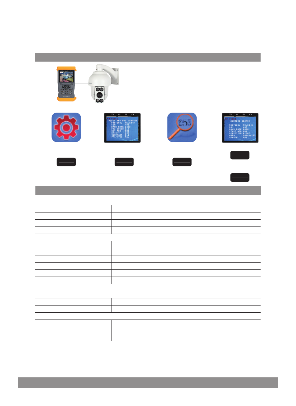
PTZ ADDRESS SEARCH
Use the RS485 patch lead to connect from the test
monitor’s RS485 connection to the PTZ’s control leads
Ensure that the PTZ is suitably powered
STEP 1STEP 2STEP 3STEP 4
Select SYSTEM SETUP
and press
Enter
OPEN
Adjust PTZ control
setup and press
Enter
OPEN
Select ADDRESS SEARCH
and press
Enter
OPEN
Press
SET
then search for
address by pressing
Enter
OPEN
TMPROHD SPECIFICATION
VIDEO SIGNAL
Signal Mode NTSC/PAL automatically suitable
Display 3.5 inch LTPS LCD screen, 960x240 resolution
Video Input 1 Channel BNC
Video Output 1 Channel BNC
PTZ CONTROL
Communication Interface Support RS485 bus
Communication Protocol Compatible Pelco D / Pelco P, special protocols could be customized
Power Output DC12V 1A power output for camera
Audio Test Input 1 ch audio signals , test audio
UTP Cable Test Test UTP Cable connection state and display on the screen
RS485 Data Test 485 data analysis ,displayed on the screen in hexadecimal
Colour barcode generator
POWER
External power DC9V/2A
Battery 2000mAH
WORKING ENVIRONMENT
Working Temperature -30 to +70
Working Humidity 30% to 90%
Dimensions 105 x 44 x 188mm
WARNING
This product is not waterproof.
Please avoid exposing product to rain, moisture or any liquids as this may cause a malfunction.
7
Page 8

Elite Security Products
Unit 7, Target Park, Shawbank Rd
Lakeside, Redditch B98 8YN
Telephone: 01527 51 51 50
Fax: 01527 51 51 43
email: [email protected]
www.espuk.com
 Loading...