

Page 1
Page 2
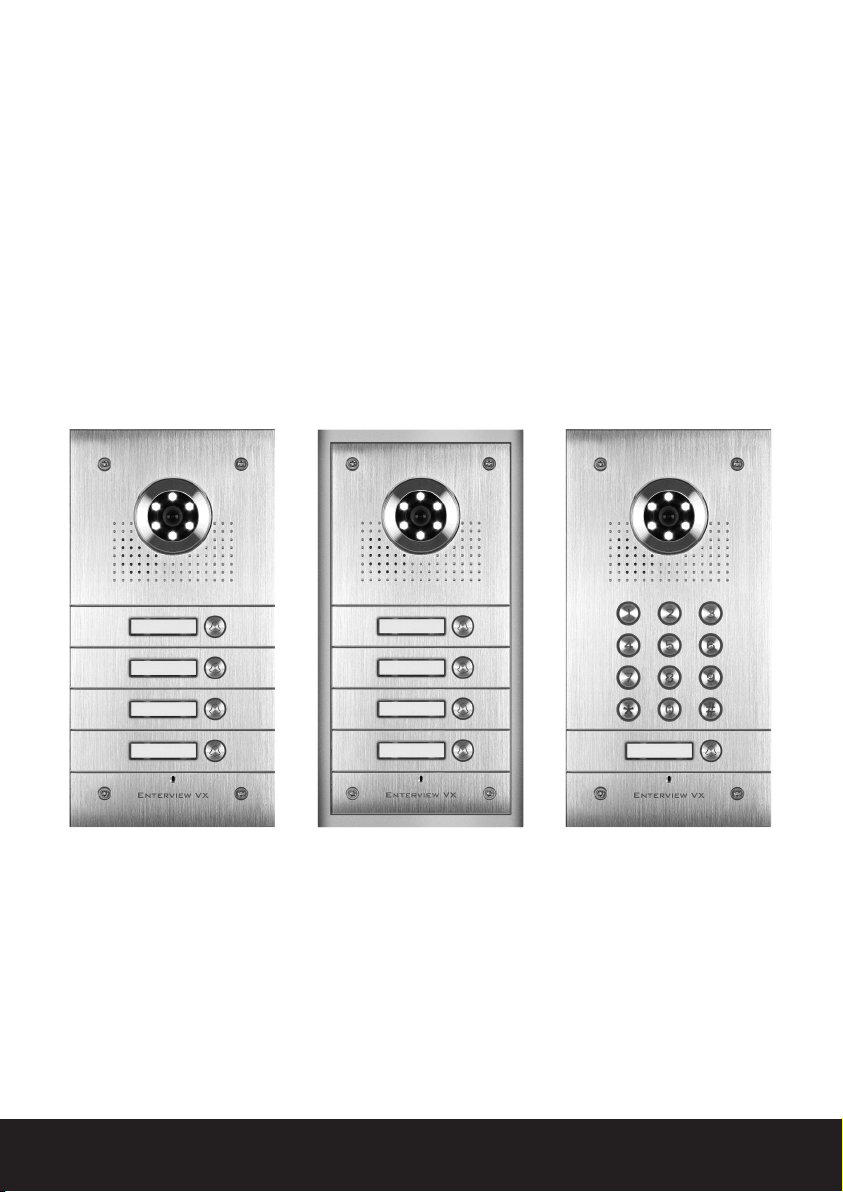
Table of contents
Planning and installing the Enterview VX . . . . . . . . . . . . . . . . . . . . . . . . . . . . 3
Wiring Diagram . . . . . . . . . . . . . . . . . . . . . . . . . . . . . . . . . . . . . . . . . . . . . . . . . . . . . 5
Fitting the external call station . . . . . . . . . . . . . . . . . . . . . . . . . . . . . . . . . . . . . 6
Fitting and wiring the handset . . . . . . . . . . . . . . . . . . . . . . . . . . . . . . . . . . . . . . 7
Programming the Enterview VX keypad . . . . . . . . . . . . . . . . . . . . . . . . . . . . . . 9
Optional accessories for Enterview VX . . . . . . . . . . . . . . . . . . . . . . . . . . . . . 11
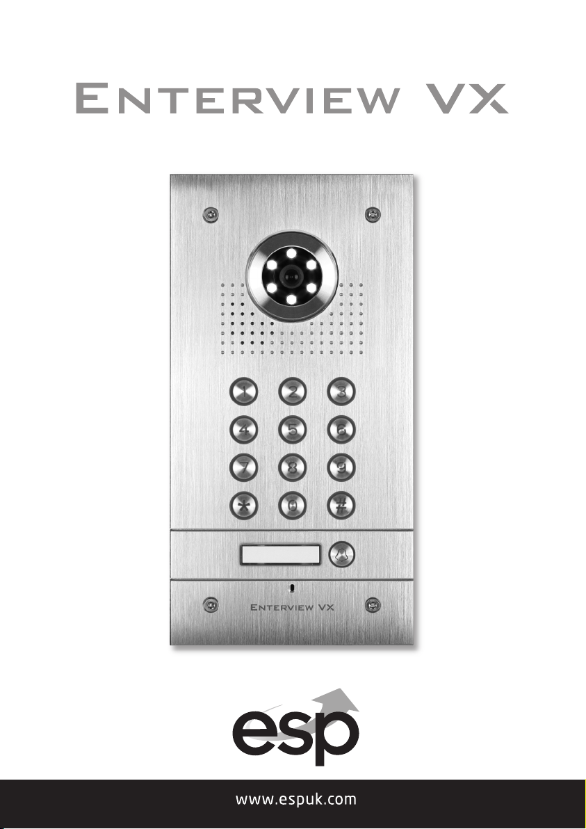
EVVX1F
1 button flush mount video
door station
EVVX2F
2 button flush mount video
door station
EVVX3F
3 button flush mount video
door station
EVVX4F
4 button flush mount video
door station
2
EVVX1S
1 button surface mount
video door station
EVVX2S
2 button surface mount
video door station
EVVX3S
3 button surface mount
video door station
EVVX4S
4 button surface mount
video door station
EVVX1KPF
1 button flush mount video
door station with keypad
EVVX2KPF
2 button flush mount video
door station with keypad
EVVX1KPS
1 button surface mount video
door station with keypad
EVVX2KPS
2 button surface mount video
door station with keypad
Page 3

Planning and installing the Enterview VX
Planning your MX Door Entry System
External call station
How many Entry Doors (Front or/and Rear)
Audio only or with Video
Monochrome/ colour
Integral Keypad
Mounting: flush or surface.
External Call buttons (one per dwelling)
Keypad entry control
Combined timed lock and outdoor call station power supply (EVBPS)
Note: The maximum cable distance from the external panel to each internal handset
is 100 meters using CAT5e cable. The maximum distance per supplied power
supply to each handset is 10 meters using 2 pairs of CAT5e cable.
Equipment required
External call station (one required per door)
Maximum of 4 call buttons
External call station power supply DC 12 volts (EVBPS) (one required per door)
Handset EV5H/EV5HF (minimum of one per external call button)
Electric lock magnetic (ML250)/Yale type (ENTERD)
CAT5e cable minimum 4 cores (see Note above regarding cable distances)
Push to exit button (one required per door if magnetic lock used)
Emergency break glass (One required per door if magnetic lock used and the door
is deemed and emergency exit)
Handsets
Audio/video handsets: a minimum of one per external call button/ a maximum of
4 video door entry handsets and 2 audio only handsets.
Monochrome or colour picture
Each handset requires the supplied power supply.
Door Gear
Power supply with timed output (EVBPS)
Magnetic lock or Yale type lock
Push to exit button and emergency break glass (only needed when magnetic lock
fitted and to an emergency exit door)
3
Page 4

Basic cabling
240 VAC mains feed to external door and lock control power supply (EVBPS)
240 VAC mains feed to each handset (via transformer- supplied)
4 core from each external call station (front/rear) to its own power supply (EVBPS)
CAT5e from each external call station (front/rear) to each handset
4 core from push to exit button to EVBPS (power supply)
4 core from lock to EVBPS (power supply)
4 core from EVBPS (power supply) to emergency break glass (if fitted)
2 pairs of CAT5e from supplied power supply to each handset
Note: The maximum cable distance from the external panel to each internal handset
is 100 meters using CAT5e cable. The maximum distance per supplied power
supply to each handset is 10 meters using 2 pairs of CAT5e cable.
4
Page 5
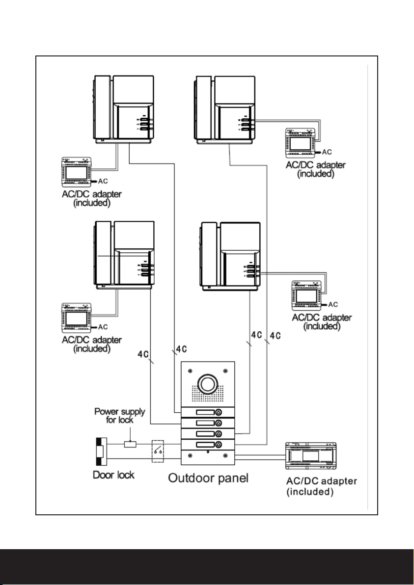
Wiring diagram
Fig. 1
5
Page 6
Fitting the external call station
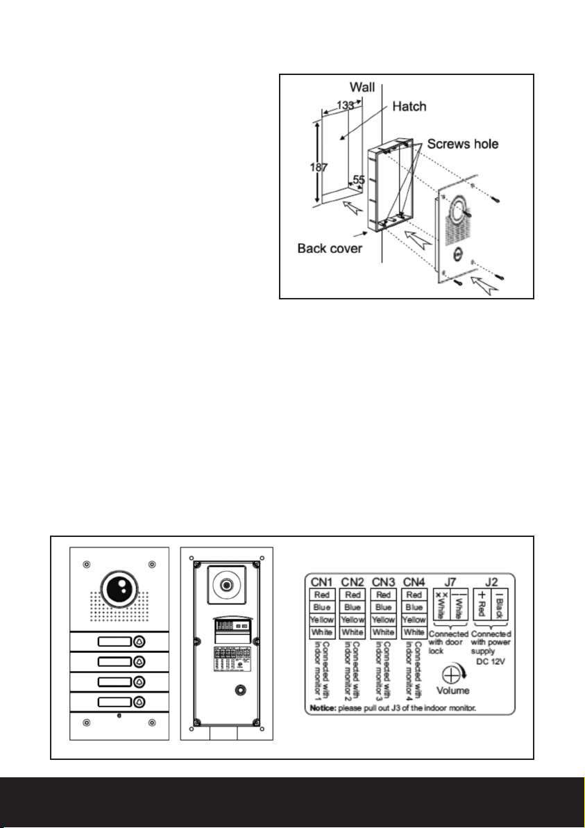
Select a location close to the
door to be controlled
Recommended mounting height
1.45 meters (camera lens)
Secure back plate to the wall
paying attention to the upward
facing arrow located on the
back plate
Feed cables from each
apartment and the power
supply through the cable entry
hole, the entry hole will need to
be knocked out.
Fig. 2
Wiring the external call station
Each call button will have its own brown 4 core connector (supplied) consisting of
red, blue, yellow and white cores.
The 4 colours that are connected to the brown connector are to be connected to
the corresponding 4 core cable going to each of the apartments.
The connection can be completed by means of soldering, crimping or by use of
screw connectors.
To power the camera, keypad and call station a 12 volt DC feed is required. To do
this a white two pin plug consisting of red and black cores supplied should be
connected to the corresponding cable going to the EVBPS power supply.
The two single black cables on the external call station are for the lock release.
These are volt free and are normally open going closed. These contacts will
change state on the lock release command. The two black cables need to be
connected the EVBPS ‘p.b’ terminal
FLUSH MOUNTING
Fig. 3
6
Page 7
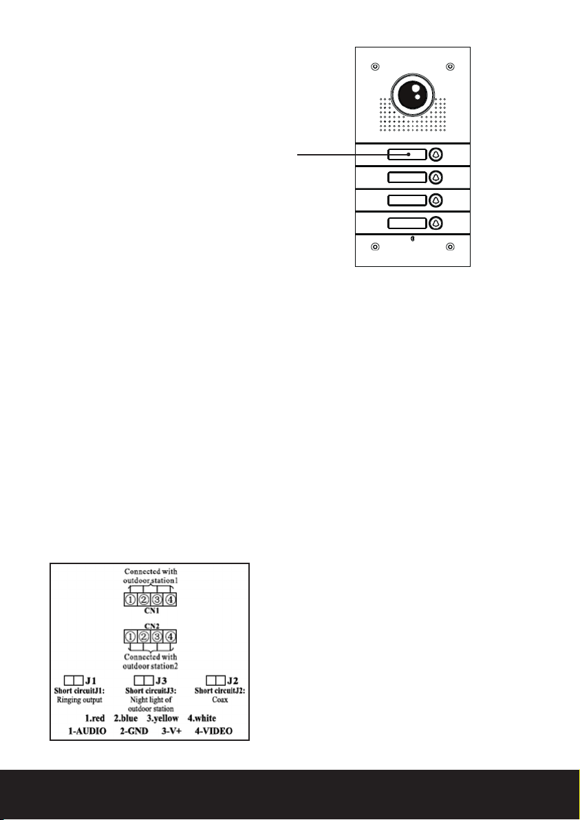
Removing name tag
To remove name tag:
1) Push in name tag on the left-hand side
2) Slide name tag from right to left
Fitting and wiring the handset
On all types of handsets fitted to a EVVX system please remove the jumper labeled
J3. This can be found next to the connecting plugs on the rear.
Locate the metal back plate and observe the arrow and the word up.
Fit mounting plate to the selected location, recommended mounting height 1.45m
Feed the cable from the local transformer and the external call button though the
center opening
Connect the corresponding cores from the external call button cable to the brown
plug (supplied) consisting of red, blue, yellow and white cores.
Once connected, fit the brown plug into the rear of the handset socket CN1 for call
station one and CN2 for external call station two.
Connect the corresponding cores from the transformer to the white plug (supplied)
consisting of red and black cores.
Once connected, fit the white plug into the rear of the handset socket marked 5 (+)
and 6
Fig. 4
Note: J1 and J2 are not used. Remove J3
on all handsets for multiway capability.
7
Page 8
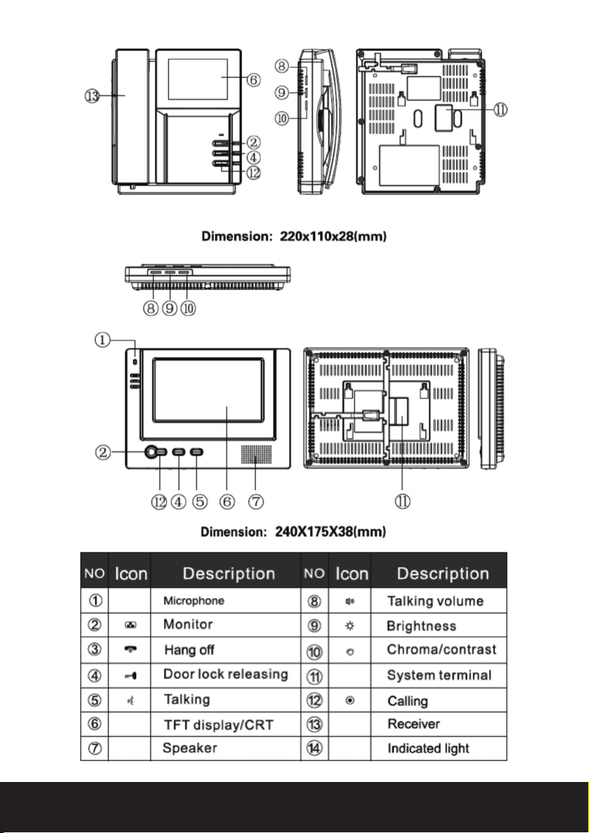
Fig. 5
Fig. 6
8
Page 9
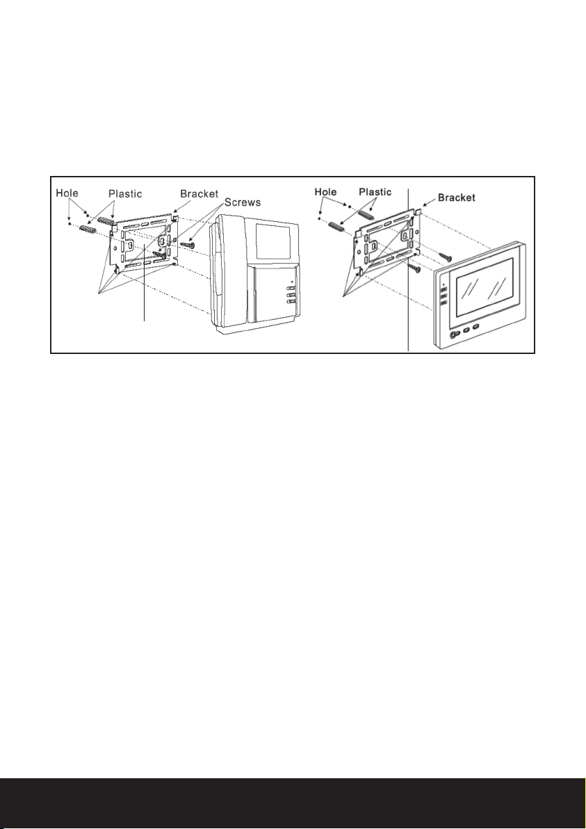
Fitting the handset to the bracket
Locate the 4 lugs on the metal back plate, one located on each corner see Fig. 7,
these lugs must fit into the recesses on the rear of the hand set.
Place the handset over the metal back plate keeping the cables flat and out of
the way of the lugs.
Slide the hand set down into position engaging the 4 lugs on the back plate into
the recesses of the hand set.
Fig. 7
Lugs
Item 1
Lugs
Programming the Enterview VX keypad
To enter programming mode press the star key followed by the 4 digit programing
pin number (the factory default programming code:1234).
Adding User Codes
Enter programming mode.
Enter the location 01 to 41.
(01 to 30 are standard code locations, 31-40 are the latching code locations). If a
series of bleeps are heard at this point this confirms a code is stored at this
location.
Enter the desired 4 digit user code.
When the new pin number has been accepted a 2 second confirmation tone will
be heard and the code lock retunes immediately to the programming mode base
level.
A long continuous tone means this pin number is in use on the system already
and cannot be used, re-enter a different location number.
Press the * key to exit programming mode.
Deleting user codes
Enter programming mode.
Enter the desired location (01 to 40 to be deleted) if a series of bleeps are heard
at this point then the location has a code stored, you may however proceed as
this is only a warning tone.
9
Page 10

Press the # key to delete the code from the location, a 2 second confirmation
tone will be heard.
Return to the beginning to delete more codes or press the * key to exit
programming mode.
Deleting user codes from an unknown location
Enter programming mode.
Press the # key
Enter the 4 digit user code to search and delete, a 2 second confirmation tone
will be heard.
Press the * key to exit programming mode.
Deleting all settings
This function should only be used in extreme circumstance as all user codes will be
deleted.
Enter programming mode.
Press the # key once.
Press the # key a further eight times to delete all information the LED will turn
off and a tone will be heard to indicate that the delete process is taking place.
You must enter all
9#s to complete the delete all command.
Note: this does restore factory settings of the lock release time of 5 seconds.
Setting the lock time
Factory default door open time is set at 05 seconds.
Enter programming mode.
Enter 00 (this selects the unlock time location).
Enter the desired lock/relay operation time in a two digit format (01 to 99
seconds).
The keypad will return to the programming mode base level.
Press the * key to exit programming mode.
10
Changing the programming code
Factory default pin 1234.
Power down the outdoor station.
Press and hold the star key.
Keep pressing the star key and power back up
A continuous tone will be heard for 5 seconds .
Release the star key wait for 5 seconds .
Enter your new 4 digit programming code you should hear the acceptance bleep
and the indication light will go out.
Page 11
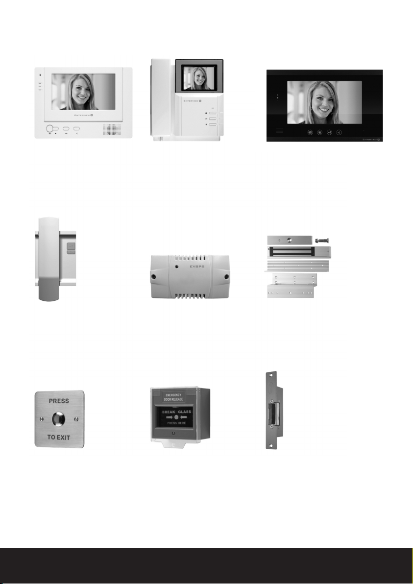
Optional accessories for Enterview VX
EVH5C-HF – Hands Free Colour
Handset
■ High resolution colour 7” monitor
■ Door release button
■ Up to 3 additionalhandsets
per system
EVH5AO – Audio only handset
■ Clear high quality audio
■ Door release button
■ Up to two per system
EVH5C – Colour Handset
■ High resolution colour 4” monitor
■ Door release button
■ Up to 3 additional handsets
per system
EVBPS - Boxed power supply
for use with lock release
■ 100-240vAC, 50/60Hz input
■ 1.5A /12vDC output (NO/NC
selectable)
■ 1A 12vDC output
■ Size: 129 x 73 x 50mm LWD
EVHF10W and EVHF10B Colour handsfree 10" monitor
■ High resolution colour 10” monitor
■ Contemporary black or white design
■ Door release button
■ Two camera input
EV-ML-250 –
Electromagnetic Lock
■ Holding force 250kg/550lbs max
■ 420ma 12vdc input
■ Z & L mounting bracket included
NB. Requires EV-BPS power supply
EV-EXIT – Push to Exit Lock
release button
■ Stainless steel fascia
■ Flush mounting (back box included)
■ Push to make contacts
EV-EBG – Emergency Break
Glass
■ Surface mounted
■ Emergency break glass to
release door
ENTERD – Electromagnetic Lock
■ Holding force 295kg/650lbs
■ 160ma 12vdc input
■ For use with Yale type rim locks
■ Surface mounting version available
NB. Requires EV-BPS power supply
11
Page 12

Elite Security Products
Unit 7, Target Park, Shawbank Rd
Lakeside, Redditch B98 8YN
Telephone: 01527 515150
email: [email protected]
 Loading...