

Page 1
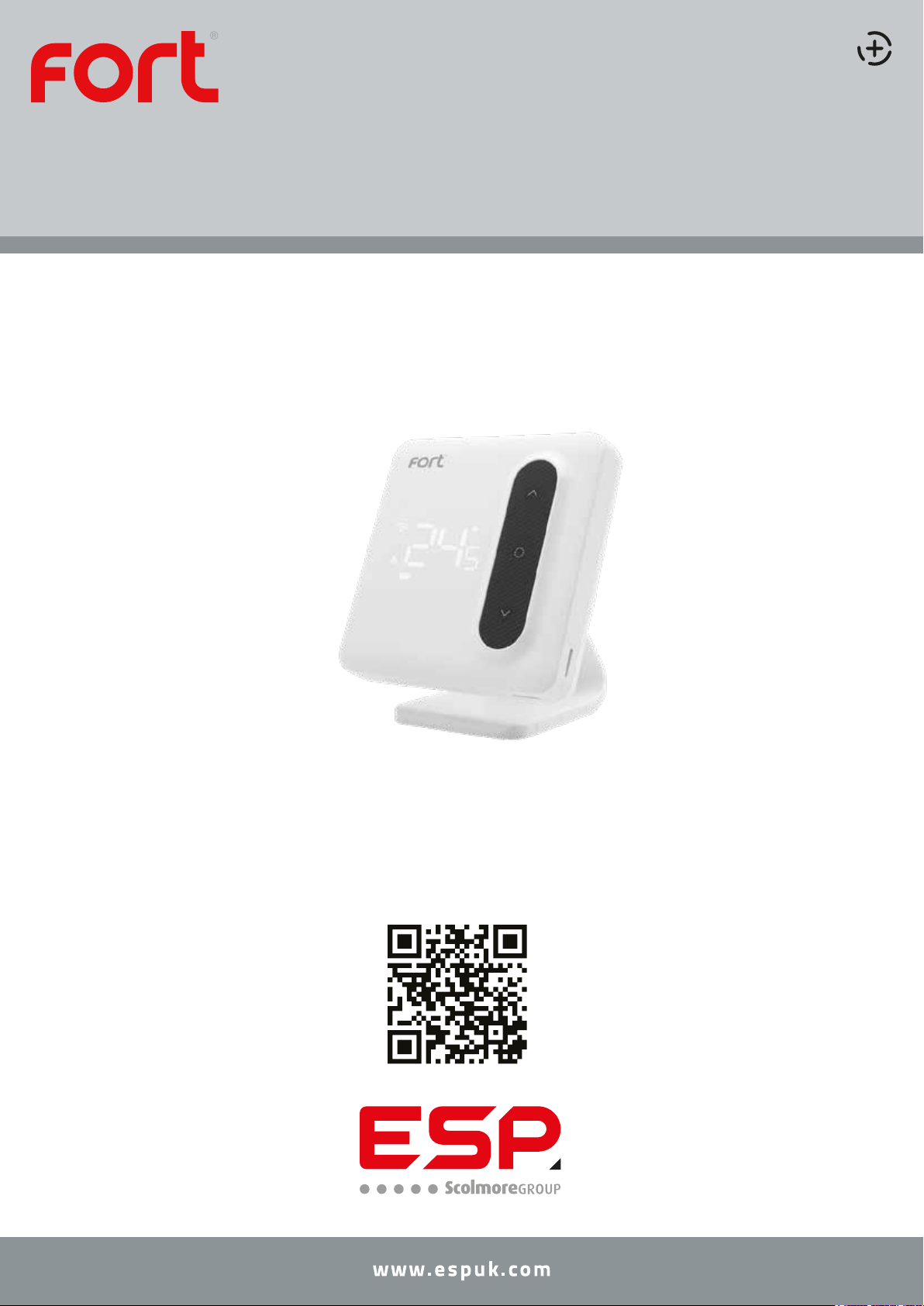
ECSPST
Full Manual
Fort Programmable Thermostat with RF and WiFi White
The latest product manuals and software is available online:
https://www.espuk.com/technical_support
REV: J22
Page 2

Contents
Features
Product Overview
Thermostat Functions
Thermostat Configuration
Thermostat Installation
Installation Plan A
Installation Plan B
Pairing the Thermostat and Receiver
Page 2
Page 3
Page 4
Page 5
Page 6
Page 7
Page 8
Page 9
Product Description
Preparation for use
Installation Instructions
How to integrate the ECSPST into Alexa
How to integrate the ECSPST into Google Home
Voice Commands
Page 10
Page 10
Page 10
Page 11
Page 12
Page 13
Page: 1
Page 3
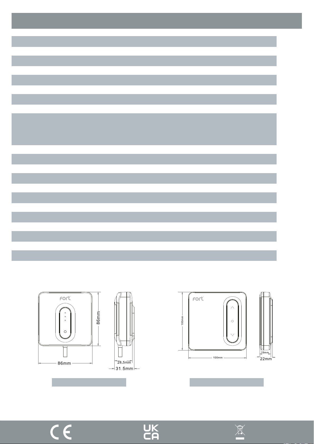
Features
• Large LED display
• Touch button
• Permanent user settings, and program settings during power loss
• One button “Holiday” mode
• Programming Periods;
• 7 Day individual, 5/2 split (Monday - Friday, Saturday & Sunday)
• 6 Separate time/temperature periods per day
• Key lock facility
• Low battery indication
• Frost protection
• Optional Intelligent function; Optimal Start
Page: 2
• Open window function
• Integrated with Clicksmart+ App
Receiver Thermostat
Page 4
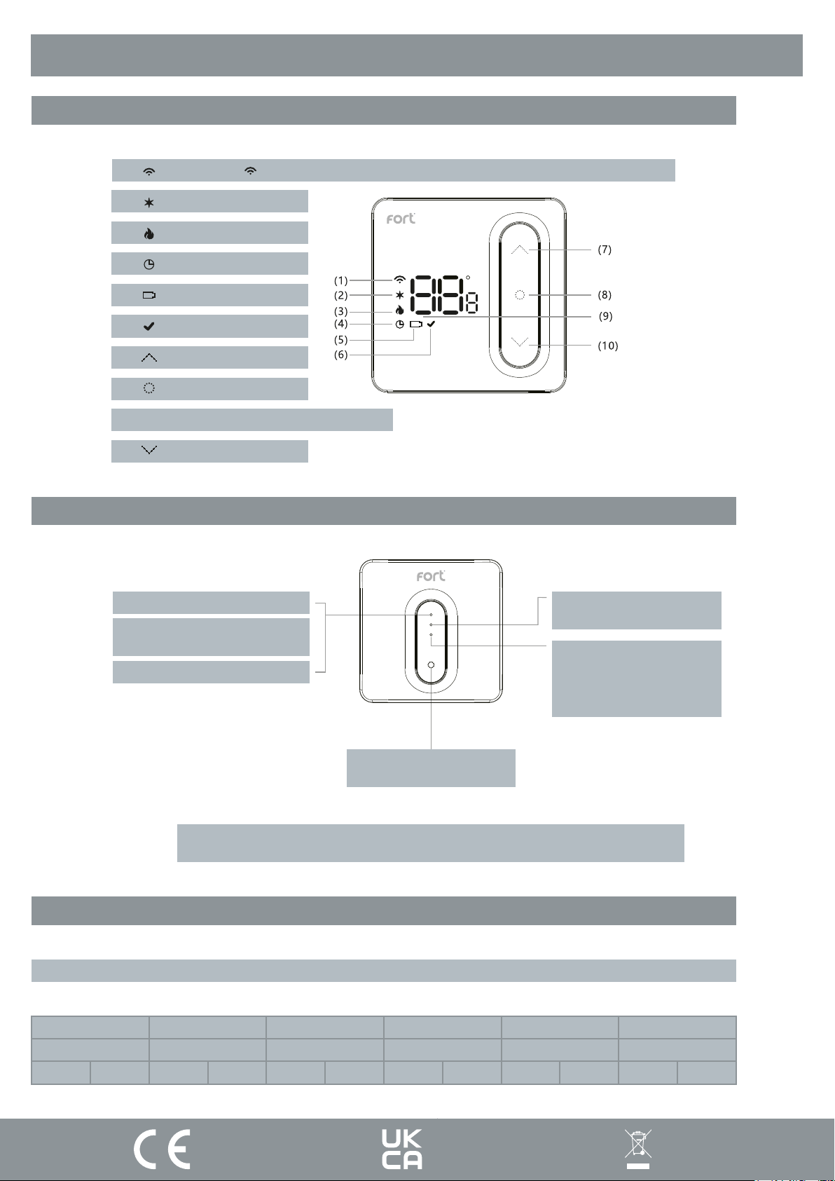
Product Overview
Thermostat
(1) Wireless icon “ ” always on when paired with the receiver, ashes when connecon is intermient
(2) Frost protecon icon
(3) Call for heat icon
(4) Programming mode icon
(5) alert
(6) Conrm icon
(7) Up
(8) ON/OFF buon
(9) Room temperature or seng temperature display
(10) Down buon
Receiver
WiFi Status Indicator
Network Pairing Mode:
The LED flashes fast or slow Green
Network Connection Successful: Blue
* To manually call for heat, press and hold the control button, until the LED turns
Default Programming Schedule
Output Indicator
Call for heat: Green
ON/OFF Indicator
Power indicator: Red
Override output status: Green
RF indicator: Yellow
Control Button
(With power indicator)
Green.
Note: The programming schedule can be configured within the ClickSmart+ app
Period 1 Period 2 Period 3 Period 4 Period 5 Period 6
Morning ON Morning OFF Afternoon ON Afternoon OFF Evening ON Evening OFF
06:00 08:00 11:00 14:00 18:00 22:0020°C 16°C 20°C 16°C 20°C 16°C
Page: 3
Page 5
Thermostat Functions
Functions
Switching between ON & Standby modes
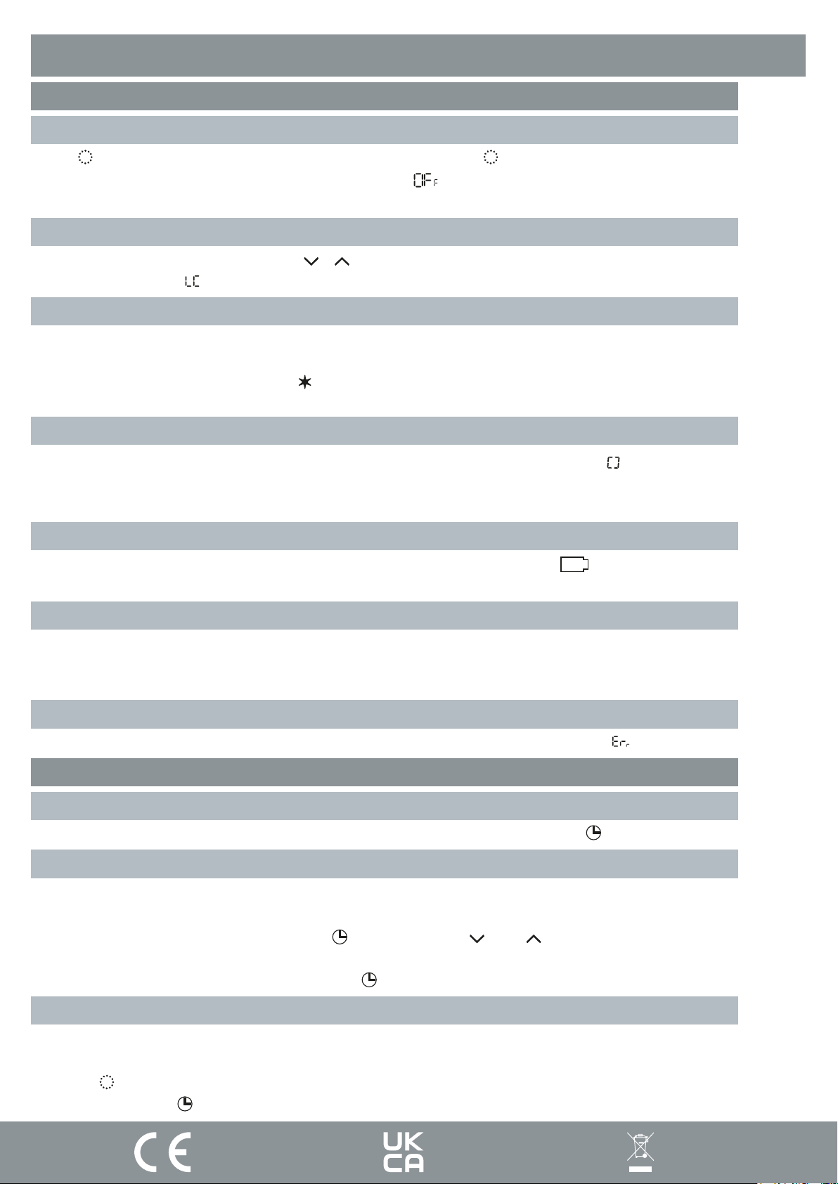
Press “ ” to turn the Thermostat into the ON mode. Press and hold “ ” again to switch the thermostat into standby
mode. When in standby mode the Thermostat will display “ ”.
Note: When in standby mode, only frost protection is active on the thermostat.
Key Lock Function
In main display interface, press and hold “ ” “ ” at the same time to lock or unlock the keys. When locked, the
thermostat will display “ ”.
Frost Protection
If the room temperature falls below 5°C, frost damage can occur. To protect your home, the Thermostat once it detects
the ambient temperature is below 5°C will send a Call for heat, until the temperature is above 8°C, and will then end
the Call for heat. This is indicated by a “ ” icon.
*This feature can be disabled in the configuration menu
Open Window/Door Detection Function
If the room temperature drops 1.5°C in 3 minutes, this function will activate and display “ ”, then turn down all heating. When the room temperature increases by 1.5°C or after 30 minutes, the thermostat will return to normal operation.
Press any button to cancel this function when it is active.
Low Power Alert
When the thermostat is critically low on power, it will alert the user by displaying “ ” to notify them to change the
batteries.
Optimal Start
If optimal start is enabled, the thermostat will start the call for heat slightly before the schedule calls for it. So that by
the scheduled start time, the ambient temperature is already at the set temperature.
*This feature can be enabled in the configuration menu
Fault
If there is damage to the internal sensor the user will be alerted by the display message “ ”.
Operating Modes
Schedule Mode
The thermostat will run according to the set schedule, the screen will display a solid “ ” icon.
Boost Mode
The boost mode, will send a call for heat until the next program in the schedule and will continue to send the call for
heat until the set temperature is achieved.
When in schedule mode (indicated by a solid “ ” icon), press the “ ” or “ ” and set the desired temperature, the
Thermostats display will flash to indicate it is activating the boost mode.
When a boost is currently active it will display the “ ” icon flashing.
Manual Mode
The “Manual” mode sets the thermostat to the desired temperature and will continue to do so until, the user ends the
Manual mode.
Pressing “ ” will toggle between Schedule mode & Manual Mode. The Thermostat will indicate it is in Manual mode
by not displaying the “ ” icon.
Page: 4
Page 6
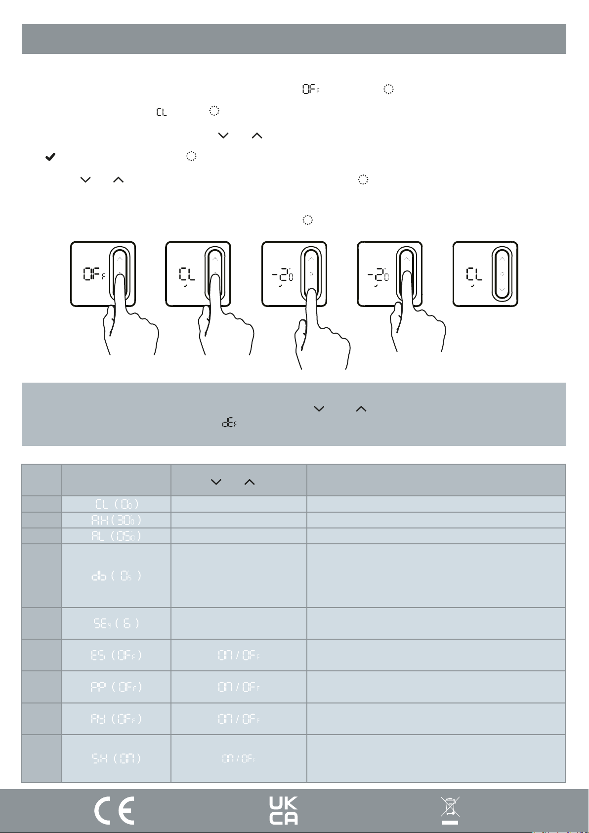
Thermostat Configuration
To configure the thermostat using its controls you will need to do the following:
(1) In standby mode indicated by the Thermostat displaying “ ”, long press “ ” to enter the configuration menu.
(2) The first item will display “ ”, press “ ” to enter the configuration for the first item.
(3) You can adjust the setting by pressing “ ” or “ ”.
(4) “ ” will flash, and then press “ ” will save current settings, and exit to the configuration menu.
(5) Use the “ ” or “ ” to select the configuration menu, and then press “ ” to enter the next configuration, and
follow the steps 3 & 4.
(6) Finally once all menus have been configured, long press “ ” to save and exit the configuration menu.
Restore factory settings:
After entering the configuration menu, press and hold both the “ ” and “ ” buttons, to restore the thermostat to
factory settings, the thermostat will display “ ” and flash 3 times.
This will remove any custom configuration setting(s) and programming setting(s)
Step
No.
1
2
3
4
5
6
Displayed
(Factory Default)
Press “ ” or “ ” to select
-4°C to +4°C
+20°C to +35°C
+5°C to +20°C
0.5°C to 3°C
4 / 6
Descriptions
Temperature calibration
Select maximum setting temperature range
Select minimum setting temperature range
Start heating conditions:
When setting temperature -Room temperature ≥ 0.5°C
(0.5~3°C option), start heating.
Room temperature ≥ Setting temperature, stop heating.
Number of programming periods per day;
2 ON & 2 OFFs / 3 ON & 3 OFFs
Intelligent function (Optimal start)
7
8
9
ON: LEDs displays on Thermostat VIA app.
OFF: LEDs don’t display on Thermostat VIA app.
Frost Protection function
Thermostat Relay Output
Thermostat LED Display option
Page: 5
Page 7
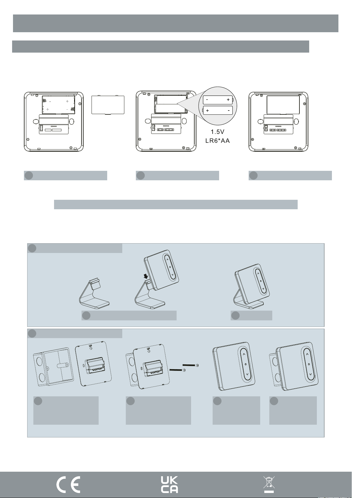
Thermostat Installation
Battery Installation
1 Take off cover 2 Install AA Batteries 3 Complete Installation
Note: Ensure the batteries are correctly installed, and the polarities are correctly aligned.
1 Desk mounted
2 Wall mounted
1 Hang Thermostat on stand 2 Complete
1
Put the back board
on the installation
box
2
Secure backplate to
installation box
using bolts
3
Secure
thermostat to
backplate
4
Complete
Page: 6
Page 8
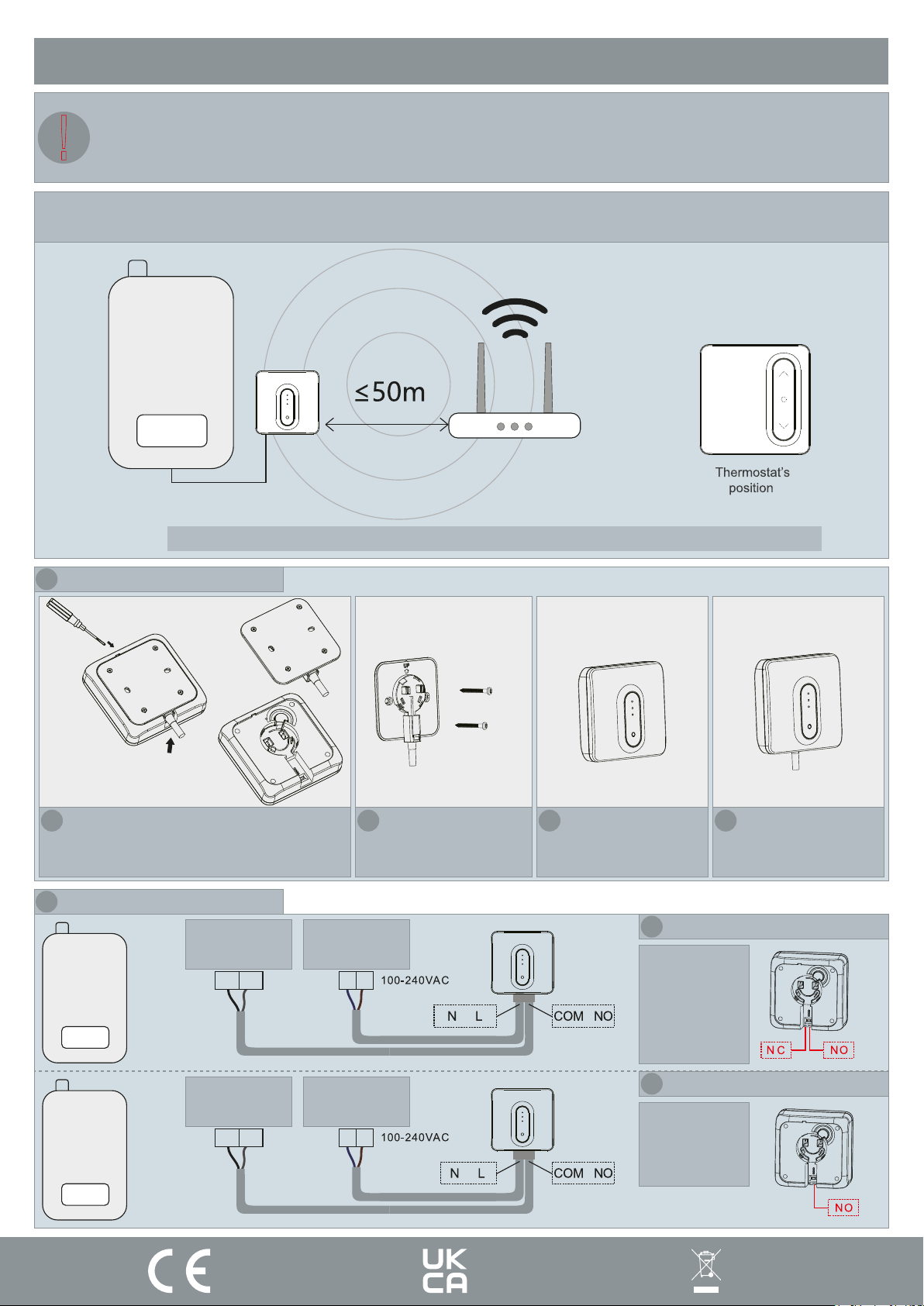
Installation Plan A
Our products are designed to comply with the recommended codes of practice and is to be installed and serviced by competent
persons in accordance with the relevant wiring regulations.
!
Warning: Before any installation or maintenance, ensure that the electrical supply is switched off at the breaker.
The receiver needs to be installed in the boilers vicinity, and within the desired wireless networks signal area.
The Thermostat can be installed anywhere within range of the receiver.
Router’s
position
Receiver’s
position
Boiler
Note: Distance between thermostat and receiver cannot be greater than 100m (open field).
1 Install receiver on the wall
1
Open backplate from the top
2 Installation Plan A Wiring
Black & Grey
Control
Cables
Boiler
2
Install the backplate
onto the wall.
Brown & Blue
Power Supply
Cables
N LTH TH
3
Clip the receiver
onto the backplate
1
Boiler type
selection;
The Thermostats
output between
N/C & N/O,
Typically N/O
4
Complete
Potential Free Relay
Boiler
Black & Grey
Control
Cables
Brown & Blue
Power Supply
Cables
N LLS LR
2
Boiler type
selection;
This boiler type
can only be N/O
230V Relay
Page: 7
Page 9
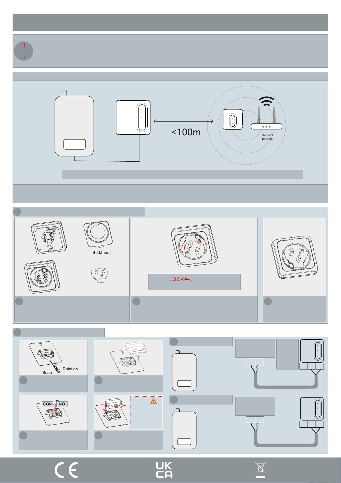
Installation Plan B
Our products are designed to comply with the recommended codes of practice and to be installed and serviced by competent
persons in accordance with the relevant wiring regulations.
!
Warning: Before any installation or maintenance, ensure that the electrical supply is switched off at the breaker.
When installing the Thermostat directly to the boiler, ensure the receiver is within the WiFi coverage area.
Thermostat’s
position
Receiver’s
position
Boiler
Note: Distance between thermostat and receiver cannot be greater than 100m (open field).
When the Thermostat is connected directly to the boiler, item 8 of the configuration should be “ON” .[Page 5].
As default it is set to OFF
1 Install receiver as gateway with plug adapter
1
Install rear bulkhead
2 Installation Plan B Wiring
Remove the buckle with a flat
1
headed screwdriver
3
Wire into connections
2
Take off safety cover
Clip
4
Reinstall safety cover
The icon “ ” aligned with the button
as shown, and then press down on the button
2
Press and rotate to clip in the adapter
Potential Free Relay
1
Boiler
Caution:
potential of 230V
on connection.
Risk of electric
shock
2
230V Relay
Boiler
4
Black & Grey
Control
Cables
TH TH
Black & Grey
Control
Cables
LS LR
Complete
If NC is
required,
terminate
into
COM & NC
N/C
N/C
COM
COM
N/O
N/O
Page: 8
Page 10
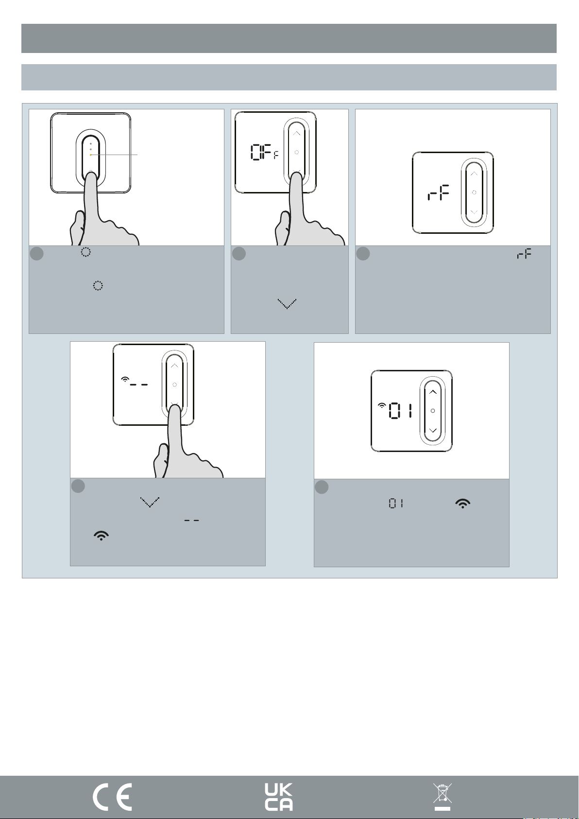
Pairing the Thermostat and Receiver
As default, the Thermostat & Receiver are pre-paired
The LED will
stay illuminated yellow
Press “ ” to turn off the receiver,
1
when in the OFF condition, press and
hold the “ ” button for at least 3
seconds, the LED will now illuminate
yellow constantly.
On the Thermostat:
4
Press the “ ” to enter pairing
mode, it will display “ ”, and the icon
“ ” will be flashing.
On the Thermostat
2
when in “Standby”
mode, press and
hold “ ” for 3s.
The Thermostat will then show “ ”.
3
If pairing is successful, the Thermostat
5
will display “ ”, and the “ ” icon
will now constantly display, and then
will automatically go back into the OFF
interface.
Page: 9
Page 11
Product Description
The WiFi Smart Thermostat (ECSPST) forms part of the ESP Fort range of smart products, and can
also be used in conjunction with Scolmores ClickSmart+ range of products.
Users are able to control the Smart Thermostat using the ClickSmart+ app, manually and using voice
controls (once correctly configured).
The ECSPST can be used to program your heating schedule, and the desired heating temperature.
Preparation for use
To use the ECSPST you will need to download the ClickSmart+ app.
Ensure that you have a mobile device running iOS 8 or higher, or Android 4.1x or higher, and a sufficient
WiFi network connection.
It is important to know your Wi-Fi network and W-Fi network’s password before pairing the Thermostat
to the ClickSmart+ app.
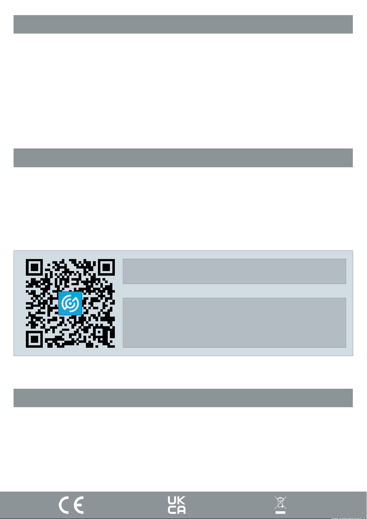
Download the ClickSmart+ App on your mobile device from the App Store or
Google Play.
You can scan the above QR code to directly download the app
Sign in or register following the instructions on the
ClickSmart+ App.
Installation Instructions
1. On the ClickSmart+ app’s home page, click on the “+” symbol in the top right of the home screen.
2. Then click on “ESP” on the left handside.
3. And finally click on “Smart WiFi Thermostat with RF”
4. The app will then display on screen instructions for pairing the ECSPST onto the Wi-Fi network.
Page: 10
Page 12
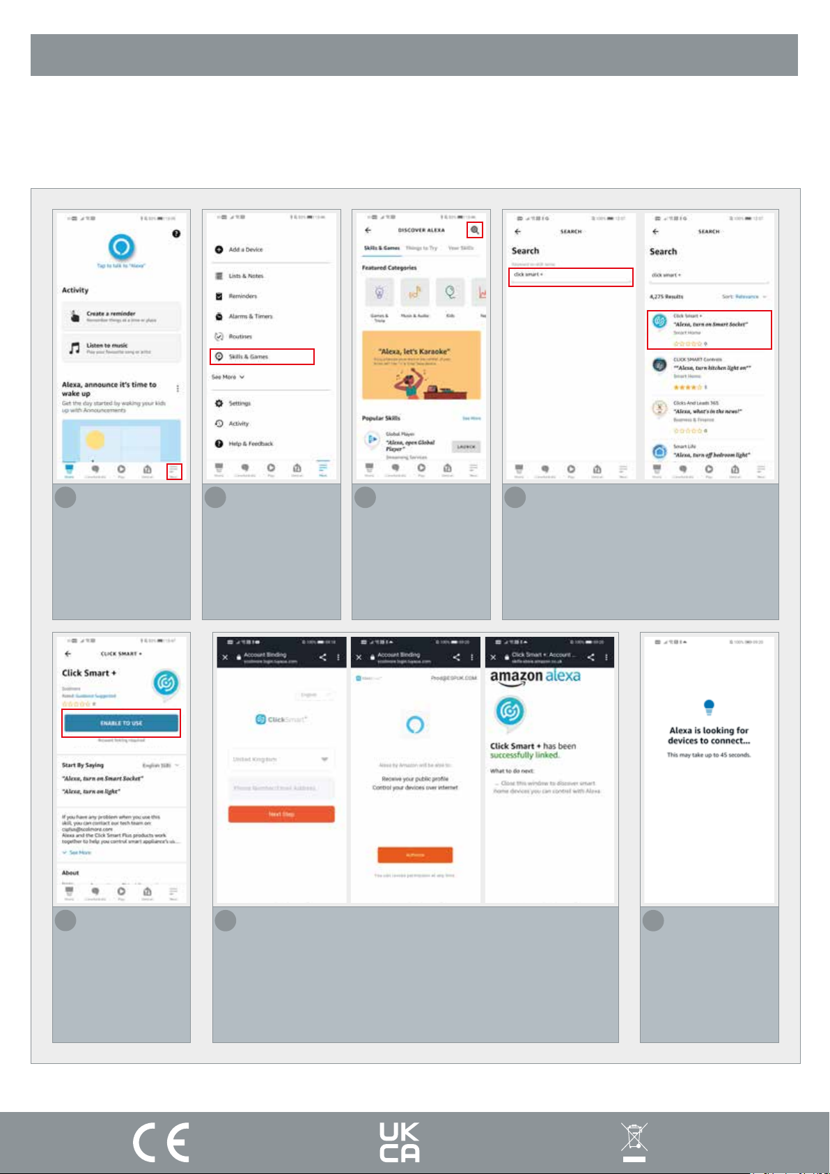
How to integrate the ECSPST into Alexa
Once the ECSPST has been configured with the ClickSmart+ App, you can then control the thermostat
using voice commands.
1
Open the Alexa
app, and press
“More” on the
bottom task bar
2
Press “Skills &
Games”
3
Press the magnifying glass
4
Search for “Click Smart +”, and click on
“Click Smart +”
5
Press “ENABLE
TO USE”
6
The Alexa app will then take you through the Account
Binding Process, you must use the ClickSmart+ Account you
used to pair your ECSPST
7
Alexa will start
searching for
Alexa Voice
compatible Click
Smart + products.
Page: 11
Page 13
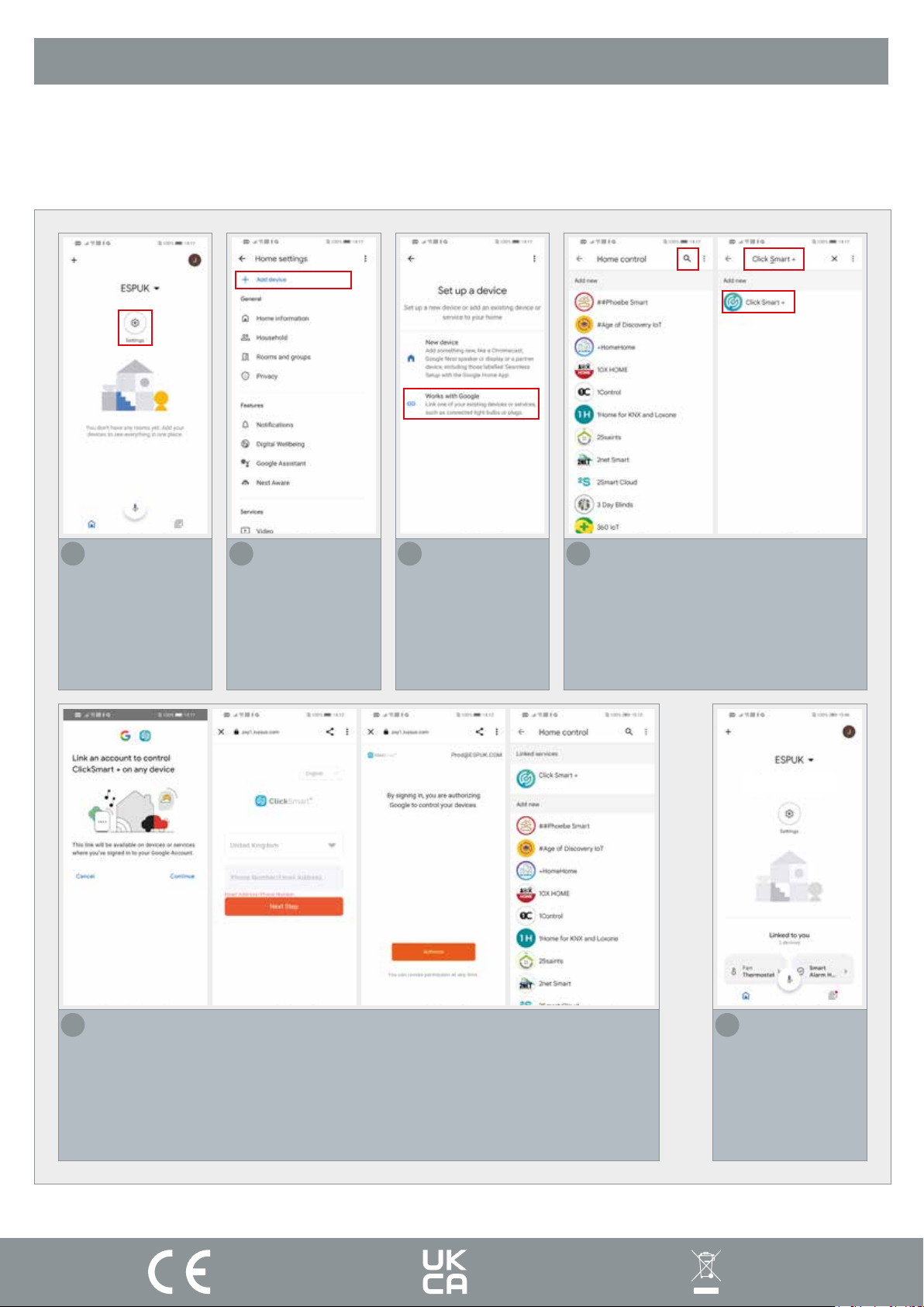
How to integrate the ECSPST into Google Home
Once the ECSPST has been configured with the ClickSmart+ App, you can then control the thermostat
using voice commands.
1
Open the Google
Home app and
press “settings”
2
Press “Add
Device”
3
Press “Works
with Google”
4
Press on the magnifying glass, then
search for “Click Smart +”, and finally
click onto “Click Smart +”
5
The Google Home app will then take you through the Account Binding Process,
you must use the ClickSmart+ Account you used to pair your ECSPST
6
Google Home will
now contain all
compatible Click
Smart + products.
Page: 12
Page 14
Voice Commands
After waking up the Alexa device or Google Home/Assistant Device, you can use the below voice commands:
Amazon Alexa
Turn On <DEVICE NAME>
Turn Off <DEVICE NAME>
What is the temperature of <DEVICE NAME>
Make it warmer in <DEVICE NAME>
Make it cooler in <DEVICE NAME>
Set <DEVICE NAME> to <NUMBER VALUE>
Google Home/Assistant
Turn On <DEVICE NAME>
Turn Off <DEVICE NAME>
Set <DEVICE NAME> to <NUMBER VALUE>
Elite Security Products UK, Unit 7 Target Park, Shawbank Road, Lakeside, Redditch, Worcestershire, B98 8YN
Tel: +44(0) 1527 51 51 50 Fax: +44(0) 1527 15 01 43 Email: [email protected]
Registered in England, Company Registration Number: 02769392, VAT Registration: GB614686525
For more product information please visit www.espuk.com
E&OE - Errors and Omissions Excepted. J22
Page: 13
 Loading...