

Page 1
APKITKPG | COLOUR VIDEO DOOR ENTRY SYSTEM
USER MANUAL
www.espuk.com
APKITKPG Manual.indd 1 26/04/2017 14:04:01
Page 2
Contents
System Components ............................................................... 3
Installation ....................................................................... 4
System Connections Example 1 ...................................................... 5
System Connections Example 2 ...................................................... 6
Lock Connections Example 1 & 2 ..................................................... 7
Door Station Programming Guide ....................................................8
User Guide ...................................................................... 10
Monitor Overview .................................................................11
Setting Monitor as Master or Slave (Default Master) ...................................12
Accessing Monitor Functions .......................................................13
Accessing Monitor Adjustments ....................................................14
Installer’s Guide ................................................................. 15
System Cabling
All system cabling (excluding mains 240vAC supply) has been tested with Cat5E UTP PVC cable.
Part Number - A8NFORCE5EUTP
Find this product online:
elandcables.com | Cables & Accessories | LAN Cable | Cat 5E UTP PVC Cable
2
APKITKPG Manual.indd 2 26/04/2017 14:04:01
Page 3
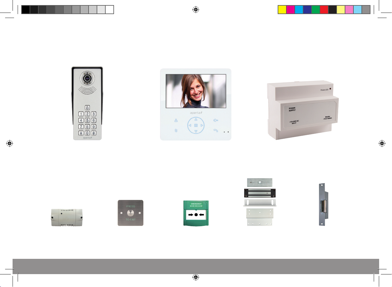
System Components
Door Station Monitor
System Power Supply
Optional Accessories
EVBPSBB
Lock Power Supply
APKITKPG Manual.indd 3 26/04/2017 14:04:03
EV-EXIT
Push To Release
EV-EBG
Emergency Release
EV-ML-250/500XT
Electro-magnetic Lock
ENTERD
Electric Lock
3
Page 4
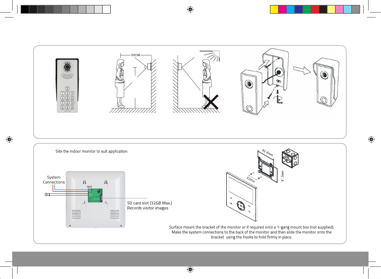
Installation
。
90
1.2 m 1.5 m~
Site the door station a
recommended 1.5 meters from
the ground, or to suit application.
Optional
door bell
connection
The camera needs to point in
the direction of where a visitor
will stand during operation.
Avoid areas of high sunlight
and noise levels.
Surface mount the sunshield of the door station and
connect the system cabling. Mount the camera to the
sunshield by fixing with the supplied hex screw.
4
APKITKPG Manual.indd 4 26/04/2017 14:04:04
Page 5
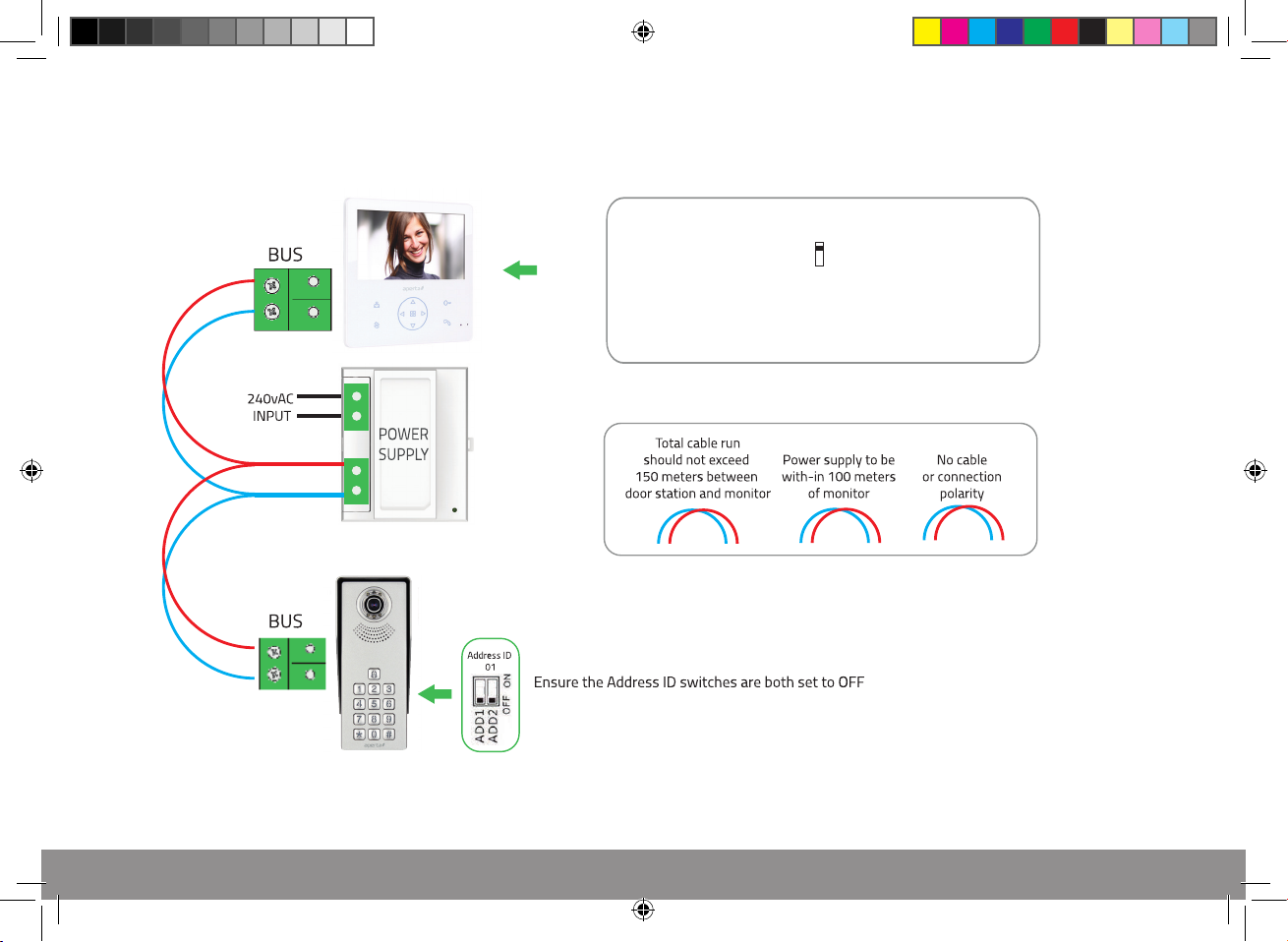
System Connections Example 1
K1
ON
1
The last monitor on the system line has
the rear ‘K1’ switched ON
APKITKPG Manual.indd 5 26/04/2017 14:04:06
5
Page 6
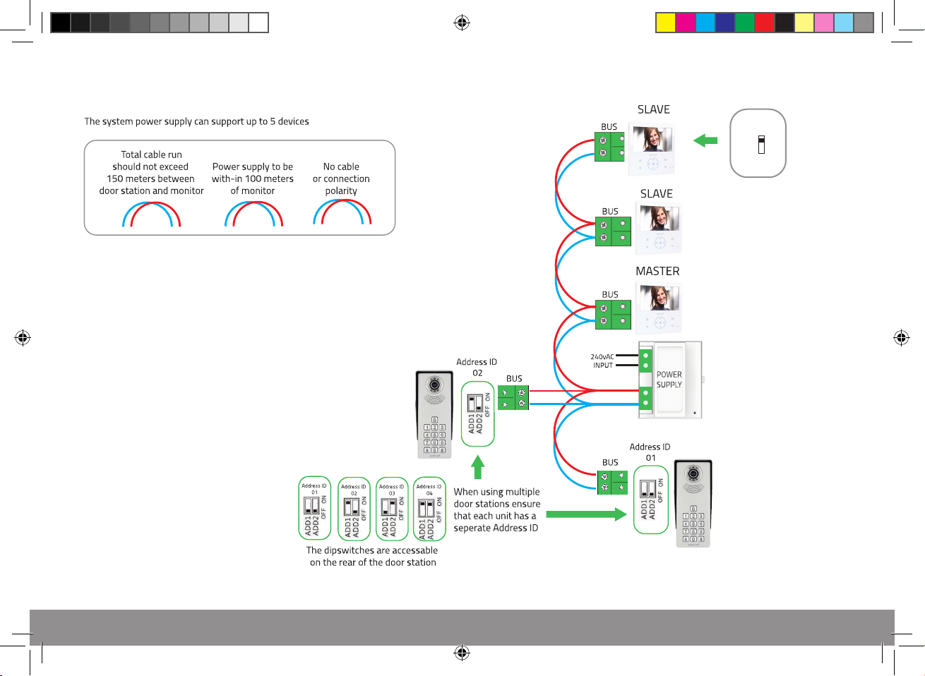
System Connections Example 2
1. The last monitor on the system line
has the rear ‘K1’ switched ON.
All other monitors ‘K1’ switch to OFF
K1
ON
1
2. Please review page XXXX to set
monitor to MASTER or SLAVE.
3. If dierent types of Monitor /handset
are being used on the same system,
please refer to the supplied instructions
to adjust Master/ Slave settings .
6
APKITKPG Manual.indd 6 26/04/2017 14:04:07
12 to set
Page 7
N/A
N/A
N/A
N/A
N/A
N/A
N/A
APKITKPG Manual.indd 7 26/04/2017 14:04:07
7
Page 8
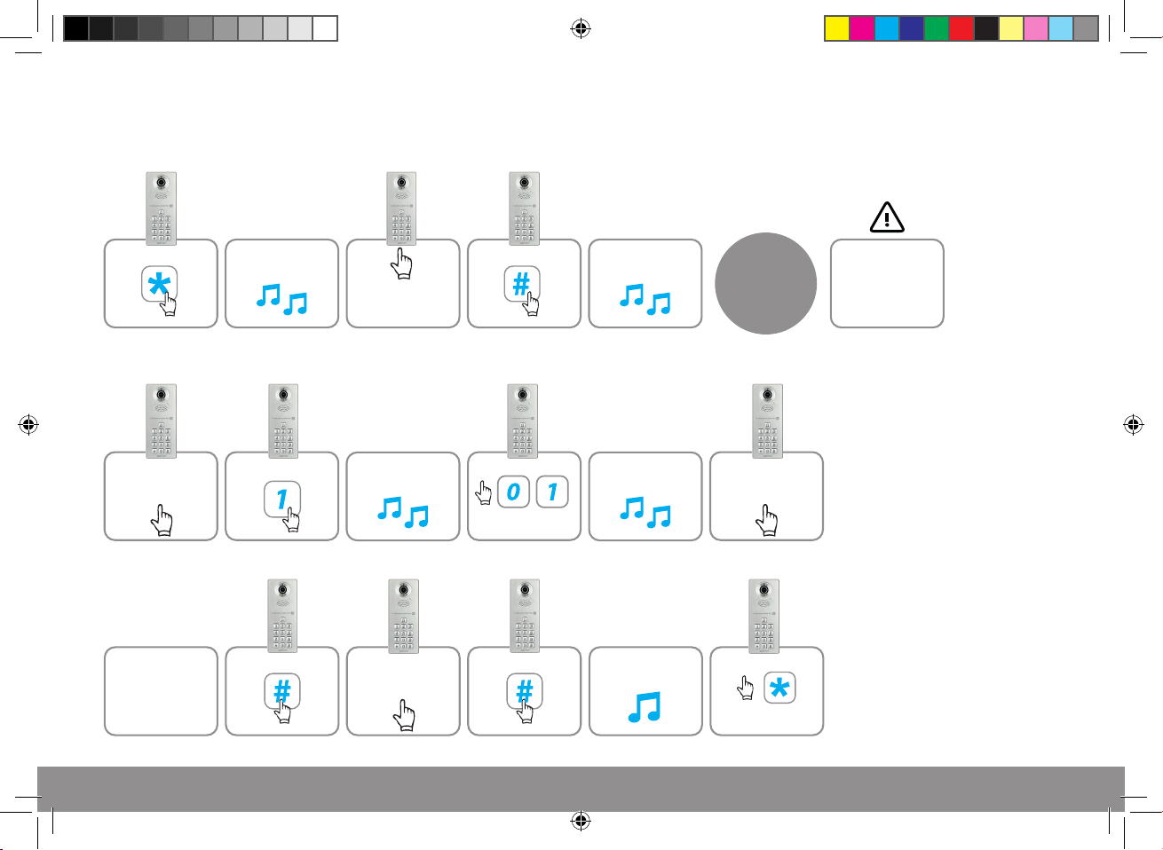
Door Station Programming Guide
Entering Administration Mode
Press
Setting a lock release code
Enter
Administration
Mode
>
Continue
2 tones
will sound
Press
Press
Input administrator
code
(Default: 123456)
2 tones
will sound
Re-enter 4 digit
code required for
door release
Press
Press
For code
location number
Press
2 tones
will sound
2 tones
will sound
A long tone
will sound
Administration
Mode has been
entered
Enter 4 digit code
required for
door release
Press
to exit and
complete setup
The Administrator
code will not
release the door.
A lock release code
is required to be
programmed
8
APKITKPG Manual.indd 8 26/04/2017 14:04:08
Page 9
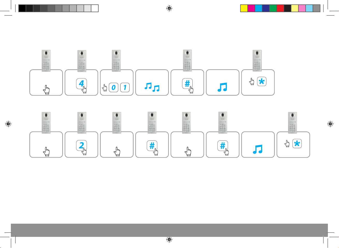
Deleting a lock release code
Enter
Administration
Mode
Press
Changing the Administrator code
Enter code
Location Number
2 tones
will sound
Press
A long tone
will sound
Press
to exit and
complete setup
Enter
Administration
Mode
APKITKPG Manual.indd 9 26/04/2017 14:04:08
Press
Enter new 6 digit
Administration
Code
Press Press
Re-enter new
6 digit
Administration Code
A long tone
will sound
Press
to exit and
complete setup
9
Page 10
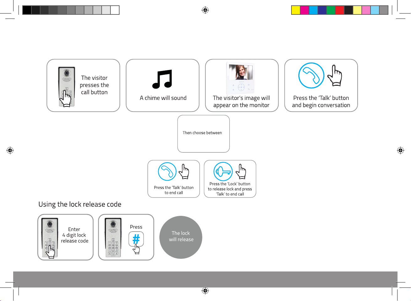
User Guide
A B C D
1 2
10
APKITKPG Manual.indd 10 26/04/2017 14:04:09
Page 11
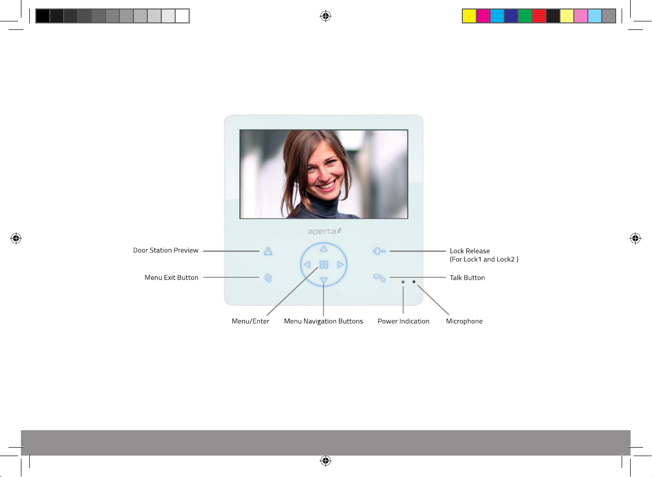
Monitor Overview
The following monitor instructions are designed to be a quick start guide alongside the informative general user
interface (GUI) . The instructions are not exhaustive and are designed to lead the user quickly to the most often
required aspects of the unit.
APKITKPG Manual.indd 11 26/04/2017 14:04:09
11
Page 12
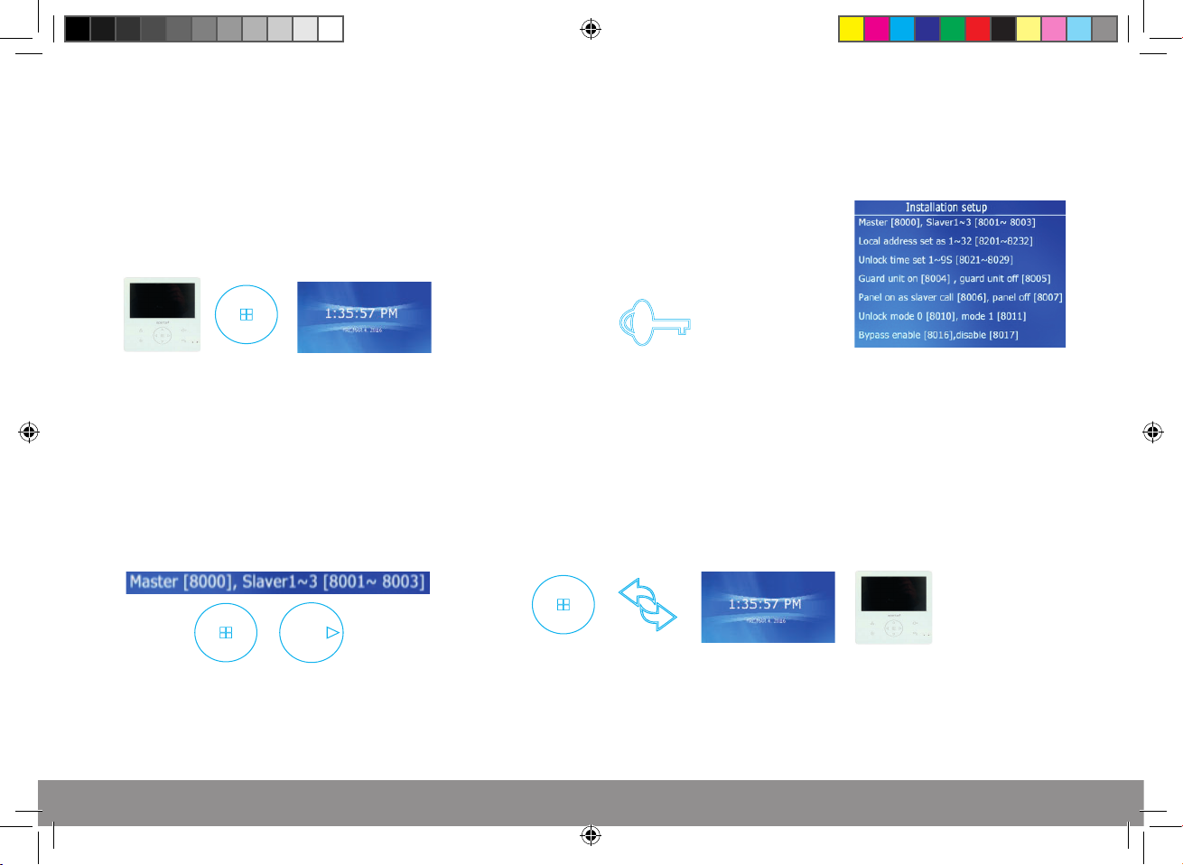
Setting Monitor as Master or Slave (Default Master)
1. In standby mode press
the menu button and the time screen
will display.
3. Press the menu button and use
the right arrow to toggle between
Master and Slave position.
2. Press and hold the Key
for 5 seconds and the Installation setup
screen will display.
4. Press the menu button to save setting, and press
the exit symbol twice. After 10 seconds the monitor returns
back to standby.
12
APKITKPG Manual.indd 12 26/04/2017 14:04:09
Page 13
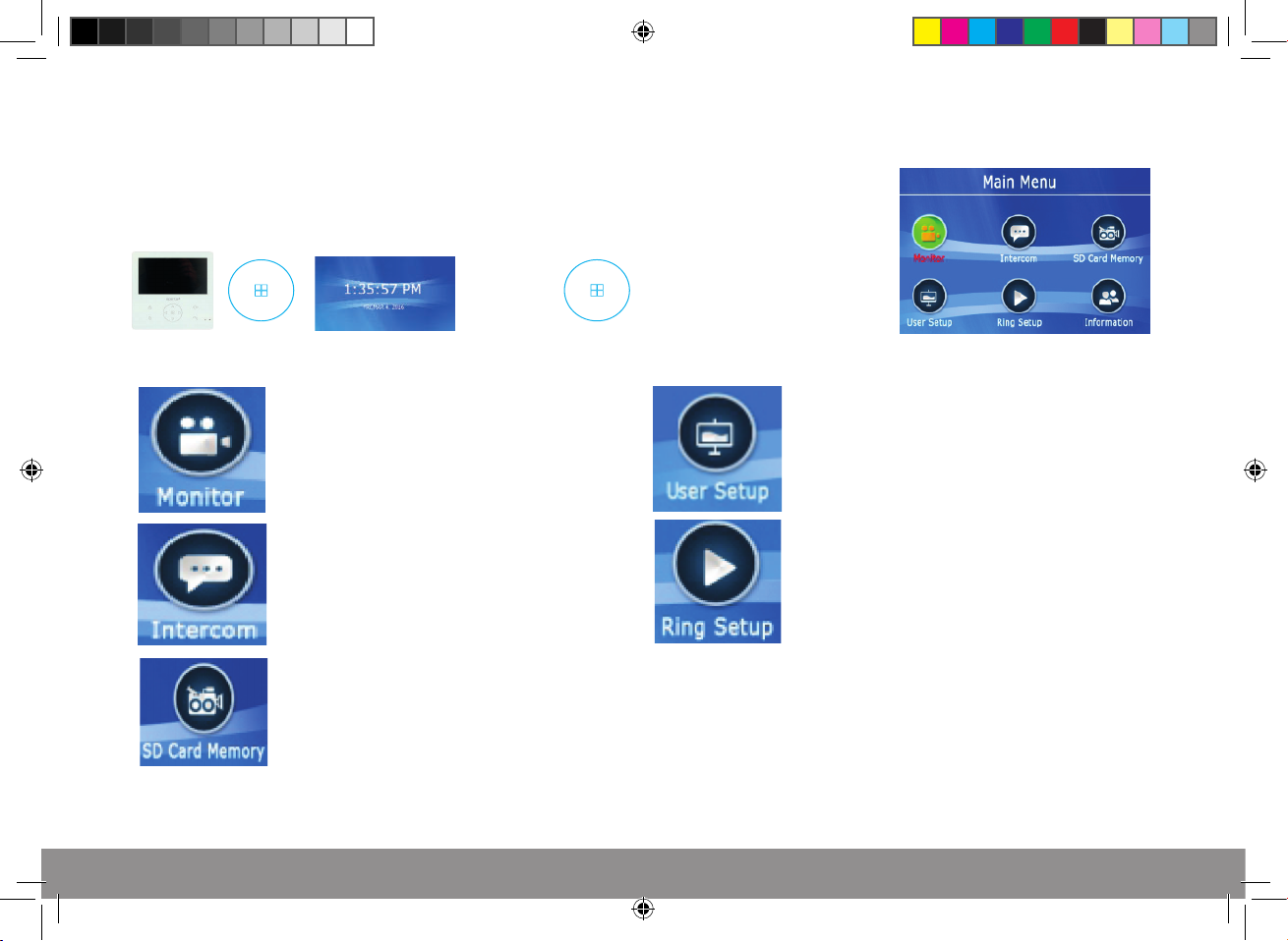
Accessing Monitor Functions
1. In standby mode press
the menu button and the time screen
will display.
PREVIEW option for all
system door stations.
INTERNAL CALL options
RECORDING & VIEWING
options can be found in the
‘SD Card Memory’ menu
2. Press the menu button whilst on the
time screen and the main menu
screen will display.
DATE and TIME settings can be found
in the ‘User Setup’ option. Also includes ‘ring
mode’ for selective ringing times.
RING TONE
Options for incoming, internal and optional
door bell tone selections.
APKITKPG Manual.indd 13 26/04/2017 14:04:09
13
Page 14
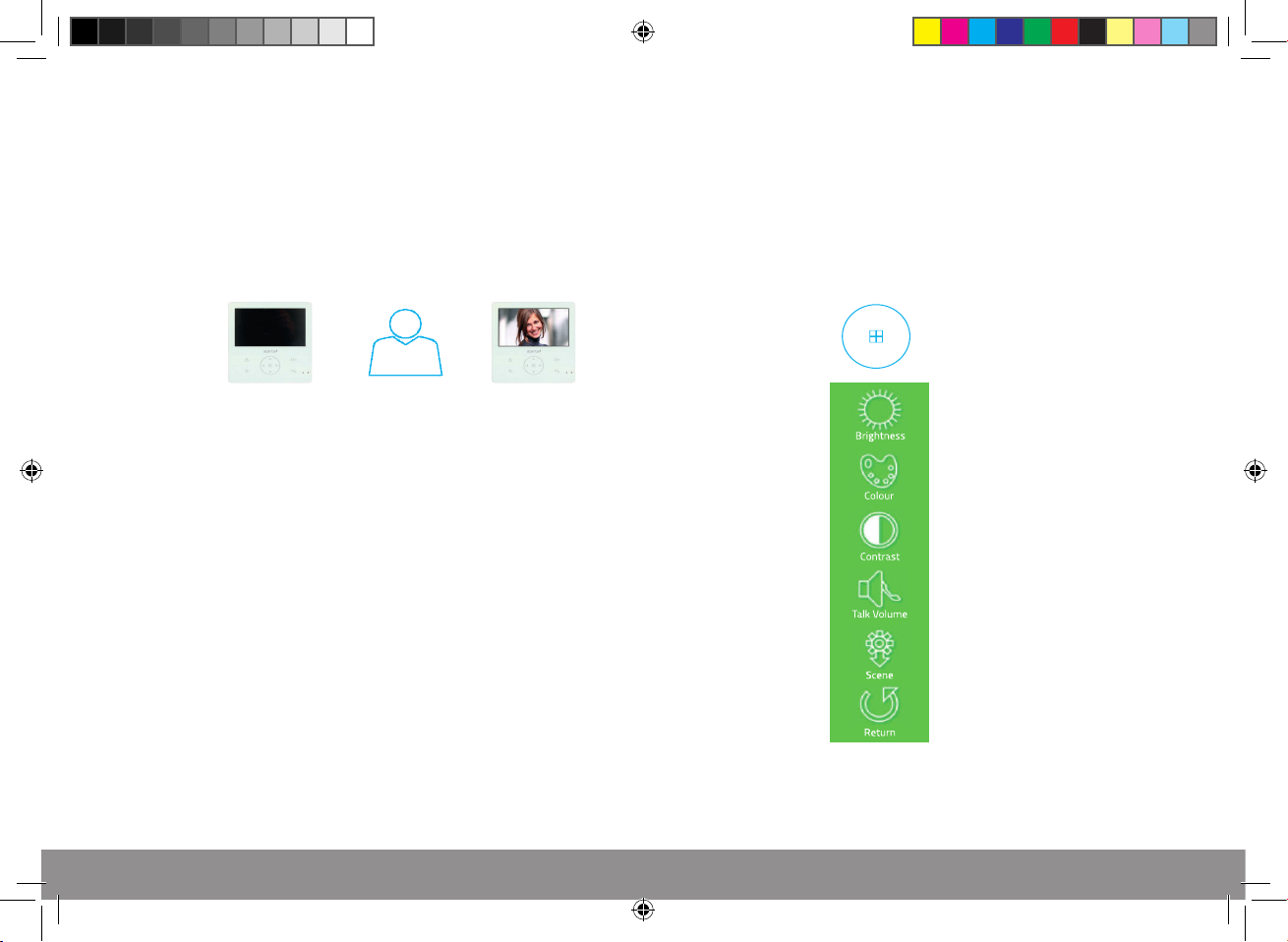
Accessing Monitor Adjustments
1. In standby mode press
the preview button and the door station’s
image will display.
2. During the preview press the menu button
the adjustment controls will appear.
14
APKITKPG Manual.indd 14 26/04/2017 14:04:09
Page 15
Installer’s Guide
Master / Slave Setting
In the event of no video
or audio signals coming
from the monitor, or if the
call button or audio cannot
be activated on the door
station, check the following;
In the event of a lock
release issue,
check the following;
When using multiple monitors on 1 system;
Only the 1 handset set as the MASTER will display an image when the door station is activated.
All other monitors will ring, and will display the image once the ‘Talk’ button is pressed.
A That the system is powered sufficiently.
B Each monitor needs to be set to a MASTER or SLAVE position
C All system cabling is secured and properly connected.
D All system cabling is clear of breaks or short circuits.
E Bench test the system if the issue cannot be found.
A The user instructions and operation of the monitor has been understood.
B That the lock is powered sufficiently.
C All system cabling is secured and properly connected.
D All system cabling is clear of breaks or short circuits.
E On the rear of the door station, ensure the lock output is switching when activated by the monitor.
APKITKPG Manual.indd 15 26/04/2017 14:04:09
15
Page 16
Elite Security Products
Unit 7, Target Park, Shawbank Rd
Lakeside, Redditch B98 8YN
Telephone: 01527 51 51 50
Fax: 01527 51 51 43
email: [email protected]
E&OE - Errors and omissions excepted. D17
www.espuk.com
APKITKPG Manual.indd 16 26/04/2017 14:04:09
 Loading...