

Page 1
YardMaster
Outdoor Movie Manual Projector Screen
Yard Master Manual
user guide before utilizing the screen. Correct usage and maintenance will ensure a long product
The Yard Master Manual is a non
that brings media room quality to your outdoor spaces. Its sleek aluminum casing beautifully
accessorizes your backyard, patio, pool deck or anywhere a gathering for evening movie time is
Outdoor Projection Screen Disclaimer
r leave your projection screen out and exposed to direct sunlight.
prolonged exposure to the sun’s ultraviolet radiation degrades the chemical bonds causing the
material to eventually decompose.
grade reflective qualities. Eventually nature will completely destroy even synthetic materials. For
this reason, the Yard Master Manual has a retractable design that allows the material to be drawn
ing to be shielded from solar radiation.
Dust, dirt and scratches on the projection surface will affect the picture quality, please take note
of the points below to prevent that from occurring:
1. Do not touch the projection surface with your hands
2. Do not write or draw on the projection surface
3. Do not use fingers or sharp objects to point on the projection surface; this will damage
damp cloth to clean t
5. Use clean water when dampening the cleaning cloth and do not rub against the material
To avoid damage and injury, the screen should only be operated by adults.
series
projection screen! Please read through this
electric outdoor projector screen for wall and patio i
Regardless of screen brand,
he material to lose its theater
he projection surface; do not use chemical cleaning
Thank you for choosing the
life
Product Description:
appropriate.
Neve
Manual
User’s Guide
-
nstallations
up into its protective cas
Care & Use Instructions
◆
the screen material.
4. Use a softagents or alcohol.
to clean it.
◆
Photo degradation first causes t
-
Rev041916
www.elitescreens.com
1
Page 2
Please consult a professional installer, Elite Screens is not liable for faulty installations.
Mark the location of where the screen is to be installed, drill your holes and insert the
Mounting Brackets (
Anchor
Mounting Brackets (
securing the back of the case to Fix Plate 2. Make sure the case slots are securely attached to the
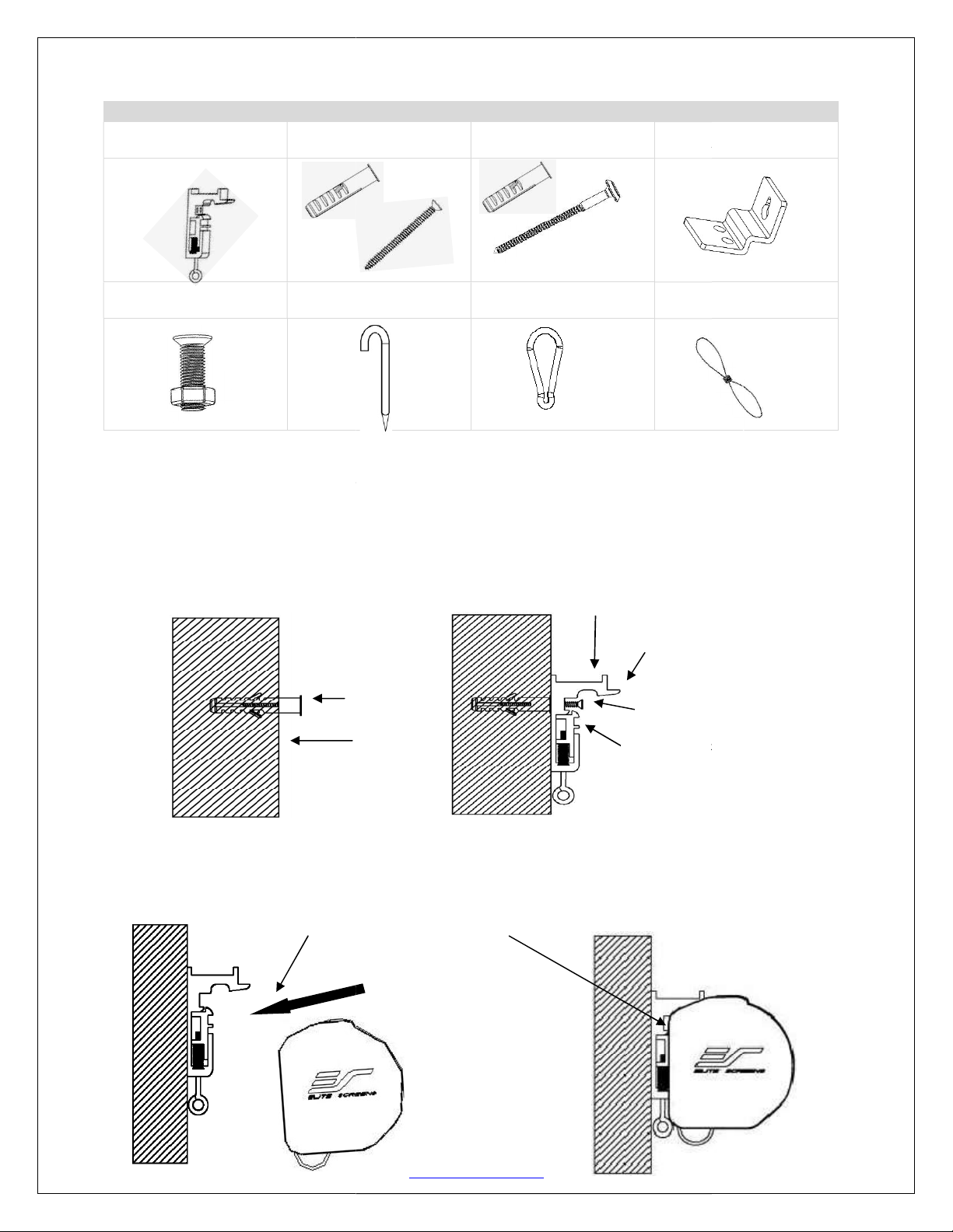
ardware Parts List for Yard Master Manual Series
B. M10 Anchor and
M4x50 Screw
Curved
M4x50 Screws (
by inserting the top of the case to Fix Plate 1 and
D. Suspended Ceiling
Bracket Connector
H. Elastic String
Mount
ing bracket
M4x50 Screw
Mounting Bracket
A. Mounting Bracket
x2pcs
H
x4pcs
C. M10 Anchor and
M5x50 Screw x1pc
x2pcs
E. M5x15 Screw& Bolt
x4pcs
F.
Installation Instructions
Flush Mount to the Wall
1.
M10Anchors (B).
2. Install the
Nail x2pcs
G. Hook x2pcs
A) to the wall and secure with the
Mounting Bracket
x2pcs
B).
3. Attach the screen to the
mounting brackets.
Mounting Bracket
Fix Plate 1
Wall
A)
Mounting Bracket
Fix Plate 2
Fix Plate 1
Fix Plate 2
Rev041916
www.elitescreens.com
2
Page 3

Mounting Bracket Case Slot 1
Case Slot 2 Screen Case
Flush Mount to the Ceiling
1. Mark the location of where the screen is to be installed, drill your holes and insert the
M10Anchors (B).
2. Install the Mounting Brackets (A) to the ceiling and secure with the M4x50 Screws (B).
Ceiling M10 Anchor
Mounting Bracket Fix Plate 1
Mounting Bracket
M4x50 Screw
Mounting BracketFix Plate 2
3. Attach the screen to the Mounting Bracket (A) by inserting the top of the case to FixPlate 1 and
securing the back of the case to Fix Plate 2. Make sure the case slots are securely attached to the
Mounting Bracket (A).
Fix Plate 2
Fix Plate1
Rev041916
www.elitescreens.com
3
Page 4

Suspended Ceiling using Chains (additional hardware required)
You can also hang the screen on a ceiling by using chains
Suspended Ceiling Bracket Connector (
M5x15 Screws & Bolts (
Insert chains (not included) through the loop holes of the
from the Mounting Brackets
Pull down on the Mounting
wall/ceiling followed by the top of the case.
Mounting Bracket (
Suspended Ceiling Bracket
Bracket Release Tab and remove the bottom case away from the
1.
2. Connect the
secure with the
E).
(not included).
D) to the
A) and
M5x15 Bolt
(E)
Mounting Bracket
(A)
3.
Connector(D).
Suspended Ceiling Bracket Connector
Loop Holes
(D)
Screen removal
1.
(D)
Suspended Ceiling Bracket Connector
M5 M5x15 Screw (E)
Release Tab
Pull bottom of case first away from wall/ceiling
Rev041916
www.elitescreens.com
4
Page 5

Screen Operation
1. Pull the screen down from the lanyard or from the handle
only in a 90-degree angle. The screen is designed to stop at any
location. To achieve this, make sure to pull straight down and
allowing the screen to come up to lock into place. Do not
attempt to pull the screen down by the surface or touch the
screen, as it will damage the screen and void the warranty.
2. To retract the screen, simply pull the screen down more than
2 inches and retract the screen back releasing it up gently. The
screen is equipped with a SLOW RETRACT MECHANISM
which allows the screen to slowly retract without the need to
hold on to the handle or lanyard. Simply release the handle and
the screen will retract by itself into the housing.
Attention: If the screen does not unlock, carefullypull the screen straight down with a little force.
Always pull the screen down at a 90-degree angle.
Securing the weight bar location
1. Pull the screen down until you have reached the
desired location.
2. Mark the drill-hole area of where the screw is to be
installed, then retract the screen.
3. Drill the hole and insert an M10Anchor (C), secure it
with anM5x50 Screw (C). Allow a 1-inch gap between
the wall and screw head to allow room for
the weight bar and pull handle to release freely.
4. Pull the screen down and secure it to the screw location.
Make any adjustments if there are any
deviations.
Note: Remove the screw when not in use
any longer to avoid an accident.
Minimum 1-inch clearance required
Rev041916
www.elitescreens.com
5
Page 6

Iron Ring
Hook
Elastic
String
Curved
Nail Ground
How to ground the screen
1. Attach the Hook (G) into the Iron Ring, and join the Hook (G) and Curved Nail (F) using the
Elastic String (H)
2. Drive the Curved Nail (F) into the ground and stretch the Elastic String (H) in the direction
of the Curved Nail (F) to secure screen to the ground and supply adequate tension to the
screen.
For more information, technical support or your local EliteScreens
www.elitescreens.com
Rev041916
contact, please visit
www.elitescreens.com
6
 Loading...