

Page 1
W
hit
e
Boa
rd
Scre
e
n™
Serie
s
Dry-Erase Ambient Light Rejecting Projection Screen
User’s Guide
Thank you for choosing the WhiteBoardScreen™ Series dry-erase whiteboard projection screen! Please
read through this user guide before utilizing the screen. Correct usage and maintenance will ensure a
long product life.
Precautiona ry Notes:
Before using the dry-erase function of your whiteboard screen, please make note of the following
instructions to properly maintain and clean your dry-erase surface projection screen. (These Whiteboard
cleaning tips are just as relevant with any dry-erase writing surface as they are with our WhiteboardProjection Screens.)
1.Only use a high density foam eraser when removing dry-erase markings from the Whiteboard screen.
2. Do not use abrasive erasers as these may scratch the surface of the screen.
3. Never spray the whiteboard cleaner solution onto the surface while marker writing is present and then
attempt to use a high density foam eraser to remove. This will only smear the dry-erase marker ink
making the surface more difficult to clean and will likely ruin the foam eraser.
4. If there are any dry-erase markings left behind even after attempting to remove them using our high
density erasers, spray our whiteboard cleaning solution directly onto the screen surface and use only a
soft microfiber cloth to wipe-down and clean the area.
For a video demonstration, please visit: http://www.elitescreens.com/whiteboardscreen-cleaning
If replacement cleaning accessories are needed, please visit the Whiteboard cleaning accessories section
of our website at
http://www.elitescreens.com/clean-whiteboard
Rev. 04 /25/17 DR elitescreens.com
Page 2
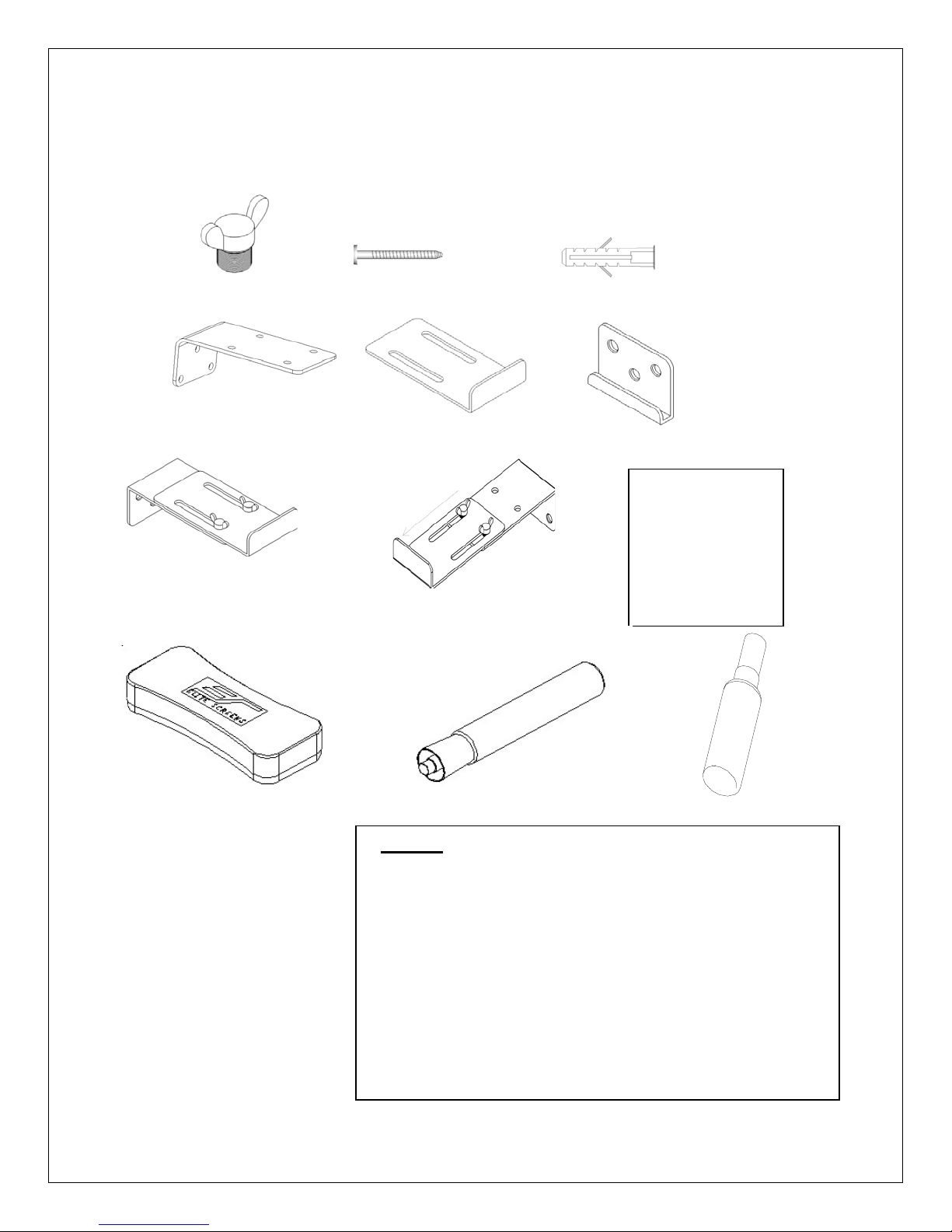
Hardware and Parts List
Please make sure all parts listed are included before proceeding with installation.
a b c
h
G and H are
Actual individual
parts included but
configurations only by
combining parts (d)
and (e) with the
butterfly screw.
not
d e f
g
I j k
Note: The
Series
the WhiteBoardScreen™.
Rev. 04 /25/17 DR 1 elitescreens.com
WhiteBoardScreen™
eraser should only be used for
Parts List
a. Qty 4–Butterfly screw
b. Qty 12–Wall screw
c. Qty 12–Hollow wall (or drywall) anchor
d. Qty 2–Top hanging wall brackets (to the wall)
e. Qty 2–Top hanging whiteboard brackets (to the whiteboard)
f. Qty 2–Bottom hanging bracket
g. For whiteboard diagonal size 60 (4:3) inches
h. For whiteboard diagonal 80(4:3), 96 (16:9) inches.
i. Qty 2–whiteboard eraser
j. Qty 2–Dry‐erase pens
k. Qty 1–WhiteBoardScreen™ cleaner
Page 3

X2
Installation
1. Mark the location the WhiteBoardScreen™ will be installed and drill your holes for all Top Hanging Wall
Brackets (fig.1) and Bottom Frame Hanging Brackets (fig.2).
2. Attach the Top Hanging WhiteBoardScreen™ Brackets (fig.3) to the Top Hanging Wall Brackets (fig.1) with the
Butterfly Screws according to the size of the WhiteBoardScreen™ as specified in fig.4 and 5
3. Next, affix the Top Hanging Wall Brackets (fig.1) and the Bottom Frame Hanging Brackets (fig.2) to the drilled
locations and install the
4. Lastly, hang the WhiteBoardScreen™ on the brackets (fig.7).
wall screws (fig.6).
below.
Fig.1 Fig.2 Fig.3
Fig.4 Fig.5
Note:
Fig.4
Bracket
Fig.5 Recommended Bracket configuration for whiteboard 80 inch (4:3) and 96 inch (16:9)
configuration for whiteboard 60 inch diagonal (4:3) screens
Cx 12
D
2
BX1
Rev. 04 /25/17 DR 2 elitescreens.com
Fig.
6
AX4
Fig.7
Page 4

Desktop Projector Mode
Rev. 04/25/17 DR 3 elitescreens.com
Overhead Projector Mode
Page 5

Notice to Installer:
Please use the following installation instructions to obtain superior optical performance from the
StarBright 4 Angular Reflective ALR (Ambient Light Rejecting) Screen.
Make sure to follow these instructions in order for the StarBright 4 to perform correctly.
•Angular‐Reflective material is not compatible with ultra/short‐throw projectors
•Minimum lens throw ratio 1.5x image width
•Ambient light must not come from the same direction as the projector
Since angular-reflective means that the projected image will reflect at the mirror-opposite angle, it is
important to position the projector so that the viewer will get the best possible image.
Step 1: Establish the general “eye level” of the viewers
Step 2: Set the appropriate projection level
Step 3: Adjust the screen height level and projection angle
Input Angle (A) = Output Angle (B) aligns with the viewer’s angle
Rev. 04/25/17 DR 4 elitescreens.com
Page 6

Recommended Installation Locations for desktop and overhead projector installations
The StarBright4 material used in this WhiteBoardScreen™ has a special high gain that is
angular reflective. In order to take full advantage of this special material, it is important
that the WhiteBoardScreen™ is installed properly so that the projected image is viewed
within the recommended viewing angle.
It is normal for some viewing areas to be less bright than the center due to the nature
of the screen material. It is not a defect and minor “hot spotting” will occur as a result.
The below charts will assist in determining several factors to consider to help you with your
installation. Please note that these are only recommendations.
Desktop
projector
installation
Model
Number
WB60V
WB60V
Overall
Width
1190.0 930.0 1000‐1200 1950‐2950
Overall
(W)
Height
(H)
46.9 36.6 39.4‐47.2 76.8‐116.1
Installation
Height (A)
Suggested
Projection
Distance (B)
Sitting
View
Distance
(C1)
160
6.3
Standing
View
Distance
(C2)
Unit: mm
114
Unit: Inches
4.5
Suggested
Projection
Height
(D)
800‐1000 1200 1200 1700
31.5‐39.4 47.2 47.2 66.9
Viewer
Distance
(E)
Sitting
View
Height
(F1)
Standing
Sitting
Standing
View
Height
(F2)
View
View
Sitting
View
Angle
(01)
Standing
View
Angle
(02)
9°
9°
6°
6°
Rev. 04/25/17 DR 5 elitescreens.com
Page 7

S
A
Unit: mm
WB80V
Unit: inches
WB80V
Model
Number
Overall
Width
1630.0 1230.0 1000‐1200 2750‐3750
64.2 48.4 39.4‐47.2 108.3‐147.6
(W)
Overall
Height
(H)
Installation
Height (A)
Suggested
Projection
Distance (B)
Sitting
View
Distance
(C1)
228
9.0
tanding
View
Distance
(C2)
145 800‐1000 1200 1200 1700
Suggested
Projection
Height
(D)
5.7
31.5‐39.4 47.2 47.2 66.9
Viewer
Distance
(E)
Sitting
View
Height
(F1)
Standing
View
Height
(F2)
Sitting
View
ngle (01)
10°
10°
Standing
View
Angle (02)
6°
6°
Standing
Sitting
Desktop Installation explanation:
A= Installation Height (Floor to bracket drilling hole)
B= Suggested Projection Distance (Projector to screen)
C1= Sit View Distance (The brightest view when people are sitting down in relation to the angle setting in
F1) C2= Stand View Distance (The brightest view when people are standing in relation to the angle
setting in F2)
View
View
****User selectable average recommendations****
D= Suggested Projection Height (Floor to project center)
E= Viewer Distance (User to
projector) F1= Sit View Height
F2= Stand View Height
****The basis of height is from an average height****
θ1= Sit View Angle (Screen slope angle between screen and wall to achieve brightest view)
θ2= Stand View Angle (Screen slope angle between screen and wall to achieve brightest view)
(*****Relation between C1, F1 and θ1; Relation between C2, F2 and θ2*****)
W= Overall Width
H= Overall Height
Rev. 04/25/17 DR 6 elitescreens.com
Page 8

Overhead Projector installation
Models
WB60V
WB60V
Overall
Width
(W)
1190.0 930.0
Overall
Height
(H)
46.9 36.6
Installation
Height (A)
2340
92.1
Suggested Projection
Distance (B)
1950‐2950 2500
76.8‐116.1 98.4
Unit: inches
Ceiling Height
Unit: mm
(C)
Suggested Offset
(D)
130
1200 1200 1700
5.1
47.2 47.2 66.9
Standing
Viewer
Distance (E)
Sitting
View
View
Sitting View
Height (F1)
Rev. 04/25/17 DR 8 elitescreens.com
Standing View
Height (F2)
Page 9

Sitting View
Standing View
Models
WB80V
WB80V
Overall
Width (W)
1630.0 1230.0 2340 2750‐3750 2500
64.2 48.4
Overall
Height (H)
Installation
Height (A)
92.1
108.3‐147.6 98.4
Suggested
Projection Distance
(B)
Unit: mm
Unit: inches
Ceiling
Height (C)
Suggested
Offset (D)
17
6.
Viewer
Distance (E)
1200 1200 1700
47.2 47.2 66.9
Sitting View
Height (F1)
Standing View
Height (F2)
Over head
installation
explanation:
A= Installation Height (Suggested from floor to top of screen)
B= Suggested Projection Distance (Projector
to screen) C= Ceiling Height
D= Suggested Off set (Distance between projection center and top
of screen) E= Viewer Distance (User to projector)
F1= Sit View Height
F2= Stand View Height
****The basis of height is from an average height****
W= Overall Width
H= Overall Height
Note: The data is for reference only. The installer should base the installation
according to the customer and the space provided.
For more information, technical support or your local Elite Screens contact,
please visit www.elitescreens.com
Rev. 04/25/17 DR 11 elitescreens.com
 Loading...