

Elite Screens Spectrum Series, Vmax Plus Series, Vmax Series, Ez-Electric Screen User Manual
Page 1

Ez-Electric Screen
Spectrum/Vma x(Plus) Series
Ver. 1 .5
Users Guide
*Also available in Black casing
Page 2

t
b
t
t
Important safet y and
warningprecautions
1. B e sur e to rea d this ma nual before use and follow theprocedures specified:
☆
Pl e a s e r e t a i n th i s m a n u a l f o r future reference.
To avoid any damage, do not use any accessories not recommended by the manufacturer.
☆
Handle the device carefully during transportation to avoid impact.
☆
Do not put the device on une v en or inclin e d surfaces.
☆
Do not put heavy objects on the power cord; a ffix the power cord properly to avoid
☆
someone trippi ng over it.
☆
Never over load the power cord to pr e vent electrical shock or fire.
Guard the device from any liquid or foreign object to avoid electrical shock or f ire due to
☆
loose contac
2. If any accessories need to
or short circuit .
e replaced, be careful to avoid shortcircuit.
3 There are no user serviceable parts in the device. Nobody except authorized technicians can
open this device. To prevent the risk of electrical shock or fire, protect against moisture and rain.
Make sure tha
the po w e r s o urce t h is d e v i c e i s c o n n e c t e d t o has a continuous power flow.
T he rating label on the product indicates the rated voltage.
Do not handle the power plug when your hands are wet or your feet are in contact with water.
4. Do no
use this device under the following circumstances:
1) Disconnect th e powe r cord under the co nd ition of he avy wind, rain, thunder or lightnin g.
2) Avoid direct sunshine, rain shower or moisture.
3) Keep away from fire sources and high temperature to prevent this device from overheating.
4) Cut off the power supply first before transportation or maintenance.
Page 3

W
NOT
E
t
p
r
p
p
plying p
g
t
arning
Individual modifications to this product are prohibited and will void the user’s warranty. Please
contact the Service Department for any questions.
:
This equipmen
ursuant to Part 15 of the FCC Rules.
These limits are designed to provide reasonable protection against harmful interference in a
residential installation. This equipment generates uses and can radiate radio frequency energy and,
if not installed and used in accordance with the instructions, may cause harmful interference to radio
communications.
However, there is no guarantee that interference will not occur in a particula
does cause harmful interference to radio or television reception, which can be determined by turning the
equipment off and on, the user is encouraged to try to correct the interference by one or more of the
following measures:
To ensure safe and reliable operation, direct connection to a properly grounded power source is advised.
ower outlet su
The
Reorient or relocate the receivin
Increase the separation between the eq uipment and receiver.
Connect the equipment into an outlet using a circuit different from to where the receiver is connected
Consul
has been tested and found to c omply with th e limits for a Class B digital device,
installation. If this equipment
ower to theunit shouldbeclosetotheunitand easily accessible
antenna.
the dealer or an experiencedradio/TVtechnician for help.
Page 4
N
f
(
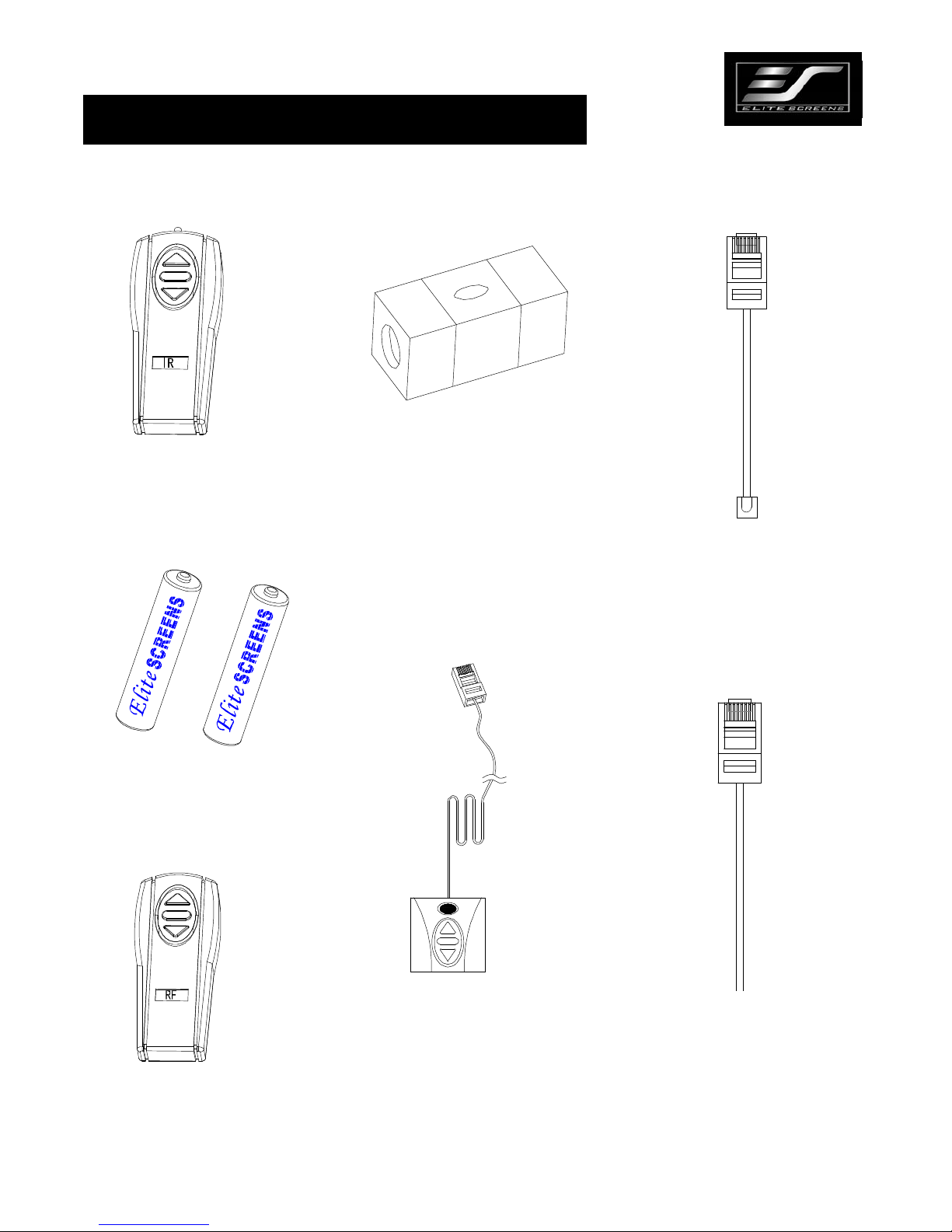
Accessory
IR
for Spectrum andVMAX2
Bubble level
Battery
Wallbox
(Opt
ional for Spectrum)
E ye receiver
(Optional for Spectrum)
Pleas e always point to the eye
receiver when u sing the IR remot e
Red 12V Green 0V
12V trigger cable
RF
for VMAX2 only)
ote: Contact your reseller for optional
accessories or visit shop.elitescreens.com
or accessory purchase.
Page 5

φ
φ
/
VMAX2 & Spectrum Series
IM PORTAN T S AF ETY INS TRUC TIONS
1. Position the power cord so it will not be; near a hot surface, pulled at or tripped over.
2. To avoid suffering an electric shock, do not attempt to disassemble this appliance yourself. In the event of technical
trouble, please contact Elite Screens service dept. for help with repairing your screen.
3. Please disconnect the power supply when screen is not in use for a long period of time as should be done with any other
electric household applianc e .
4. To avoid possible injury and/or an electric shock, do not attempt to use the screen if there is obvious damage or the
presence of broken parts.
PRE -I NSTAL LATION
1. Carefully unpack the screen.
2. Always handle the screen in a leveled position on a clean surface.
3. In order to protect the screen from exposure to stains, keep the screen out of contact with foreign particles such as dust,
sawdust and liquids.
Keyhole for flush mounting to
wall(R5 MM,R2 MM)
11m
Built-In IR Receiver for IR
remote (Point and Press Up /
Stop/Down)
Top key holes for ceiling
mounting(R3 MM,R2 MM)
6m
3-5/8” Height of
end cap
3-1/8” Width of
end cap
4”
3-3
4”
Page 6

proj
pp
g y
y
g y
)
g
g
g
g
proj
g
p
p
b
t
1. Select the location for your screen within a reasonable angle of projection for your home
ector and access to a good powersource.
2. For the best su
internal framework. If studs are not available, use hollow anchors for mountin
screws in dr
securin
ort of your screen, it is ideal to secure your screen into the studs of your house's
our wall-
wall or if you are installing in a concrete structure, use the concrete bolts for
our screen into concrete walls. (Always Consult Installer or Hardware Store for
t he correct screws
3. Make sure that the level in perfect horizontal alignmentwithone another. Use wall/ceilin
wood screws to secure to the woodstuds. Usehollow wall anchors ifmounting in drywall.
4. Position the washers to the head of the wall-screw. The washers
ive added stability by enablin
to remain firmly anchored to the wall.
5. The screen casin
is designed to accept the wall screws directly. If not using the Optional L-
bracket, be sure to position the washer between the head of the wall-screw and the anchor slots
on the
ector casing.
ardless of mounting method, screenshouldbesecurelysu
Re
a
usive pulling on th e viewing surface will notcause cas e to workloose or f all. Installer must
insur e tha
fasteners used are of adequate strength and suitable for the mounting surface chosen.
ortedsothat vibration or even
Page 7

p
a
1. Using a tape measure, mark the keyholes that are located at the back of the screen 's c ase end cap .
2. After marking the area and predrilled hole, insert the screw and leave about 1/8” of an inch from the wall to
mount the screen. (Fig. 1)
Fig. 1
O
tional installation using a chain to hang the screen from the ceiling.
Fig. 2.
3. You can also hang the screen from
ceilingbyusingachainwith s-hooks (not included) and hang
i t by th e keyholes located o n each end of the ca se as sho wn on (Fig. 2).
Page 8

r
g
Wood/Dry Wall installation: Use “B” wood
screws provided when purchasing the optional
L-brackets for installation on wood studs on
wall. Or use “E” hollow wall anchors in
conjunction with the wood screws for drywall
installation as shown on Fig. 1
Fig. 1
Fig. 2
Masonry/Cement wall
installation: If purchased the
optional L-brackets, use “D”
bolts for installing your screen
on a cement wall as shown on
Fig. 2.
Two options for you
installation
*Once the L-brackets are in place, the screen can be hun
Please note these are only examples and additional hardware may be required for your particular
installation. Also, the screen can be hung directly on the wall screws or bolts without using the L-brackets
at all.
from the vertical hooks.
Can
be slide free
Page 9

p
N
12-V Trigger
The VMAX2 and Spectrum Screens have the capability of using a 12-Volt Trigger. This accessory is
optional for Spectrum Screens and can be purchased separately.
To Projector
Red
Green 0V
DC12V
Video Projection Int erface
12-Volt Trigger Assembly
D i a g r a m A
Wa l l-mounted 3-way-switch
1. Bubble Level:
Included with the installation package is a
small bubble level that can be useful in determining if the
screen is
erfectly level when installing.
Bubble Level
2. Below is the RF remote with a range of 30 Ft.
(Radio Frequency)
Note: When you get the optional RF, you should
follow the instruction and adjust the code.
Diagram B
Infrared “Eye” Sensor with
IR Remote Control
3. Below is the IR remote (Infra Red) with a
range of 15 Ft.
(Infra Red)
ote: The light on this remote does not turn on
when the buttons are depressed unlike the RF
remote.
Radio Frequency Remote Control
Infrared Remote Control
Page 10

p
N
FAQ’S
1. Q: Why does my screen no longer function?
A: There are a few
A.) Make sure your wall plug has power and that the screen is properly plugged in.
B.) Please check the fuse to y our screen. (Call Tech support for location of fuse)
C.) If screen works well with the line switch but not with the remote control, make sure the remote control has good
batteries in it.
D.) Our electric screens with a tubular motor installed are equipped with a Thermal relay. This would include all
Home (2, 3), Tension (1, 2, 3) series, and VMAX screens with a diagonal size above 180". This feature will
automatically shut off screen in the event the motor becomes too hot, preventing overheating of the motor. To
correct this, let screen alone for 10-15 minutes and try again.
2. Q: How is the screen material cleaned?
A: The screen material can be cleaned with mild soap and water.
3. Q: What type of batteries do the remote controls require?
A: The IR and RF remote controls use AAA alkaline batteries
4. Q: Can you manually pull down the screen?
A: No, manually pulling down the screen will damage the electronic motor rolling system.
5. Q: How could I setup my Screens IR receiver to work with my learning remote control syste m? Do you have any IR
codes I can use to achieve this?
A: Our IR remote controls have been evaluated and entered in to the databases of some Universal remote control
manufacturers. Please contact the manufacturer of your remote to inquire about your remotes ability to function with ours.
If they have not evaluated our remote control then the following list of Binary codes will be used for most remote setups.
ossible things you could check:
For Spectrum, VMAX2 (Plus), Home2(3) and Tension2(3) Series
Up: 1111 0000 0001
Stop: 1111 0000 0010
Down: 1111 0000 0100
6. Q: What is the gain on the matte white screen material?
A: The matte white material has a gain of 1.1. For detailed specs, info please check our web-site for more detail
ote: For more Update FAQ, please visit www.elitescreens.com
Page 11

W
p
m
p
arranty Policy -Electric Screens
●
Two (2) year warranty parts and labor from purchase date as follows (except for refurbished units
as specified below):
●
Refurbished units carry a 90-day parts and labor warranty.
●
Demo units or open box items are AS IS items and do not carry a warranty.
●
Each party will be responsible for one way shipping during the warranty period.
●
DOA (Defective On Arrival): Must be reported within 7 business days of receipt. An RMA
(Return Merchandise Authorization) number must be issued in order to process a replacement. Elite
Screens will replace the DOA (Defective On Arrival) unit with a brand new replacement *(see
exceptions below) after the DOA unit is received and/or confirmed defective. Once the product is
received, Elite Screens will send out a new* unit to the customer by ground service (based on stock
availability). Should a problem be reported after the 7-day grace period, the item must be shipped to
us for warranty repair.
Missing Parts must be reported within the 7-day (DOA) grace period. If reported after 7 days,
●
customer will be only responsible for shipping and handling fees. If reported after 30 days of receipt,
customer is responsible for cost of the parts and shipping & handling fees.
Please visit link below for full warranty information
://www.elitescreens.com/service.ht
Htt
Please visit link below for warranty claim
Http://www.elitescreens.com/service_form.htm
*A new or refurbished replacement will be sent out to the customer depending on the type of
urchase (new or refurbished) or based on stock availability.
Page 12

Y
_
_ _________
_
_
_
_
_
_________
_ _____
y
___
_
_
_
_
_________
_ ___
___
_
_
_
_________
_
_
_
_ _ ___
_
_________
_ _ ___
_
___
_______
_
_
_
______
_
_
_____
_____
_
__
_
_ ___
_ _________
_
_ __
(
_____
_
_ __
y
__
_ _
_________
_ __
pp
__
_
_
_ _
____
____
__
_
y
___
__
_
__
_
__
_Imp
y
r
Two ways to registeryour warran tywith Elite Screens Inc.
A. On Line (Faster and Easier) www.elitescreens.com/register.htm
B. Fill out & Fax to (562) 483-8498, Attn: Customer Service Dept.
our Name: _ _
*
Address:
Cit
_
/State/Zip
*Email Address:
*Phone:
*Screen Model:
*Serial Number:
*Date of Purchase:
_
_
*Dealer / Reseller Purchased from
What is
A
our Projector Model:
lication:
Home
Education
Others
How would
ou rate this screen?
Comments:
nameofthe reseller):
Corporation
Excellent
Good
Government
Ok
rovement needed
ou have pictures of your screen you'd like to sharewith us, pleaseemail you r pictures to:
If
For any technical inquiries, please email to
techsupport@elitescreens.com
an y warrant y claim inquires, please email to
Fo
rma@elitescreens.com
or 877-511-12 11 Customer Service Div.
Eliteinfo@elitescreens.com
Orcallus at877-5 11-1211 Sales and
Marketing Div.
or 877-511-1211 Customer Service Div
 Loading...