

Page 1
Electric Wall/Ceiling Projection Screen
Saker Tab-Tension Series
User’s Guide
Important Safety & Warning Precautions
Make sure to read this user’s guide and follow the procedures below.
Caution: The screen’s Black Top Drop is already set to its maximum drop distance. There is NO extra
Black Top Drop in the roller. Please be aware of this as it will void your warranty with EliteProAV™.
Unapproved changes or modifications (except for cutting the power cord for hardwire installations) to this
unit are prohibited and will void your warranty. For more information, please contact our Technical Support
Department at (877) 511-1211 Ext. 604.
• Please retain this user’s guide for future reference.
• To avoid damaging the unit, do not use with any unauthorized accessories not recommended by the
manufacturer.
• Handle the unit carefully during transportation to avoid any damages.
• To ensure safe and reliable operation, direct connection to a properly grounded power source is
advised.
• The power outlet supplying power to the unit should be close to the unit and easily accessible.
• Do not install the unit on uneven or inclined surfaces.
• Do not put heavy objects on the power cord and position it properly to avoid creating a trip
obstacle.
• Never overload the power cord to prevent an electric shock or fire due to a loose contact or a short
circuit.
• There are not user serviceable parts in this unit. Do not attempt to disassemble this unit by yourself.
No one except authorized technicians can open and make repairs to this unit.
• Make sure the power source this unit is connected to has a continuous power flow.
• If there is need to use an extension cord, make sure the cord has an equal rating as the appliance to
avoid overheat.
• Do not handle the power plug when your hands are wet or your feet are in contact with water.
Do not use this unit under the following circumstances.
• Disconnect the power cord under the conditions of heavy rain, wind, thunder or lightning.
• Avoid direct Sunshine, rain shower and moisture.
• Keep away from fire sources and high temperature to prevent this device from overheating.
• Cut off the power supply first before transportation or maintenance.
• Fully disconnect from the power supply when the unit is not in use for a long period of time, as
should be done with any other electric household appliance.
• To avoid possible injury and/or an electric shock, do not attempt to use the screen if there is
obvious damage or if there are any evident broken parts.
Rev.042417-D 1 www.eliteproav.com
Page 2
WARNING
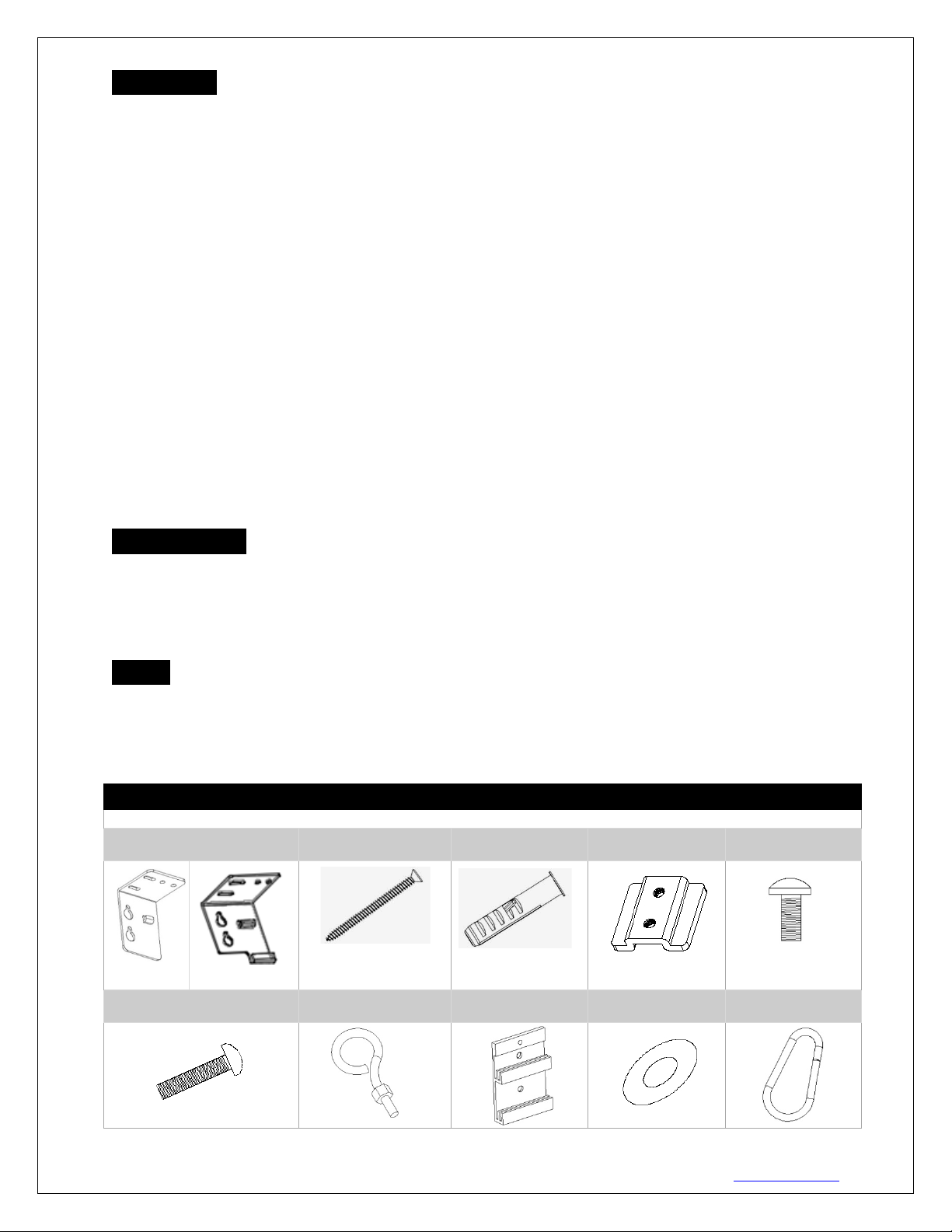
Hardware Parts List
Please make sure all parts listed below are included before proceeding with the installation.
A. Wall/Ceiling mount
bracket x2
B. M5x60 Screw x4
C. M12 Dry-wall
anchor x4
D.Bracket
connector x2
E. M5x11 Bolt
Screw x4
F. M5x25MM round head
cross screws x2
G. M5x30MM eyebolt
screw & M5 nut x2
H. Hidden wall
bracket x2
I. R18xR6x1
washer x4
J. Snap link x2
For 135” below For 135”-180”
The Screen’s Top Black Drop is already set to its maximum drop distance. There is NO extra top black
drop in the roller. Please be aware of this as it will void the limitation of your warranty.
Individual modifications to this product are prohibited and will void the warranty with the manufacturer.
Please contact EliteProAV™ Customer Service for any questions.
NOTE:
This equipment has been tested and found to comply with the limits for a Class B digital device, pursuant to
Part 15 of the FCC Rules.
These limits are designed to provide reasonable protection against harmful interference in a residential
installation. This equipment generates and can radiate radio frequency energy and, if not installed and used
in accordance with the instructions, may cause harmful interference to radio communications.
However, there is no guarantee that the interference will not occur on a particular installation. If this
equipment causes harmful interference to radio or television reception, which can be determined by turning
the equipment off and on, the user is encouraged to try to correct the interference by one or m ore of the
following measures.
Reorient or relocate the receiving antenn a o f the device wh ich may cause interference.
Increase the separation bet ween the scre en and the devic e’s recei ver.
Connect the equipment into a different power outlet other than the device.
Pre-Installation
1. Carefully unpack the screen.
2. Always handle the screen in a leveled position on a clean surface.
3. In order to protect the screen from exposure to stains, keep the screen out of contact with foreign
particles such as dust, sawdust, and/or liquids.
NOTE
Regardless of the mounting method, the screen should be securely supported so that the vibration or
pullin g on the vie wing surface will not cause the casing to become loose or fall. The installer must insure
that the fasteners used are of adequate strength and suitable for the installation location. Included mounting
screws are complimentary and may not be appropriate for all mounting surfaces. Use appropriate anchors to
safely secure the screen to the mounting surface or consult with a professional installer.
Rev.042417-D 2 www.eliteproav.com
Page 3
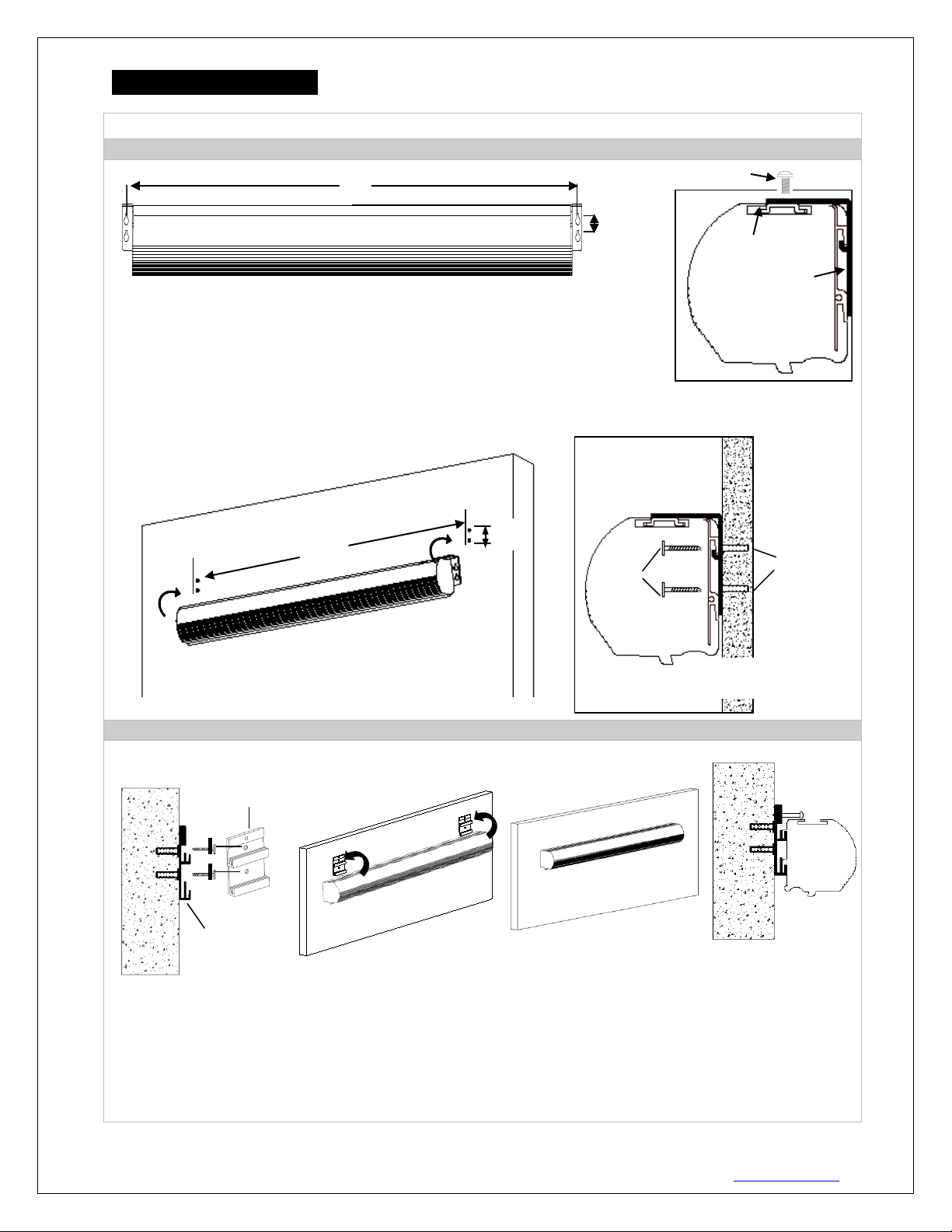
Installation Instruct ions
A. Wall Mount
I.Flush mount with wall/ceiling brackets (fixed position)
II. Flush hidden mount (movable position)
This mount method allows the screen to slide horizontally.
5. Last ly, screw the M5 screw (F) into the upper hole of the bracket to add additional support for the screen.
W
H
Bracket connector
M5x11 Bolt Screw
M5x60
Wall
Dry-wall
anchors (C)
H
W
Wall
Front view of bracket (h)
Side view of
bracket (h)
For installation assistance, please consult a professional Installer. EliteProAV™ is not liable for faulty installations.
1. Begin by sliding the bracket connector (D) all the way to each end of the housing.
2. Then attach it to the wall/ceiling mount bracket (A) wit h the M5x11 bolt screw (E).
3. Measure and mark the (WxH) distance between the two holes on each bracket.
4. Drill a hole for each screw hole on the marked areas.
5. Insert a dry-wall anchor (C) into the wall.
6. Insert aM5x60 Screw (B) in each dry-wall anchor (C) and screw it in leaving about 1/8” of an inch.
7. Hang the screen by aligning the end cap holes to the M5x60 screws (B).
screws (b)
(D)
Wall/Ceiling Mount
Bracket (A)
1. Determine where the screen will be installed. Then, measure and mark the distance between the top and bottom
screw holes from each hidden wall mount bracket (H).
2. Drill a hole on all marked areas and install the brackets with the dry-wall anchor(C), M5x60 screw (B), and a
washer (I). Make sure both brackets are properly leveled.
3. Hang the screen by placing the downward “catch “located on the back over the brackets upper “catch”.
4. After making sure the screen is secured, you can slide it left / right to pro perly center it in position.
Rev.042417-D 3 www.eliteproav.com
Page 4

B. Ceiling Mount
I. Ceiling Mount(fixed position on end caps)
Two or more people are required while one holds the screen in place.
II. Suspended
1. Screw the eyebolt (G) on the bracket connector (D).
H
W
Dry-wall anchors (C)
M4x50 screw (B)
Ceiling
Washer (I)
NOTE: The brackets do not slide. They are designed to attach the end caps only.
1. Attach the Wall/Ceiling mount bracket (A) to the Bracket connector (D) located on top of the screen’s housing (preinstalled).
2. Determine where the screen will be installed. Then, measure and mark the distance between the (WxH) locations.
3. Drill a hole on all marked areas and insert a dry-wall anchor(C).
4. Secure the screen by inserting the M5x60 screw (B) and a washer (I) thru the wall/ceiling mo unt brackets (A).
2. Attach the snap link (J) through the eyebolt (G) and connect it to an eyebolt screw (not included) rated
for the screen’s weight.
Screen mate rial te ns i on adjustment (4mm Allen Wrench required and not included)
Remove the weight bar end cap to expose the adjustment tension knob. Insert your 4mm Allen Wrench to
push in the adjustment tension knob, turn clockwise and your screen will gain more tension. Turn the Allen
Wrench counter clockwise and the screen will lose tension. Please note this adjustment is not necessary as
the tension of the screen has been set to its factory setting for best performance. Please contact
EliteProAV™ for assistance to avoid damaging the screen and voiding your warranty.
Rev.042417-D 4 www.eliteproav.com
Page 5

Saker Tab-Tension Series | Controls and Accessories
A. IR Remote
B. RF Remote
C. Wall switch control box
D. 5-12 volt trigger cable
E. IR extended “eye” receiver
F. Wireless 5-12v trigger cable
G. AAA batteries
H. Bubble leveler
6 ways to control your Saker Tab-Tension
1. IR remote control (Item A, Fig 1): The Infrared functions by direct line
Fig.2
Fig.3
UP
IR “eye” receiver
3 Way Wall Switch
Fig.1
IR/RF remote
4. 3-Way Wall Switch (Item C, Fig 3): The 3-way wall switch
Screen operation
Electric Current: Depending upon region, your EliteProAV™ screen will operate on 100v, 110v or 220v
voltage.
1. After ensuring the power outlet & screen are compatible (voltage), plug the power co rd into the power outlet.
2. Once the screen has power, you’ll be able to control it using any of the 6 methods described below.
of sight contact with a beam range of 30 feet. Aim the IR remote at the
circular window located on the left side of the screen.
2. IR “Eye” Receiver (Item E, Fig 2): The IR “Eye” Receiver plugs
directly into the screen’s RJ-45 input to present a low profile line-of-sight
control option for your IR remote control even in a recessed ceiling
installation.
3. RF Remote Control (Item B ): The radio waves eliminate the need for a
direct line of sight with a range of 100 feet.
is a wall mount control box with an up/stop/down button and
plugs directly into the screen’s RJ-45 input.
(does not have IR sensor)
STOP
DOWN
Rev.042417-D 5 www.eliteproav.com
Page 6

6. Wireless 5-12 volt trigger (Ite m F, Fig 5): The RF remote control serves as a dual purpose, independently as a
5. 5-12 volt trigger (Item D, Fig 4): The built-in 5-
12 volt RJ45 cable connects to your
the projector. The trigger feature will not work
DC 5-12V out
Wireless 5-12V
The back of the
Fig.4
3 prong power cord
RJ45 Input
5-12 volt trigger cable
Fig 5
12V trigger input allows your screen to synchronize
its drop & rise with the projector’s power cycle.
The screen deploys when the projector powers up
and will retract when the projector powers down.
The 5projector’s trigger output via a separate cable that
may or may n ot be pr o vid ed b y the man uf ac tur er of
without an output cable from the projector, but it
can be tested by connecting the Red (+) and Green
(-) cable to a 9-volt battery.
handheld remote control, or in conjunction with the Wireless 5-12 volt trigger cable. The radio frequency
technology can be programmed to send a wireless signal to synchronize its drop & rise with the projector’s power
cycle.
Here’s how to set up your Wireless 5-12 volt trigger | Synchronization Instructions
Step1: Connect one end of the 3.5 mm wireless 5-12 volt trigger cable to the RF remote.
Step 2: Connect the other 3.5 mm end of the wireless 5-12 volt trigger cable to your projector
Step 3: Make sure to unplug your screen from the power outlet
Step 4: Hold the UP button on your RF remote
Step 5: While holding the UP button, plug the screen back to the power outlet
Step 6: Wait 5 seconds and then release the UP button
Step 7: Your 5-12V wireless trigger should now be activated with your screen and ready to be used and able to
control your screen with your projector’s power cycle
Repeat the steps again if not successful.
(Please be aware, the projector on/off cycle may take longer to fully activate. It usually takes around 20-
30seconds for full off and on cycle each time)
projector
Rev.042417-D 6 www.eliteproav.com
trigger cable
UP
St op
Down
Page 7

Dimension s Table
Note: Data Error ±1"
Model
Numbers
SKT100XVW-E10 98.4 80.0 97.6 96.6 65.1 89.4 94.0 4.7 76.6 60.0 72.4 10.0 2.4 3.9 4.0 4.3 1.4 0.9
SKT120XVW-E9 116.2 96.0 115.4 114.4 82.9 105.4 111.8 4.7 87.6 72.0 83.4 9.0 2.4 3.9 4.0 4.3 1.4 0.9
SKT84XHW-E12 91.8 73.2 91.0 90.0 58.5 81.1 87.4 3.9 59.8 41.2 55.6 12.0 2.4 3.9 4.0 4.3 1.4 0.9
SKT100XHW-E12 105.7 87.2 105.0 103.9 72.4 95.0 101.4 3.9 67.6 49.0 63.4 12.0 2.4 3.9 4.0 4.3 1.4 0.9
SKT110XHW-E24 116.2 95.9 115.4 114.4 82.9 105.3 111.8 4.7 84.6 53.9 80.3 24.0 2.4 3.9 4.0 4.3 1.4 0.9
SKT120XHW-E20 124.8 104.6 124.1 123.0 91.5 114.1 120.5 4.7 85.4 58.8 81.2 20.0 2.4 3.9 4.0 4.3 1.4 0.9
SKT135XHW-E6 139.4 117.7 138.6 137.6 106.1 127.1 135.0 4.7 78.8 66.2 74.5 6.0 2.4 3.9 4.0 4.3 1.4 0.9
SKT150XHW-E6 153.1 130.7 151.7 150.4 118.9 139.4 148.0 4.3 86.8 73.5 81.9 6.0 2.4 4.6 4.6 4.9 1.4 0.9
SKT165XHW-E6 166.4 143.8 165.0 163.6 132.1 153.3 161.3 4.7 94.2 80.9 89.3 6.0 2.4 4.6 4.6 4.9 1.4 0.9
SKT106NXW-E12 108.3 89.9 107.5 106.5 75.0 97.8 103.9 3.9 74.8 56.2 70.6 12.0 2.4 3.9 4.0 4.3 1.4 0.9
SKT120NXW-E12 121.9 101.8 121.1 120.1 88.6 111.2 117.5 4.7 82.2 63.6 78.0 12.0 2.4 3.9 4.0 4.3 1.4 0.9
SKT100UH-E24-AUHD 105.7 87.2 105.0 103.9 72.4 95.0 101.4 3.9 79.6 49.0 75.4 24.0 2.4 3.9 4.0 4.3 1.4 0.9
SKT110UH-E24-AUHD 116.2 95.9 115.4 114.4 82.9 105.3 111.8 4.7 84.6 53.9 80.3 24.0 2.4 3.9 4.0 4.3 1.4 0.9
SKT120UH-E20-AUHD 124.8 104.6 124.1 123.0 91.5 114.1 120.5 4.7 85.4 58.8 81.2 20.0 2.4 3.9 4.0 4.3 1.4 0.9
SKT135UH-E12-AUHD 140.0 117.7 138.6 137.3 105.8 127.1 134.9 4.7 85.5 66.2 80.6 12.0 2.4 4.6 4.6 4.9 1.4 0.9
SKT150UH-E12-AUHD 153.1 130.7 151.7 150.4 118.9 140.2 148.0 4.7 92.8 73.5 87.9 12.0 2.4 4.6 4.6 4.9 1.4 0.9
SKT180UH-E3-AUHD 179.3 156.9 177.8 176.5 145.0 167.1 174.1 5.1 98.5 88.3 93.6 3.0 2.4 4.6 4.6 4.9 1.4 0.9
SKT100XVW-E10 2499 2032 2479 2453 1653 2272 2388 120 1946 1524 1838 254 60 100 102 108 35 23
SKT120XVW-E9 2951 2438 2931 2905 2105 2678 2840 120 2226 1829 2118 229 60 100 102 108 35 23
SKT84XHW-E12 2331 1860 2311 2285 1485 2060 2220 100 1519 1046 1411 305 60 100 102 108 35 23
SKT100XHW-E12 2686 2214 2666 2640 1840 2414 2575 100 1718 1245 1610 305 60 100 102 108 35 23
SKT110XHW-E24 2951 2435 2931 2905 2105 2675 2840 120 2148 1370 2040 610 60 100 102 108 35 23
SKT120XHW-E20 3171 2657 3151 3125 2325 2897 3060 120 2170 1494 2062 508 60 100 102 108 35 23
SKT135XHW-E6 3541 2989 3521 3495 2695 3229 3430 120 2001 1681 1893 152 60 100 102 108 35 23
SKT150XHW-E6 3889 3321 3853 3819 3019 3541 3759 110 2205 1868 2080 152 60 118 118 125 35 23
SKT165XHW-E6 4227 3653 4191 4155 3355 3894 4097 119 2393 2055 2268 152 61 117 117 124 36 23
SKT106NXW-E12 2751 2283 2731 2705 1905 2483 2640 100 1900 1427 1792 305 60 100 102 108 35 23
SKT120NXW-E12 3096 2585 3076 3050 2250 2825 2985 120 2088 1615 1980 305 60 100 102 108 35 23
SKT100UH-E24-AUHD 2686 2214 2666 2640 1840 2414 2575 100 2022 1245 1915 610 60 100 102 108 35 23
SKT110UH-E24-AUHD 2951 2435 2931 2905 2105 2675 2840 120 2149 1370 2040 610 60 100 102 108 35 23
SKT120UH-E20-AUHD 3171 2657 3151 3125 2325 2897 3060 120 2170 1494 2062 508 60 100 102 108 35 23
SKT135UH-E12-AUHD 3557 2989 3521 3487 2687 3229 3427 120 2171 1681 2046 305 60 118 118 125 35 23
SKT150UH-E12-AUHD 3889 3321 3853 3819 3019 3561 3759 120 2358 1868 2233 305 60 118 118 125 35 23
SKT180UH-E3-AUHD 4553 3985 4517 4483 3683 4245 4423 130 2503 2242 2378 76 60 118 118 125 35 23
A A1 A2 A3 A4 A5 A6 A7 B B1 B2 B3 B4 B5 C C1 C2 C3
Unit: Inches
Unit: mm
Rev.042417-D 7 www.eliteproav.com
Page 8

For the following videos please visit:
Flush Wall Mount Installation video –
Flush Ceiling Mount Installation video -
Wall Installation Video Ceiling Installation Video –
Wireless Trigger Demonstration Video -
www.elitescreens.com/sakertabwallinstall
www.elitescreens.com/sakertabceilinginstall
www.elitescreens.com/sakerflushwallinstall
www.elitescreens.com/sakerflushceilinginstall
www.elitescreens.com/sakertabtriggerdemo
For more information, technical support or your local EliteProAV™ contact, please
www.eliteproav.com
visit
Rev.042417-D 8 www.eliteproav.com
 Loading...