

Page 1
MZ04242018 1 www.elitescreens.com
Electric Wall/Ceiling Projection Screen
Saker Tab-Tension Series
User’s Guide
Important Safety & Warning Precautions
Make sure to read this user’s guide and follow the procedures below.
Caution: The screen’s Black Top Drop is already set to its maximum drop limit. There is NO extra black-
matte drop material on the roller. Please be aware that altering the vertical limit switch to drop the screen
material off the roller voids your warranty with Elite Screens®. Unapproved changes or modifications (except
for cutting the power cord for hardwire installations) to this unit are prohibited and will likewise void your
warranty.
For more information, please contact our Technical Support Department at (877) 511-1211 Ext. 604.
• Please retain this user’s guide for future reference.
• To avoid damaging the unit, do not use with any unauthorized accessories not recommended by the
manufacturer.
• Handle the unit carefully during transportation to avoid any damages.
• To ensure safe and reliable operation, make sure the power connection is secure.
• The power source should be close to the unit and easily accessible.
• Do not install the unit on uneven, or inclined surfaces;
• To avoid electrical shock or product damage, do not install this device in a damp place.
• Do not place any heavy objects over the power cord.
• Position the power cord properly to avoid creating a trip hazard.
• Avoid electrical shock or fire, by not overloading the power cord.
• The internal & external parts of this unit are not end user serviceable. Do not attempt to
disassemble this unit by yourself. Consult an authorized technician instead.
• Make sure the power source that this unit is connected to has a continuous power flow.
• If there is need to use an extension cord, make sure said cord has a compatible power rating.
• Do not handle this or any other electrical device if you are wet or standing in water.
• Whenever the screen reaches its end of life, follow local environmental guidelines regarding its
proper disposal.
Do not use this unit under the following circumstances.
• Disconnect the power cord if exposed to moisture, rain, wind, electrical storms or snow.
• Avoid exposure to direct sunlight or any of the conditions stated in the previous bullet point.
• Keep away from fire or other high temperature heat sources.
• Cut off the power supply first before attempting maintenance or removal.
• Do not attempt to use this screen if there are obvious signs of damage.
• To avoid possible injury and/or an electric shock, do not attempt to use the screen if there is
obvious damage or if there are any evident broken parts.
Page 2
MZ04242018 2 www.elitescreens.com
WARNING
Individual modifications to this product are prohibited and will void the manufacturer’s warranty. Please
contact the Elite Customer Service Team with any questions.
NOTE:
This equipment has been tested and found to comply with the limits for a Class B digital device, pursuant to
Part 15 of the FCC Rules.
The product settings are designed to provide reasonable protection against any radio interference within a
residential installation. If properly installed, the Saker Tab-Tension screen may suffer from RF interference
from other home electronics.
Although radio interference affecting other household electronics is unlikely, the following steps can be
taken should RF interference occur.
✓ Reorient or relocate the receiving antenna on the device that may be casing the interference.
✓ Increase the distance between the screen and the interfering device’s receiver.
✓ Connect the projection screen to another power source apart from the interfering device.
Pre-Installation
1. Carefully unpack the screen.
2. Always handle the screen upright on a clean, level surface.
3. Keep the screen out of contact with foreign particles such as dust, sawdust, and/or liquids.
NOTE
Regardless of the mounting method, each screen should be securely installed so that vibrations or pulling
on the viewing surface will not cause the casing to become loose or fall. Included are complimentary
mounting screws that may or may not be appropriate for the installation you are attempting. Always use the
correct anchors to safely secure the screen and always consult a professional integrator.
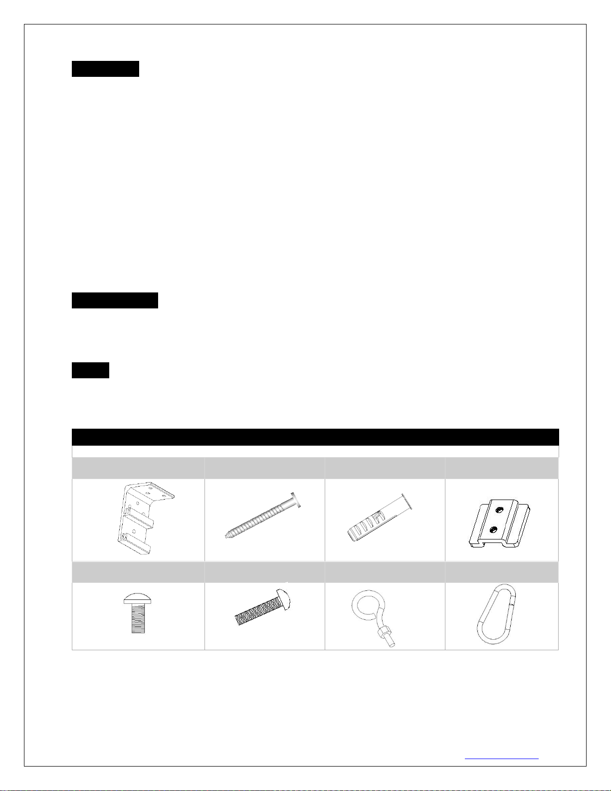
Hardware Parts List
Please make sure all parts listed below are included before proceeding with the installation.
A. Wall/Ceiling mount bracket
x2
B. M5x60 Screw x6
C. M12 Dry-wall anchor x6
D. Bracket connector x2
(Installed on the housing)
E. M5x11 Bolt Screw x4
(Screw on the D parts)
F. M5x25MM round head
cross screws x2
G. M5x30MM eyebolt screw
& M5 nut x2
H. Snap link x2
Page 3

MZ04242018 3 www.elitescreens.com
Installation Instructions
For installation assistance, please consult a professional Installer. EliteScreens is not liable for faulty installations.
A. Wall Mount
Flush hidden mount (movable position)
This mount method allows the screen to slide horizontally.
1. Determine where the screen will be installed. Then, measure and mark the distance between the top and
bottom screw holes from each Wall/Ceiling mount bracket (A).
2. Drill a hole on all marked points and install the brackets with the dry-wall anchor(C), M5x60 screw (B),
Make sure both brackets are properly leveled.
3. Hang the screen by placing the lower “catch” located on the back over the brackets upper “catch”.
4. After making sure the screen is secured, you can slide it left / right to properly center it in position.
5. Lastly, screw the M5 screw (F) into the upper hole of the bracket to add additional support for the screen.
Two or more people are required while one holds the screen in place.
B. Ceiling Mount
I.Ceiling Mount (movable position)
This mount method allows the screen to slide horizontally.
1. Determine where the screen will be installed. Then, measure and mark the distance between the top and
bottom screw holes from each Wall/Ceiling mount bracket (A).
2. Drill a hole on all marked areas and install the brackets with the dry-wall anchor(C), M5x60 screw (B),
Make sure both brackets are properly leveled.
3. Hang the screen by placing the lower “catch” located on the back over the bracket’s upper “catch”.
4. After making sure the screen is secured, you can slide it left / right to properly center it in position.
5. Lastly, screw the M5 screw (F) into the upper hole of the bracket to add additional support for the screen.
Two or more people are required while one holds the screen in place.
Side view of
Front view of bracket (A)
M5x25MM round
head cross screws
(F)
Front view of
bracket (A)
Side view of
bracket (A)
M5x25MM
round head
cross screws (F)
Ceiling
Page 4

MZ04242018 4 www.elitescreens.com
II. Suspended
1. Screw the eyebolt (G) onto the bracket connector (D).
2. Attach the snap link (H) through the eyebolt (G) and connect it to the ceiling eyebolt screw (not included)
as rated for the screen’s weight.
Screen material tension adjustment (4mm Allen Wrench required and not included)
Remove the weight bar end cap to expose the adjustment tension knob. This knob has a 4mm Allen port.
Insert your 4mm Allen Wrench and push in the adjustment tension knob, turn clockwise and your screen will
gain more tension. Turn the Allen Wrench counter clockwise and the screen will lose tension. Please note
this adjustment is not necessary as the tension of the screen has been pre-set to its factory drop setting. If you
would like to adjust the screen tension, please contact Elite Screens® for assistance to avoid damaging the
screen and voiding your warranty.
Saker Tab-Tension Series | Controls and Accessories
A. IR Remote
B. RF Remote
C. Wall switch control box
D. 5-12 volt trigger cable
E. IR extended “eye” receiver
F. Wireless 5-12v trigger cable
G. AAA batteries
H. Bubble leveler
Ceiling
Page 5

MZ04242018 5 www.elitescreens.com
Screen operation
Electric Current: Depending upon region, your Elite Screen will operation 100v, 110v, or 220v voltage.
1. After ensuring the power outlet & screen are compatible (voltage), plug the power cord into the power outlet.
2. Once the screen has power, you’ll be able to control it using any of the 6 methods described below.
6 ways to control your Saker
1. IR remote control (Item A, Fig 1): The Infrared
functions by direct line of sight contact using a beam
range of 30 feet. Aim the IR remote at the circular
window located on the left side of the screen.
2. IR “Eye” Receiver (Item E, Fig 2): The IR “Eye”
Receiver plugs directly into the screen’s RJ-45 input
to present a low-profile line-of-sight control option for
your IR remote control. It is an extended eye-receiver
to accommodate a recessed ceiling installation..
3. RF Remote Control (Item B): The radio waves
eliminate the need for a direct line of sight and has a
range of 100 feet.
4. 3-Way Wall Switch (Item C, Fig 3): The 3-way wall
switch is a wall mounted control box with an
up/stop/down button. It plugs directly into the screen’s
RJ-45 input.
5. 5-12 volt trigger (Item D, Fig 4): The built-in 5-12V
trigger input allows your screen to synchronize its drop
& rise with the projector’s power cycle. The screen
deploys when the projector powers up and will retract
when the projector powers down. The 5-12 volt RJ45
cable connects to your projector’s trigger output via a
separate cable that may or may not be provided by the
manufacturer of the projector. The trigger feature will
not work without an output cable from the projector,
but it can be tested by connecting the Red (+) and Green
(-) cable to a 9-volt battery.
6. Wireless 5-12 volt trigger (Item F, Fig 5): The RF
remote control serves as a dual purpose, independently
as a handheld remote control, or as a Wireless 5-12 volt
trigger using the trigger cable. The radio frequency
technology can be programmed to send a wireless
signal that synchronizes screen drop & rise with the
projector’s power cycle.
Fig.2
UP
STOP
DOWN
Fig.1
IR/RF remote
IR “eye” receiver
Fig.3
3 Way Wall Switch
Page 6

MZ04242018 6 www.elitescreens.com
UP
St op
Down
Here’s how to set up your Wireless 5-12 volt trigger | Synchronization Instructions
Step1: Connect one end of the 3.5 mm wireless 5-12 volt trigger cable to the RF remote.
Step 2: Connect the other 3.5 mm end of the wireless 5-12 volt trigger cable to your projector
Step 3: Make sure to unplug your screen from the power outlet
Step 4: Hold the UP button on your RF remote
Step 5: While holding the UP button, plug the screen back to the power outlet
Step 6: Wait 5 seconds and then release the UP button
Step 7: Your 5-12V wireless trigger should now be activated with your screen and ready to be used and able
to control your screen with your projector’s power cycle
Repeat the steps again if not successful.
(Please be aware, the projector on/off cycle may take longer to fully activate. It usually takes around 2030seconds for full off and on cycle each time)
For the following videos please visit:
• Ceiling Installation Video – www.elitescreens.com/sakertabceilinginstall
• Wireless Trigger Demonstration Video - www.elitescreens.com/sakertabtriggerdemo
For more information, technical support or your local EliteScreens® contact,
please visit www.elitescreens.com
DC 5-12V out
Wireless 5-12V
trigger cable
The back of the
projector
Fig 5
3 prong power cord
Fig.4
RJ45 Input
5-12 volt trigger
 Loading...