

Elite Screens isf CineWhite UHD-B Sable Frame B2 Series User Manual

REV040819BR-Z www.elitescreens.com
1
Sable Frame B2 Series
CineWhite® UHD-B (Matte White) Fixed Frame Projection Screen
USER’S GUIDE
Thank you for choosing an Elite Screens fixed frame projection screen! Congratulations on your new Sable Frame B2 purchase! Please read
through this user guide before utilizing the screen. Correct usage and maintenance will ensure a long product life. The front projection material
CineWhite® UHD-B is ISF Certified for accurate color reproduction in a controlled room environment.
Care & Use Instructions
Dust, dirt and scratches on the projection surface will affect the picture quality, please take note of the points below to prevent that from
occurring:
1. Do not touch the projection surface with your hands
2. Do not write or draw on the projection surface
3. Do not use fingers or sharp objects to point on the projection surface; this will damage the screen material.
4. Use a soft-damp cloth to clean the projection surface; do not use chemical cleaning agents or alcohol.
5. Use clean water when dampening the cleaning cloth and do not rub against the material to clean it.
.
Frame Parts List
A. Vertical Frame x 2 pcs
B. ½ Horizontal Frame x 2 pcs
C. ½ Horizontal Frame x 2 pcs
Hardware Parts List
A.
B.
C.
D.
E.
F.
G.
H.
I. J.
CAUTION: The screen should be assembled in a temperature range from 68°-78° F (20°-
26° C).
Overstretching the screen material in a temperature belo w the recommended range can cause permanent
damage including ripping and/or tearing which is not covered under warranty.
A
C + B
B + C
A
REV040819BR-Z www.elitescreens.com
2
Note: Additional spare parts may be included.
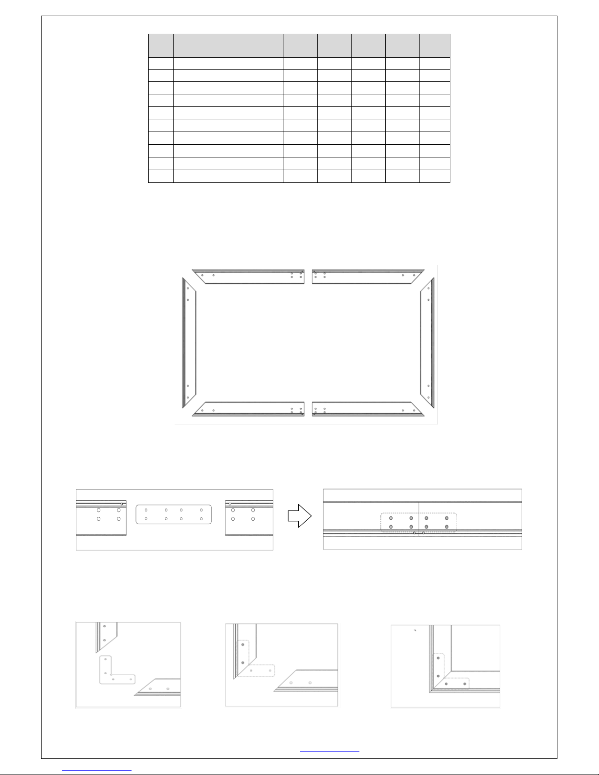
Assembly
Step 1. Place a soft-clean cloth on the ground or other flat surface of the area where the screen will be assembled.
Step 2. Position the pieces of the frame face-down on the soft-clean cloth in the arrangement shown below.
Step 3. Insert the Center Joint (A) connector into one-half of the Horizontal Frame (B) and fasten with two Large Screws and Washers (D).
Once secure, connect with the one-half of the Horizontal Frame (C) and fasten with two Large Screws and Washers (D). Repeat steps for the
other one-half of Horizontal Frames (B) and (C).
Step 4. Insert the Elbow Joints (C) to top and bottom sections of the Vertical Frame (A). Once inserted, secure the Elbow Joints (C) by fastening
them with the Large Screws and Washers (D) and connect the Vertical Frame sections to the Horizontal Frame sections. Make sure all corner
frames pieces are flush (no gaps). They should form perfect right angles.
Do not tighten the Screws firmly until all frame pieces are assembled correctly.
Item Parts List
100”
Screen
110”
Screen
120”
Screen
135”
Screen
150”
Screen
A.
Center Joints 2 2 2 2 2
B.
Springs
54
56
58
62
68
C.
Elbow Joints 4 4 4 4 4
D.
Large Screw/Washer/Small Screw
32/32/4
32/32/4 32/32/4 32/32/4 32/32/4
E.
Pull Hook
1
1 1 1 1
F.
Wall Bracket 2 2 2 2 2
G.
Drywall anchor/Screw/Washer
4/4/4
4/4/4
4/4/4
4/4/4
4/4/4
H.
Short/Long Tension Rods
2/4 2/4 2/4 2/4 2/4
I.
Center Support Bar
1 1 1 1 1
J.
Tension Rod Cap
8 8 8 8 8
Note: You may have to loosen and adjust the brackets and frame pieces. It will help to leave the screws loose until perfect right angles
are formed, then tighten the screws securely.
 Loading...