

Page 1

ezFrame CineGrey 5D™
Ambient Light Rejecting Fixed Frame Screen
USER’S GUIDE
Congratulations on your new ezFrame purchase! The screen material included is our award winning
CineGrey 5D™ which is a front projection material, precisely formulated for environments with minimal control
over room lighting. It was designed to enhance picture brightness, offer accurate color fidelity, and improve
contrast levels. The CineGrey 5D™ is best for family rooms, educational facilities, conference rooms, house of
worship or any applications in which incident light is a factor.
In order for the CineGrey 5D™ to maintain its projection qualities and optimum performance please refer to the
list below for proper maintenance and cleaning.
Use a dry microfiber cloth to remove dust from the screen’s surface.
When cleaning, use a damp microfiber cloth with warm water to remove any marks.
Never rub or apply pressure when cleaning the surface.
Never attempt to use any solutions, chemicals or abrasive cleaners on the screen surface.
In order to avoid damaging the screen, avoid touching it directly with your fingers, pens/pencils or any
other sharp or abrasive objects.
Assembly Video
Watch our assembly video on-line at
www.elitescreens.com/video/ezframeCG5D
or scan the QR code
05/17/16-DR www.elitescreens.com 1
Page 2
f. g. h. i. j.
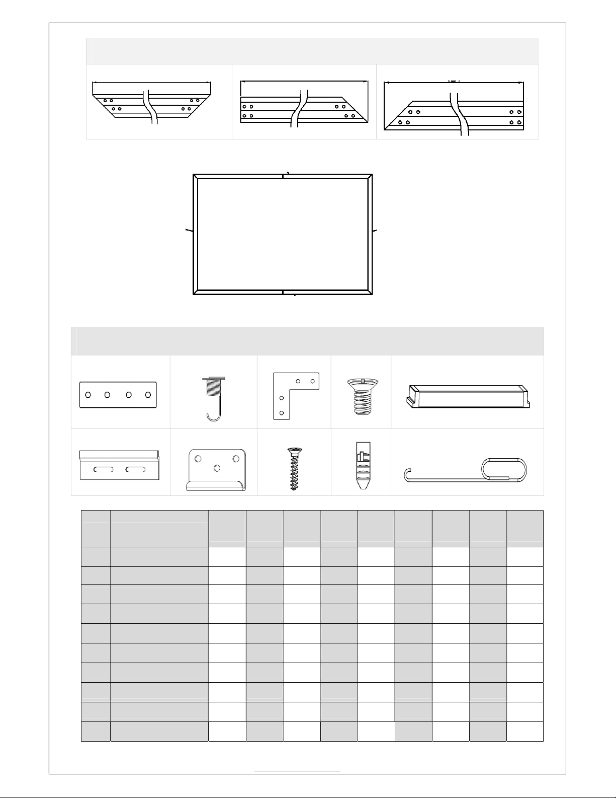
Frame Parts List
A
A. Vertical Frame x 2pcs B. ½ Horizontal Frame x2 pcs C. ½ Horizontal Frame x 2 pcs
A
B+C
C+B
Hardware Parts List
a. b. c. d. e.
Item
a. Center Joints 4 4 4 4 4 4 4 4 4
b. Spring 76 86 92 98 108 120 134 160 178
c. Elbow Joints 8 8 8 8 8 8 8 8 8
d. Screws M4x6 48 48 48 48 48 48 48 48 48
e. Center Support Bar 1 1 1 1 1 1 1 2 2
f. Top hanging brackets 2 2 2 2 2 2 2 2 2
Parts List
84”
Screen
92”
Screen
100”
Screen
110”
Screen
120”
Screen
135”
Screen
150”
Screen
180”
Screen
200”
Screen
05/17/16-DR www.elitescreens.com 2
g. Bottom brackets 2 2 2 2 2 2 2 2 2
h. Wall Screws M5x50
i. Hollow Wall anchors
j. Pull Hook 2 2 2 2 2 2 2 2 2
8 8 8 8 8 8 8 8 8
8 8 8 8 8 8 8 8 8
Page 3
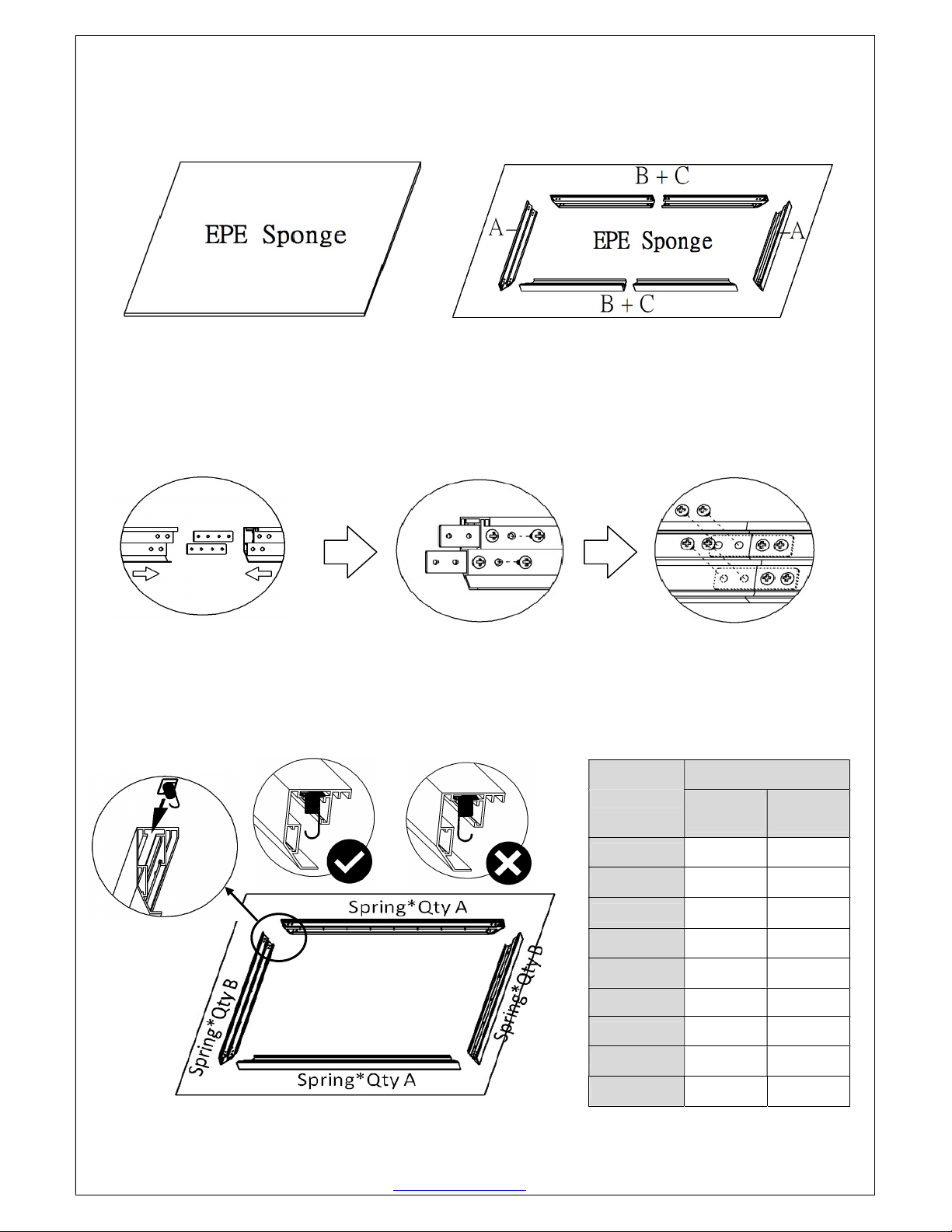
Frame Assembly
Step 1. Place a soft-clean cloth on the ground of the area where the screen will be assembled.
Step 2. Position the pieces of the frame on the soft-clean cloth in the arrangement shown below.
Step 3. Insert the center joint connectors into one-half of the horizontal frame and secure with the
M4x6 screws (2 for both top and bottom). Once secure, connect the other half of the horizontal frame
and fasten with the M4x6 screws (2 for both top and bottom).
Step 4. Insert the springs into the grooves of the frame. The spring hooks should be facing the front
side of the frame. For the correct amount of springs to place into the frame, please refer to the table
listed below.
Qty
Screen Size
A
(Spring)
B
(Spring)
84”
92”
100”
110”
120”
24 14
27 16
29 17
31 18
34 20
05/17/16-DR www.elitescreens.com 3
135”
150”
180”
200”
38 22
42 25
51 29
57 32
Page 4

Step 5. Connect the elbow joints to top and bottom sections of the vertical frame. Once inserted,
connect the vertical sections to the horizontal frame sections. Make sure all the holes are in alignment
and the frames pieces are flush (no gaps). They should form perfect right angles.
Step 6. Secure the elbow joints by fastening them with 4 M4x6 screws (4 at each corner). Do no tighten
completely until all frame pieces are assembled correctly.
Step 7. Carefully unroll the screen material from the roller from one side of the frame to the other side as shown
below.
Front Side
Step 8. With one end of the spring and secure inside the groove of the frame, hook the spring to the hole located
on the screen material’s outer edge. Use the pull hook when necessary. Attach the four corners first (1). After
those are secure, connect the vertical portions of the material, begin in the center and move towards the corners
(2). Lastly, connect the horizontal sections of the material by connecting the center of the material and make your
way towards the corners (3).
05/17/16-DR www.elitescreens.com 4
Page 5

Step 9. Insert the Center Support Bar into the upper top groove on the back of the frame (not the one where the
spring inserts) with the bottom end near the approximate center point of the frame. Rotate it in at an angle so that
both ends of the bar are in alignment with the groove. (See illustrations below for details)
Diagonal Models 150” and below use
1 x Center Support Bar
Diagonal Models above 150” require
2 x Center Support Bars
05/17/16-DR www.elitescreens.com 5
Page 6

Notice to Installer:
Please use the following installation instructions to obtain superior optical performance from the
CineGrey 5D™ Angular Reflective ALR (Ambient Light Rejecting) Screen.
Make sure to follow these instructions in order for the CineGrey 5D™ to perform correctly.
•Angular-Reflective material is not compatible with ultra/short-throw projectors
•Minimum lens throw ratio 1.5x image width
•Ambient light must not come from the same direction as the projector
Since angular-reflective means that the projected image will reflect at the mirror-opposite
angle, it is important to position the projector so that the viewer will get the best possible
image.
Step 1: Establish the general “eye level” of the viewers
Step 2: Set the appropriate projection level
Step 3: Adjust the screen height level and projection angle
Input Angle (A) = Output Angle (B) aligns with the viewer’s angle
05/17/16-DR www.elitescreens.com 6
Page 7

Installation
Step 10. Measure the overall length and height of the frame and drill holes for the top brackets. Line up the wall
brackets with the drilled holes on the installation location and screw them in using a Phillips screwdriver. If not
installing into a structural wood stud, use a hollow wall anchor then screw in the M5x50 wood screws with a
screwdriver. Make sure the brackets are leveled.
Step 11. Position the fixed frame screen onto the top wall brackets as shown below and push down at the center
of the top of the frame to secure.
Step 12.With the frame slightly tilted outward; connect the bottom brackets onto the bottom groove of the frame.
Slowly return the screen to a normal upright position. Once the screen is flush to the wall, secure the brackets to
the wall with a screw. If not installing into a structural wood stud, mark the sites where the hollow wall anchors
will be placed using the same instructions above. With the wood anchor installed, repeat the process and fasten
the brackets with the M5x50 wood screws.
05/17/16-DR www.elitescreens.com 7
Page 8

CAUTION
Please follow these instructions carefully to ensure proper maintenance and safety of your Fixed Frame
Screen
1. When hanging the screen up, please make sure that no other objects such as power switches, outlets, furniture,
ladders, windows, etc. occupy the space designated for your Fixed-Frame screen.
2. Regardless if the screen is hung on or installed into the wall, make sure that the proper mounting anchors are
used and that the weight is supported appropriately by a strong and structurally sound surface just as any large
and heavy picture frame should. (Please consult a home improvement specialist for the best advice on
installation)
3. Frame parts are made of high quality velour-surfaced aluminum and should be handled with care.
4. When not in use, cover over the screen with a furniture sheet to protect it from dirt, grime, paint or any other
impurities.
5. Spare Parts should be placed out of reach of small children in accordance with household safety guidelines.
For Technical Support or an Elite Screens contact in your area, visit
www.elitescreens.com
05/17/16-DR www.elitescreens.com 8
 Loading...