

Page 1

Rev.041114-JA www.elitescreens.com 1
ezFrame &
Sable Frame Series
Fixed&Frame&Projection&Screen&
User’s&Guide&(V.2)&
Hardware and Parts List
1. Frame Parts x 6 pcs (4 top/bottom frame pcs + 2 side frame pcs)
2. Screen Material x 1 pc
3. Center joints x 2 pcs
4. Elbow Joints x4pcs
5. Wall brackets x4pcs (depending on model/size)
6. Drywall anchor/Wood Screw x 6 pcs
7. Drywall anchor x 6 pcs
8. M5x15 flat screws x 16 pcs
9. Center Support Bar x 1 – 2 pcs (depending on model/size)
10. Support joiner x 2 – 4 pcs (depending on model/size)
11. Fix Plates x 60 – 180 pcs (depending on model/size)
12. Rubber hammer x 1 PCS
13.Screw driver x 1 PCS
Note:&Please&make&sure&all&parts&are&included&in&your&package&before&proceeding&to&assemble&your&Elite&Screens&
fixed&frame&projection&screen.&
FRAME ASSEMBLY
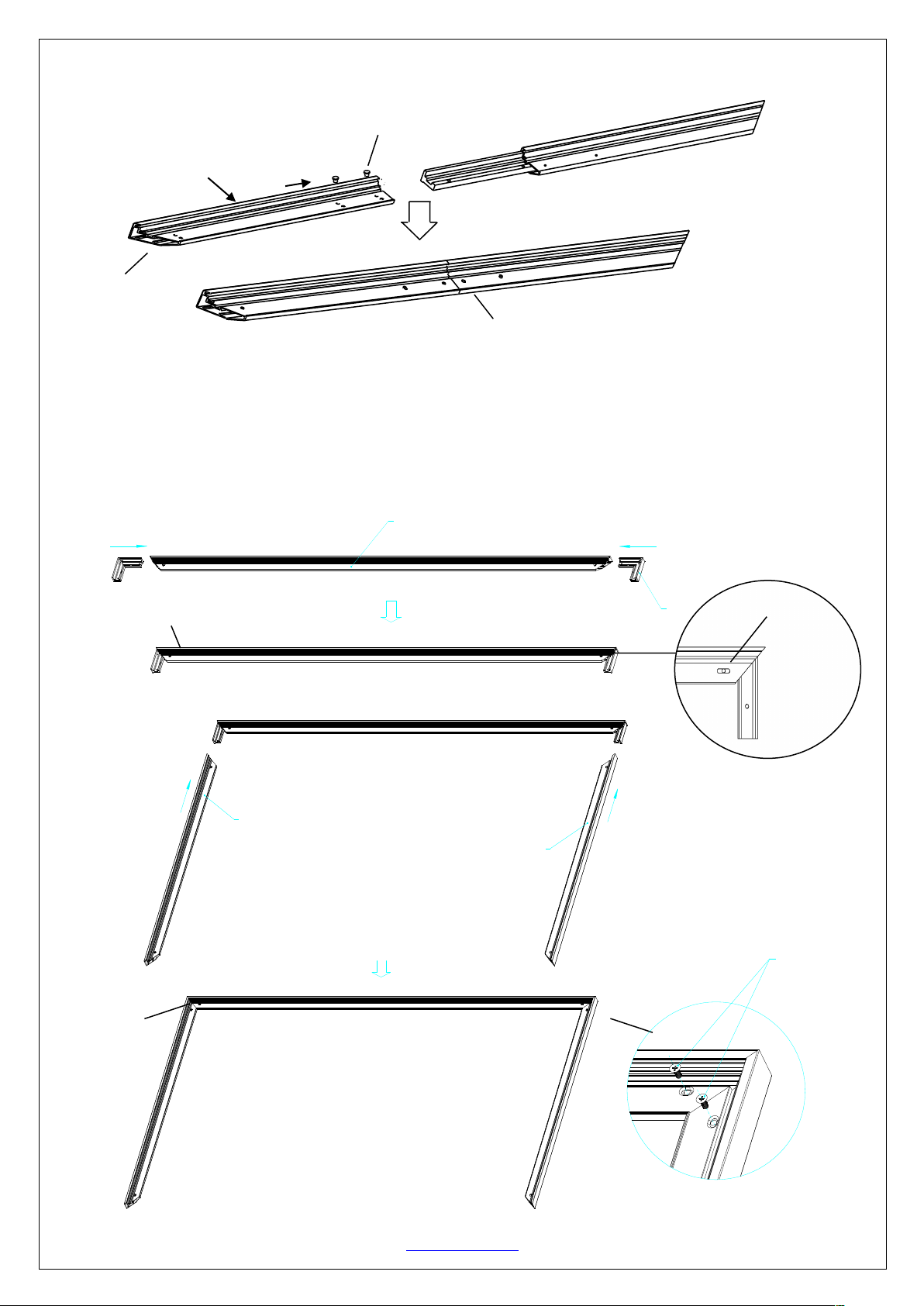
1. Insert the center joint connector to the ½ horizontal frame piece and fasten it with two M5x15 screws.
bevel connection
½ Long Frame
M5×15 Screw
Page 2
Rev.041114-JA www.elitescreens.com 2
Push
Push
Short frame
Short frame
2. Insert the other ½ horizontal frame piece to the center joint connector and fasten it with two M5x15 head
screws.&Repeat steps 1 and 2 for assembling the second horizontal frame.
Note: a. Two ½ size horizontal frames should be assembled for a screen.
b. Do not tighten the screws completely until all frame pieces have been assembled correctly.
3. Insert both elbow joint connectors into the long horizontal frame and fasten it with two M5x15 screws (seeFig.1).
Then insert the vertical short frames into the exposed elbow joint connectors and fasten them with screws (fig.1.2).
Bevel&connection&
M5x15 screws
½&Long&Frame&
Push&
Horizontal&Long&Frame
M5×15 screws
M5×15Screws
M5×15 screws
Screw
(Fig.1.1)
(Fig.1.2)
Push
Push
Joint
Long frame
( fig.1)
Page 3
Rev.041114-JA www.elitescreens.com 3
Push
Push
( fig.2)
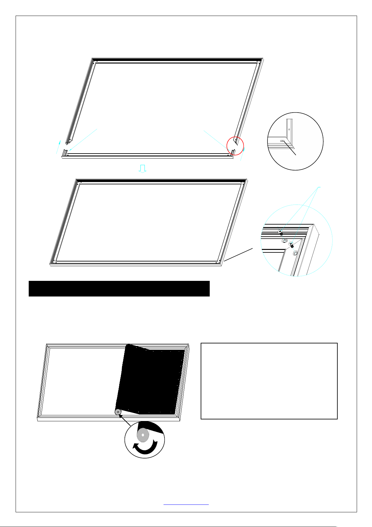
Insert the exposed ends of the joint connectors
into the short (vertical) frame and align the four
corners so that they meet at perfect right angles
4. Join&all&four&frame&parts&together&following &the &step s&sho w n &belo w .& (Fig.2)&
Note:&When&assembled,&please&push&simultaneously&the&two&ends&of&the&long&frames.&
&
Attaching the screen material to the frame
1. Make sure the screen material and frame are both lying face down on a clean, dry, and non-abrasive surface.
2. Carefully unroll the material inside the frame. (Fig.3)
Please note the material will be noticeably smaller than the frame, as the material must be stretched to create a
sufficient amount of tension for perfect material flatness.
3. Attach the fix plates.
(1)
Stretch the material to the corner and insert the screen material’s edge in the groove of the frame. While
one hand holds the material in place the other hand snaps in the push plate (Fig.4-Fig.5).
&
M5×15 screws
Screw
Notes:
• Make note of the label to help distinguish
the back and front side.
• Unroll the screen material face down
• Keep the screen material as close as
possible to the frame and do not allow it to
scratch against any part of the frame.
(Fig.3)
Page 4

Rev.041114-JA www.elitescreens.com 4
(2) Begin by securing the four corners in the following sequence A→B→C→D (Fig.6).
(3) Insert the fix the plates as shown on Fig. 5. Fix plate ① is about 10cm away from the frame’s corner.
Fix plate ② is about 5cm away. (Fig.7)
&
&
&
&
&
&
&
&
&
&
&
&
&
&
&
&
&
&
(4) Place a fix plate in the center of each side in the following order E→F→G→H. (Fig.9)
E G H
F
(Fig. 6)
(Fig. 7)
(Fig.9)
(Fig. 4)
Insert push plate in
Screen material edge
(Fig. 5)
Schematic cross section of the frame
Plate
Frame groove
A
B
C
D
Tip for attaching the last corner (D):
1. Position yourself left of location ①.
2. Pull the material to the corner of the frame with your hand while your left
hand snaps in the fix plate on location ① (the third red dot).
3. Then insert and snap in the fix plate on location ②.
4. Next, move and position yourself on location ③,then pull the edge to the
frame and fasten plates on locations ③ and ④.
5. Finally, fasten the last fix plate on location ⑤. (Fig.8)
①
②
③
⑤
④
Pull
(Fig. 8)
Page 5

Rev.041114-JA www.elitescreens.com 5
(5) Next, fasten a fix plate on the center of each frame side in the following order
I→J→K→L→M→N→O→P as shown in Fig.10.
(6) Fasten the remainder of the fix plates in the empty locations in the red markings to complete attaching the screen
material. (Fig.11)
Black backing for AcousticPro models
This procedure only applies to AcousticPro models. Disregard this section if your Fixed Frame does not include an
acoustically transparent screen material. The purpose of the black backing material is to block out any light
penetration that may reflect off of anything mounted behind the screen, which can cause distortion to the projected
image.
&
&
&
&
Interval markings reveal the best points for inserting the fix plates
(Fig. 12). The prongs on the fix plates insert to the lip on the back
of the frame creating a friction hold that will firmly keep the
material and black backing in place (Fig. 13-14).After the material
has been installed, the backing will lie over the back of the white
(Acoustic) material and then be held in place by the Velcro on the
fix plates (Fig 15).
(Fig. 12)
(Fig. 14)
(Fig. 13)
(Fig. 15)
(Fig.11)
The&black&backing&is&held&in&place&by&the&Velcro&that&is&on&the&fix&plates.&
Black backing
Fix plates secure the Acoustic material and
the black backing behind it.
I
J K L
M
N
O
P
(Fig.10)
Page 6

Rev.041114-JA www.elitescreens.com 6
Center Support Bard
1. Insert the support joiner into each end of the center support bar.
support joiner
Center support bar
2. Insert the Center Support Bar into the upper top groove on the back of the frame (not the one where the fix
plate inserts) with the bottom end near the approximate center point of the frame and rotate it in at an angle so that
both ends of the bar are in alignment with the groove (see Fig. 16 and Fig. 17 below for details).
Diagonal models 135” and below use 1 x Center Support Bar
Diagonal models above 135” require 2x Center Support Bars
3. Slide the top end of the bar into the top center point of the frame to complete the center support bar installation.
This will provide added stability to your frame and added tension to the material.
Screen material edge
Center&Support&Bar&
(Fig.&16)&
Fixed plate groove
(do not insert here)
Remove
push
Center&Support&Bar&
(Fig.&17)&
Page 7

Rev.041114-JA www.elitescreens.com 7
Installation&
1. Locate&your&desired&installation&location&w ith& a & stud&finder&(recommended)&and&mark&the&drillNhole&area&of&
where&the&screen&is&to&be&installed.&
2. Drill&a&hole&with&the&proper&bit&size&according&to&the&wood&screws&included.& &
3. Line& u p& the& wall& bra cke ts& with& the& drilled&holes& on&the& installation&location&and& screw&them& in&using& a&
Phillips&screwdriver.&
Note:&Use& 2& top&wall&brackets&on& diagonal&sizes&below& 135”,&and& use&3& top&wall&brackets&on&diagonal&
sizes&135”&and&above.&
4. Position&the& fixed& frame&screen& onto& the&top& wall& brackets&as& shown& in&(Fig.& 18)& and& pu sh& down&at& the&
center&of&the&bottom&frame&to&secure&the&installation.&
5. The&design&of& the&wall&brackets&allows&the&fra m e&to& slid e&over&them&through&its&sides.& This&is&an&important&
feature&of&the&installation&design&as&it&allows&your&screen&to&be&properly¢ered.&
6. Using& both& hands&finish&the& installation&by& pushing& the& lower&portion&of& the& fixed&frame&screen&into& the&
lower&bracket&as&shown&in&Fig&19.&
&
&
CAUTION
Please follow these instructions carefully to ensure proper maintenance and safety of your Fixed Frame Screen
1. When hanging the screen up, please make sure that no other objects such as power switches, outlets, furniture,
ladders, windows, etc. occupy the space designated for your Fixed-Frame screen.
2. Regardless if the screen is hung on or installed into the wall, make sure that the proper mounting anchors are used
and that the weight is supported appropriately by a strong and structurally sound surface just as any large and heavy
picture frame should.
(Please consult a home improvement specialist for the best advice on installation)
3. Frame parts are made of high quality velour-surfaced aluminum and should be handled with care.
4. When not in use, cover over the screen with a furniture sheet to protect it from dirt, grime, paint or any other
impurities.
5. When cleaning, use a damp soft cloth with warm water to remove any marks on the frame or screen surface.
6. Never attempt to use any solutions, chemicals or abrasive cleaners on the screen surface.&
7.&In&order&to& avoid& damaging&the&screen,&avoid& touching&it&directly&with&your&fingers,&tools&or&any&other&sharp& or&
abrasive&objects.& &
8.&Spare&Parts&should&be&placed&out&of&reach&of&small&children&in&accord a n ce &with&household&safety&g u id elin e s. &
For&a&local&Elite&Screens&contact&or& Technical& Support,& please& visi t&
www.elitescreens.c om &
(Fig. 18)
(Fig.19)
 Loading...