

Elite Screens CineTension 106H, CineTension 84H, CineTension 120H, CineTension 135H, CineTension 150H User Manual
...Page 1

Electric Scree n
CineTension2 Series
Ver.1.6
Users Guide
1
www.elit es cre en s. com/ eliteinfo@elitescreens.com
Page 2
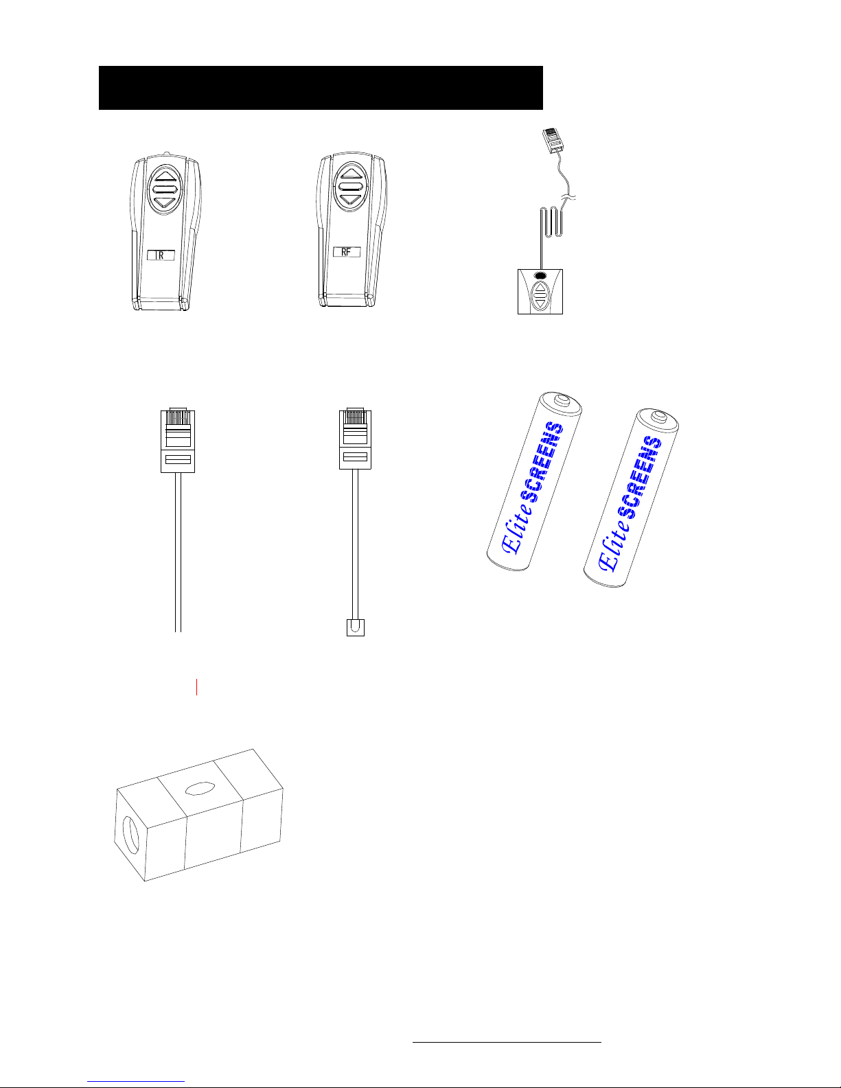
Accessories for Cine Tension 2
③
b
b
① IR ② RF
Red 1 2V (+)
④5/12V trig ger cable
Green 0V (-)
⑤
Please always point to the eye
receiver when using the IR remote
IR”eye” receiver
Wallbox
⑥
Batter ies
⑦ Bu
2
le level
www.elit es cre en s. com/ eliteinfo@elitescreens.com
Page 3

Important Safety and
W
t
b
t
p
ply
t
b
arningPrecaution s
1. Be sure to read this manual beforeuseand followtheprocedures specified:
Pl e a s e re t a i n th i s m an u a l f or future re ference.
To av oid any damage, do not use any accessories not r ecommended by the
manufacturer. Handle the device carefully during transportation to avoid impact.
Do not put the device on uneven or inclined surfaces.
Do not put heavy objects on the power cord; affix the power cord properly to avoid
someone tripping over it.
Never over load the power cor d to prev e n t electrical shock or fire.
G uard the device from any liq uid or foreign object to av oi d electr ical shock or f ire due to
loose contact or shor
2. If any accessories need to
circu it.
e replaced, be careful to avoid a shortcircuit.
3. There are no user serviceable parts in the device. Nobody except authorized technicians can
open this device. To prevent the risk of electrical shock or fire, protect this device against
moisture and rain.
Make sure tha
T he rating label on the product indicates the rated voltage.
Do not handle the power plug when your hands are wet or your feet are in contact with water.
th e po w e r s o u r c e t h i s d e v i ce i s c o n n e c t e d to has a continuous power flow.
4. Do not use this device under thefollowingcircumstances:
Disc o nnect th e power cord un der the conditio n of heavy win d, rain, thunder or
lightni ng.
Avoid direct sunshine , rain show er or moisture.
Keep away from fire sources and high temperature to prevent this device from overheating.
Cut off the power su
firs
efore transportation or maintenance.
Page 4

W
NOT
E
p
p
plying p
t
p
arning
Indivi dual modifica tions to this product are prohibited and will void the warranty. Please contac t
our Service Department for any questions.
This equipmen
ursuant to Part 15 of the FCC Rules.
These limits are designed to provide reasonable protection against harmful interference in a
residential installation. This equipment generates uses and can radiate radio frequency energy and, if
not installed and used in accordance with the instructions, may cause harmful interference to radio
communications.
However, there is no guarantee that interference will not occur in a particular installation. If this equipment
does cause harmful interference to radio or television reception, which can be determined by turning the
equipment off and on, the user is encouraged to try to correct the interference by one or more of the following
measures:
To ensure safe and reliable operation, direct connection to a properly grounded power source is advised.
The
Reorient or relocate the receiving antenna
Increase the separation between the equipment and receiver.
Connect the equipment into an outlet using a circuit different from where the receiver is connected
Consult the dealer or an experienced radio/TV technician f or help
:
ower outlet su
has been tested and found tocomply withthe limits for a Class B digital device,
ower to the unitshouldbe close to the unit a nd eas ily accessible
.
4
www.elit es cre en s. com/ eliteinfo@elitescreens.com
Page 5

①
b
b
②
1. 5/12V Trigger: The built-in 5/12V trigger
input for your new CineTension2 allows your screen
3-prong power cab le
to synchronize its drop and rise with the projector's power
cycle. The screen drops when the projector powers up and
retracts when the projector powers down. The 5/12 volt
adaptor connects to your projectors trigger output via a
separate cable that may or may not be provided by th e
projector manufacture. The trigger feature will not work
without an output cable from the projector, but it can be
tested using a 9-volt battery by simply connecting the Red
(+) and Green (-) cable to the 9-volt battery.
RJ-45 input connection for
5/12 volt trigger inside
of
case
Red: DC 12 +
Green: 0 V -
2. Wall Box and IR (Infrared) Eye Receiver: The 3-way Wall Box switch enables the consumer to
manually operate the screen's drop/rise capabilities. The IR “eye” protrudes from the bottom of the casing to present a low
profile line-of-sight control option for your IR remote. It is a low-vis ibility alternative to using the wall box kit and its
ability to protrude from the bottom of the screen allows line-of-sight control even in a recessed ceiling installation.
3-way Wall box switch
3.
Bubble Level: Included with the installation package is a small bubble level that can be useful in
determining if the screen is perfectly level when installing.
NOTE :
Please use the Down sign side as the bottom.
The Bubble should be in the middle position to determine that it is level.
5
www.elit es cre en s. com/ eliteinfo@elitescreens.com
Sensor
Sensor
Bu
le
Page 6

P
lease read this guide prior to installation.
–
● Make sure the current rating is equal to that of the appliance rating when an extension cord is used.
● Do not use any accessories not provided by the manufacturer with this screen. We will not be responsible for
any risks of fire, electric shock, or injuries resulting from the misuse of this product with accessories not
designed for use with this product.
● Make sure the screen is mounted in a horizontal level position. We suggest consulting with a professional if
you are unsure on how to perform a proper installation.
INSTALLATION
The CineTension 2 series screen is designed for installation on either a wall or ceiling. All hardware is included to
allow either installation method however we do strongly recommend a professional installation for safety purposes.
The extruded hanging brackets are designed to slide anywhere on the back of the screen to accommodate a
wall or ceiling installation and provide an easy alignment with wood studs and trusses.
Please follow the steps below for recommended installation instructions.
Mounting Hardware Kit – Please make sure all of the following items have been supplied before proceeding
installation.
Parts identification:
Qty 2 – Wood Screws
Qty 2 – Drywall Anchors
1. Begin by sliding the Bolts (B) thru the left an d right slide channel located on the top back of the CineTension 2
screen’s casing as shown on picture.
A
B
Qty 2 - Bolts
C
Qty 2 – Masonry screws
Qty 2
Masonry anchors
D
Qty 2 –Extruded
Hanging Brackets
Page 7

2. Slide the Extruded Hanging Brackets (D) thru the rail located below the slide channel until it meets with the top part
A
of the bolts (B) and then slightly tighten the lug-nuts located on the top and bottom of the bolt with a wrench to secure
the extruded hanging brackets.
3. Mark the location of where the screen is to be installed and drill your hole. Insert the proper screw into the drilled
hole and finish tightening the bolts to the bracket.
Masonry Anchors and Bolts (C) are used on concrete/masonry wall/ceilings.
Plastic drywall anchors (A) are included for drywall mounting.
Wood screws (A) are to be used for wooden wall/ceiling studs on screen sizes less than or equal to 120” inches
5. Examples of an installed CineTension 2 on a wall, ceiling and enclosed.
(diagonal).
Masonry anchors (C) should be used for wall/ceiling installations of screen sizes greater than
120 inches (diagonal). We strongly advise to consult with a professional for such ins tall ation.
Top hole for ceiling installation
B
Back hole for wall installation
C
D
Flush mount
to wall
7
www.elit es cre en s. com/ eliteinfo@elitescreens.com
Flush mount
ceiling
to
Enclosed
installation
*Allow 2” of spacing
between the front and
back of the screen casing.
Page 8

pp
The IR receiver will be connected from the screen
IR “eye” sensor
11.65 mm. in width
Although the IR remote requires a direct line of sight with the IR sensor to
function, the screen’s case can be hidden from sight and operated using the
RF remote. When depressing the directional buttons you should hear a faint
click signifying that the mechanism is working properly.
Power cord
rox. 6 ft. length.
A
80mm in width
IR RF
UP
Stop
Down
This is the IR (Infra-Red) remote with a
range of 15 Ft. Battery size AAA
** Please remember to always point to the wall switch receiver when using the IR remote. The IR remote can also work
with a Universal Learning Remote Control usually by programming the Screens IR codes into your Universal Learning
Remote.
This is the RF (Radio Frequency) remote
with a range of 30 Ft. Battery size AAA
8
www.elit es cre en s. com/ eliteinfo@elitescreens.com
Page 9

FO
p
R
REFEREN CE ONLY:
(Attention: This adjustment is not required. The screens tension has been set to achieve its
best performance. Always contact an Elite Screen Technician for assistance to avoid
damaging the screen and voiding your warranty.)
Pulling the knob and turning it Clockwise it will create more tension to the screen. By pulling the
knob Counter-clockwise it will start to release tension.
If the electric screen does not move, please check the following:
1. Check the power supply first. The screen will understandably not move without power.
2. Make sure the power cord is firmly plugged to the power outlet.
3. Make sure that all cable connections are secure.
4. If the screen works well with the line switch but not with the remote control, please make sure the
remote controls have fresh batteries or replace them with new ones. Change the battery every 6
Months to ensure proper operation of the remotes.
5. For all other
Or call 1-877-511-1211 Ext.202/234.
roblems, please contact Elite Screens at Techsupport@elitescreens.com
9
www.elitescreens.com/ eliteinfo@elitescreens.com
Page 10

N
p
d
h
1. Q: Why does my screen no longer function?
A: There are a few
ossible things you could check:
A.) Make sure your wall plug has power and that the screen is properly plugged in.
B.) Please check the fuse to y our screen. (Call Tech support for location of fuse)
C.) If screen works well with the line switch but not with the remote control, make sure the remote control has goo
batteries in it.
D.) Our electric screens with a tubular motor installed are equipped wit
include all Home (2, 3), Tension (1, 2, 3) series, and VMAX screens with a diagonal size above 180". This
feature will automatically shut off screen in the event the motor becomes too hot, preventing overheating of
the motor. To correct this, let screen alone for 10-15 minutes and try again.
a Thermal relay. This would
2. Q: How is the screen material cleaned?
A: The screen material can be cleaned with mild soap and water.
3. Q: What type of batteries do the remote controls require?
A: The IR and RF remote controls use AAA alkaline batteries
4. Q: Can you manually pull down the screen?
A: No, manually pulling down the screen will damage the electronic motor rolling system.
5. Q: How could I setup my Screens IR receiver to work with my learning remote control system? Do you have any IR
codes I can use to achieve this?
A: Our IR remote controls have been evaluated and entered in to the databases of some Universal remote control
manufacturers. Please contact the manufacturer of your remote to inquire about your remotes ability to function with
ours. If they have not evaluated our remote control then the following list of Binary codes will be used for most remote
setups.
For Spectrum, VMAX2 (Plus), Home2(3) and Tension2(3) Series
Up: 1111 0000 0001
Stop: 1111 0000 0010
Down: 1111 0000 0100
6. Q: What is the gain on the matte white screen material?
A: The matte white material has a gain of 1.1. For detailed specs, info please check our web-site for more detail
ote: For more Update FAQ, please visit www.elitescreens.com
10
www.elitescreens.com/ eliteinfo@elitescreens.com
Page 11

t
p
Two (2) year warranty parts and labor from purchase date as follows (except for refurbished units
as specified below):
Refurbished units carry a 90-day parts and labor warranty.
Demo units or open box items are AS IS items and do not carry a warranty.
Each party will be responsible for one way shipping during the warranty period.
DOA (Defective On Arrival): Must be reported within 7 business days of receipt. An RMA
(Return Merchandise Authorization) number must be issued in order to process a replacement.
Elite Screens will replace the DOA (Defective On Arrival) unit with a brand new replacement
*(see exceptions below) after the DOA unit is received and/or confirmed defective. Once the
roduct is received, Elite Screens will send out a new* unit to the customer by ground service
(based on stock availability). Should a problem be reported after the 7-day grace period, the item
must be shipped to us for warranty repair.
Missing Parts must be reported within the 7-day (DOA) grace period. If reported after 7 days,
customer will be only responsible for shipping and handling fees. If reported after 30 days of
receipt, customer is responsible for cost of the parts and shipping & handling fees.
*A new or refurbished replacement will be sent out to the customer depending on the type of purchase (new or
refurbished) or based on stock availability.
Please do not return any unauthorized items to Elite Screens, as they will be refused.
The RMA number must be included on the outside label of your shipping box and shipping documents. Our
warehouse is not authorized to accept returns without an RMA number on the shipping label. RMA numbers are
valid for 45 days from the date of issue.
● All shipping damages must be reported within 7 business days upon receipt of the Produc
responsible for all incurred costs
● Inspect all shipments upon arrival. If damage or loss is apparent upon delivery do not accept the shipment until you
make a notation of the damage on all copies of the carrier's delivery receipt and have the driver sign all copies to
acknowledge the damage. Do not sign a clear receipt for damaged or missing items or there will be no basis for a
claim. Ask the carrier to make a detailed inspection of the damage. File a claim with the carrier. Cooperate and
follow up as necessary to secure final settlement
● Immediately advise Elite Screens of all damages or problems. Do not return merchandise to Elite Screens. File your
claim with the carrier enclosing copies of the bill of lading (signed by the driver) and inspection report as support. Keep
all packing materials and boxes with the damaged product. DO NOT throw any thing away. Although Elite Screens will
provide any assistance possible we can not be responsible for the actual filing of claims on the carrier or accept liability
for non-collectable freight claims
For Warranty and Service requests please fill out a RMA /Service Form at:
http://www.elitescreens.com/service_form.htm
Please Visit this link for full Warranty information:
http://www.elitescreens.com/service.htm
For Customer Service and Technical questions, please contact Elite Screens at:
Telephone:(877)-511-1211 Fax:(562)-483-8498
11
www.elitescreens.com/ eliteinfo@elitescreens.com
.
. After 7 days Customer is
Page 12

_____
___
_____
_
_ _ ____
___
_____
_
_ __
y
____
_____
___
_____
___
____
_____
___
_____
____ _
_ _____
_______
___
____
_ _ _____
___
_____
_
___
__
_ _ _
_____
___
_____
_______
_ _______
___ ___
____
_____
____
y
___
_____
_
_ ____
pp
___
___
___
___
__
_
y
___
___
___
___
y
@
Two ways to register your warra ntywith Elite Screens Inc.
A. Online (F aster and Easier) www.elitescreens.com/register.htm
B. Fill out & Fax to (562) 4 83-8498, Attn: Customer Service Dept.
*Your Name: _ _ _
Address: _
Cit
/State/Zip
*Email Address:
*Phone:
*Screen Model:
*Serial Number:
*Date of Purchase:
_
*Dealer / Reseller Purchased from (name of the reseller):
What is
A
How would
Comments:
If
ou have pictures of your screen you'd like to share with us, please email your pictures to:
For any technical inquiries, please email to
techsupport@elitescreens.com
our Projector Model:__
lication:
Home
Others
ou rate this screen?
Education
Excellent
Eliteinfo@elitescreens.com
Or call us at 877-511-1211 Sales and
or 877-511-1211 Customer Service Div
Corporation
Good
Marketing Div.
Ok
Government
Improvement needed
For any warranty claim inquires, please email to
elitescreens.com or 877-511-1211 Customer Service Div.
rma
12
www.elitescreens.com/ eliteinfo@elitescreens.com
Page 13

13
www.elitescreens.com/ eliteinfo@elitescreens.com
Page 14

B4
C1
B3
B2
B1
A2
A
C
B5
A
1
14
www.elitescreens.com/ eliteinfo@elitescreens.com
B
 Loading...