

Elite Screens AR100H2 User Manual

EDGE FREE
Series is a fixed frame projection
ign resembles a giant size flat
an installation option to further enhance the frame appearance and
for added visual appearance
For further assistance, watch our assembly and installationvideo at
assembly
please visit:
re included before installation
B.
Fixed Frame Projection Screen
uses Elite’s EDGE FREE
The Aeon includes a
sorb projector overshoot
vertical
. Wall brackets x
M6x12 screw x
L. Screwdriver x
4
Aeon Series
Applies to all available screen materials:
Product Description: The Aeon
technology. The EDGE FREE® des
backlighting kit is available
Assembly Video:
www.elitescreens.com/video/aeon-
For more information on the LED kit
Hardware and Parts List
Please make sure all parts listed below a
A. Elbow joint x 4 pcs
D. Center joints x 2 pcs
®
User’s Guide
CineGrey 3D®, CineGrey and CineWhite™
screen that
panel TV display.
ab
.
or scan the following QR Code:
http://www.elitescreens.com/led
.
Top/Bottom horizontal fame x 4 pcs C. Left/Right
E. Center Support bar x 1-2 pc F
®
velvet tape as
. An optional LED
frame x 2 pcs
2-3 pcs
G. M6 screw x 2-12 pcs
J. M5x50 screws/anchor x 6 pcs
M. Velvet tape
V051616-EA
H. M5x15 screw x 24 pcs I.
K. Rubber hammer x 1 pc
N. Corner Support Bar (180”-200”) x
www.elitescreens.com
2-12pcs
1 pc
pcs
1
ElbowJoint
(A)
ElbowJoint
(A)
Frame Assembly
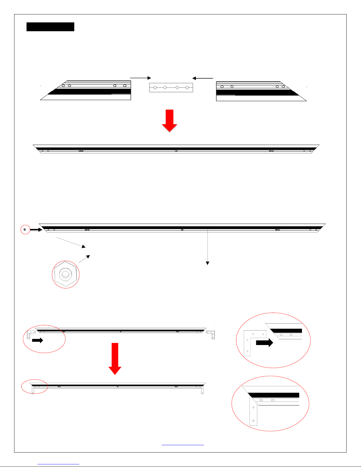
1. Insert the center joint (D) into one of the ½ horizontal frames (B) and fasten it with the two M5x15 screws (H).
2. Insert the other ½ horizontal frame piece to the center joint and fasten also using two M5x15 screws.
3. Repeat steps 1 and 2 for assembling the second horizontal frame.
Push Push
4. For models 150” and below, insert and slide in oneM6 screw(G) through the channel located on the backeach
horizontal frame section (top/bottom).
Note: For models 180” and above, insert and slide in four M6 screws (two on each frame) through the channel
located on the back of each horizontal frame section(top/bottom). Insert two M6 screws on each vertical frame
section(left/right).
M6 hex screws (G)
Top right Frame
Center Joints
Top left Frame
Horizontal frame
Horizontal long frame
5. Insert the elbow joint (A) into each end of the horizontal frames(B)as shown below.
Face up
Place one M6 hex screw (G) in the center for attaching the center support bar (E)
Horizontal long frame (B)
V051616-EA www.elitescreens.com 2
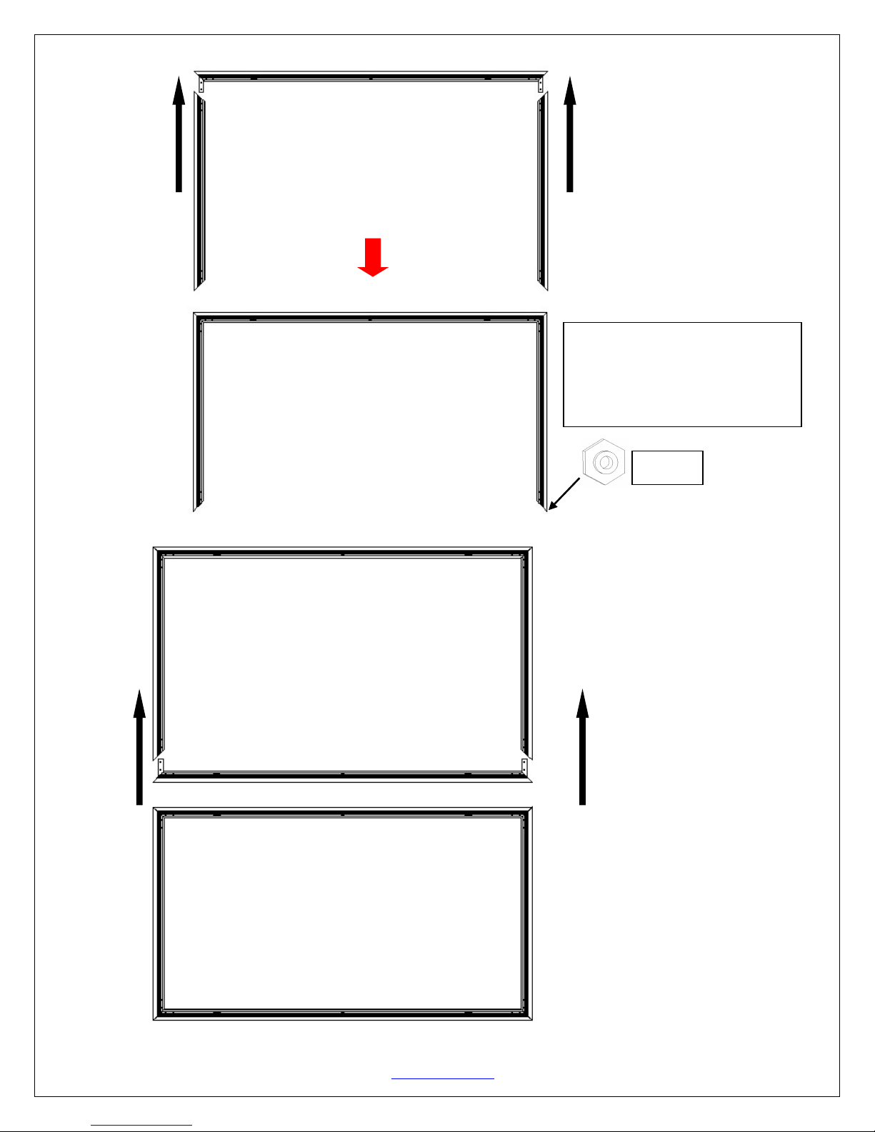
6. Insert the two vertical short frames (C) into the elbow joint (A).
7. Join the remaining horizontal long frame (B) with the frame built in the previous steps as shown below.
Vertical short frame (C)
Horizontal long frame (B)
push push
Vertical short frame (C)
Note: For models 180” and above,
ensure two M6 screws (G) are
inserted on each vertical frame
before proceeding to step 7.
Face up
push
push
Horizontal Long frame(B)
V051616-EA www.elitescreens.com 3
8. Make sure all four corners are properly in place to form a perfect square. Then fasten the four angles with the
M5x15 Screws (H).
Four corners join correctly to form a perfect
square. Use the included screwdriver (L) to
fasten the Mx15 screws (H) into each corner
by aligning the frame screw holes to the
holes in the elbow joint (A).
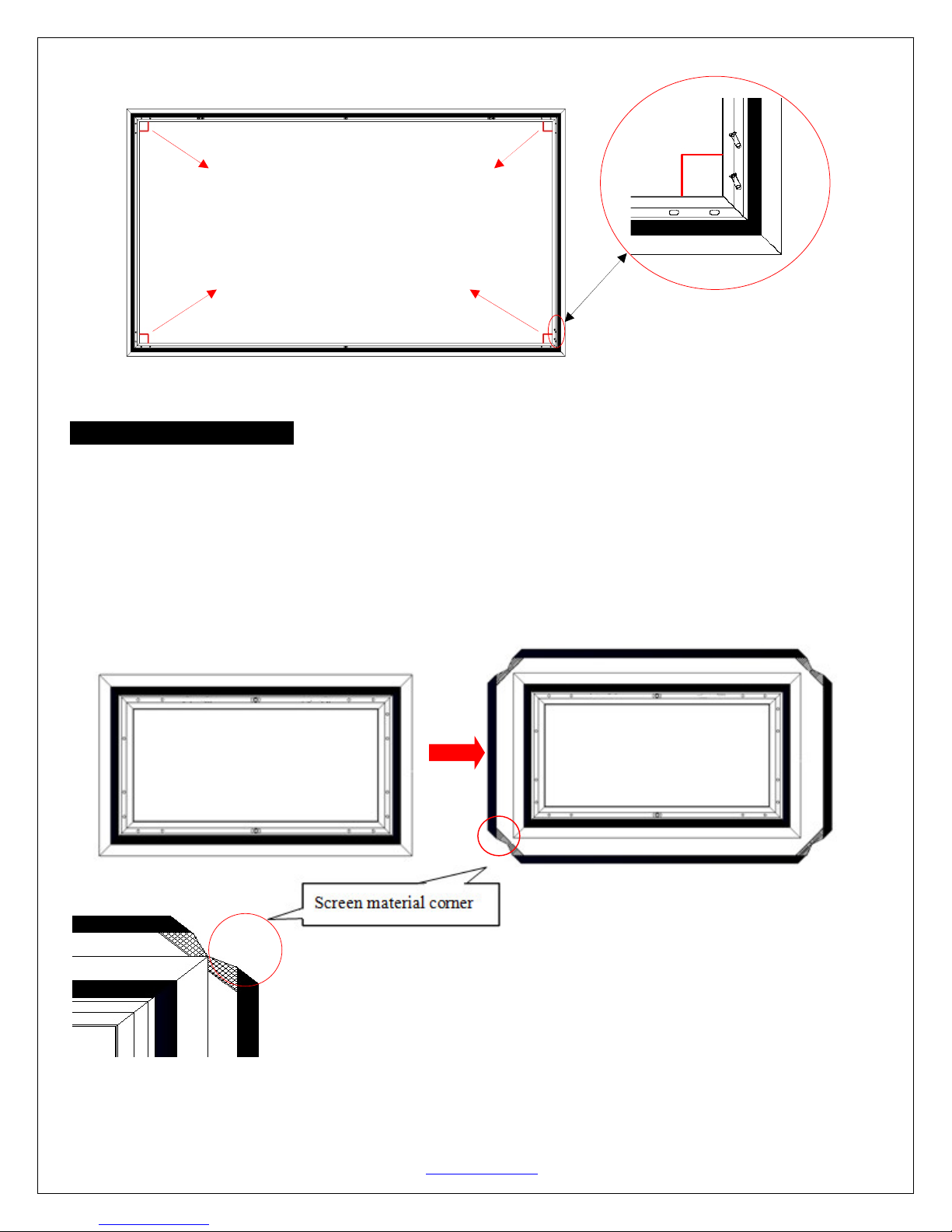
Screen Material Installation
1.Lay the screen material completely flat with the front facing down on a clean surface in a horizontal position. The
back side of the screen material should be placed upwards.
Note: The back side of the material has the velcro borders all around the edges.
2. Carefully and gently place the assembled frameon top the screen material as shown below. Make sure to not allow
the angle edge of the frame to come in direct contact with the screen material to avoid puncturing it.
Screen material back facing up
V051616-EA www.elitescreens.com 4
 Loading...