

Elite Screens Aeon CLR Series, Aeon AR90H-CLR, Aeon AR100H-CLR, Aeon AR120H-CLR User Manual
Page 1
1
2
3
4
5
6
7
8
9
10
3
11
12
7
13
14
15
12
1
3
2
8
6
11
10
9
3
15
13
14
12
18
17
16
19
Aeon CLR® Series (spring type) | User’s Guide -03252019MZ
Unit: mm (inch)
A B C
D
AR90H-CLR
2013
(79.3”)
1993
(78.5”)
1142
(45.0”)
1122
(44.2”)
AR100H-CLR
2234
(88.0”)
2214
(87.2”)
1265
(49.8”)
1245
(49.0”)
AR120H-CLR
2677
(105.4”)
2657
(104.6”)
1514
(59.6”)
1494
(58.8”)
Dust, dirt and scratches on the projection screen
surface will affect the quality and performance
of the projection image. Follow the instructions
below to properly maintain the screen.
1) The screen surface has a horizontal structure.
DO NOT wipe the screen up and down or in a
circular motion. Wipe from left to right only.
2) Clean the dust on the screen surface with a
soft brush or microfiber cloth. A rough towel or
cloth may damage the screen’s surface.
3) Gently wipe the screen with a moistened
microfiber cloth with mild soap diluted in
water.
Notes: The following precautions should
always be followed to avoid damaging the
material, which is not covered under
warranty.
• Don’t touch the screen material to avoid
leaving fingerprints. Use gloves when
handling the material.
• Don’t scratch the material, as it will leave
permanent markings on the screen’s surface.
• Don’t point to the screen material with a
fingertip or other sharp objects to prevent
damage to the material.
• Don’t use acetone, benzene, alcohol and any
other organic solvents to clean the screen
A
B
DC
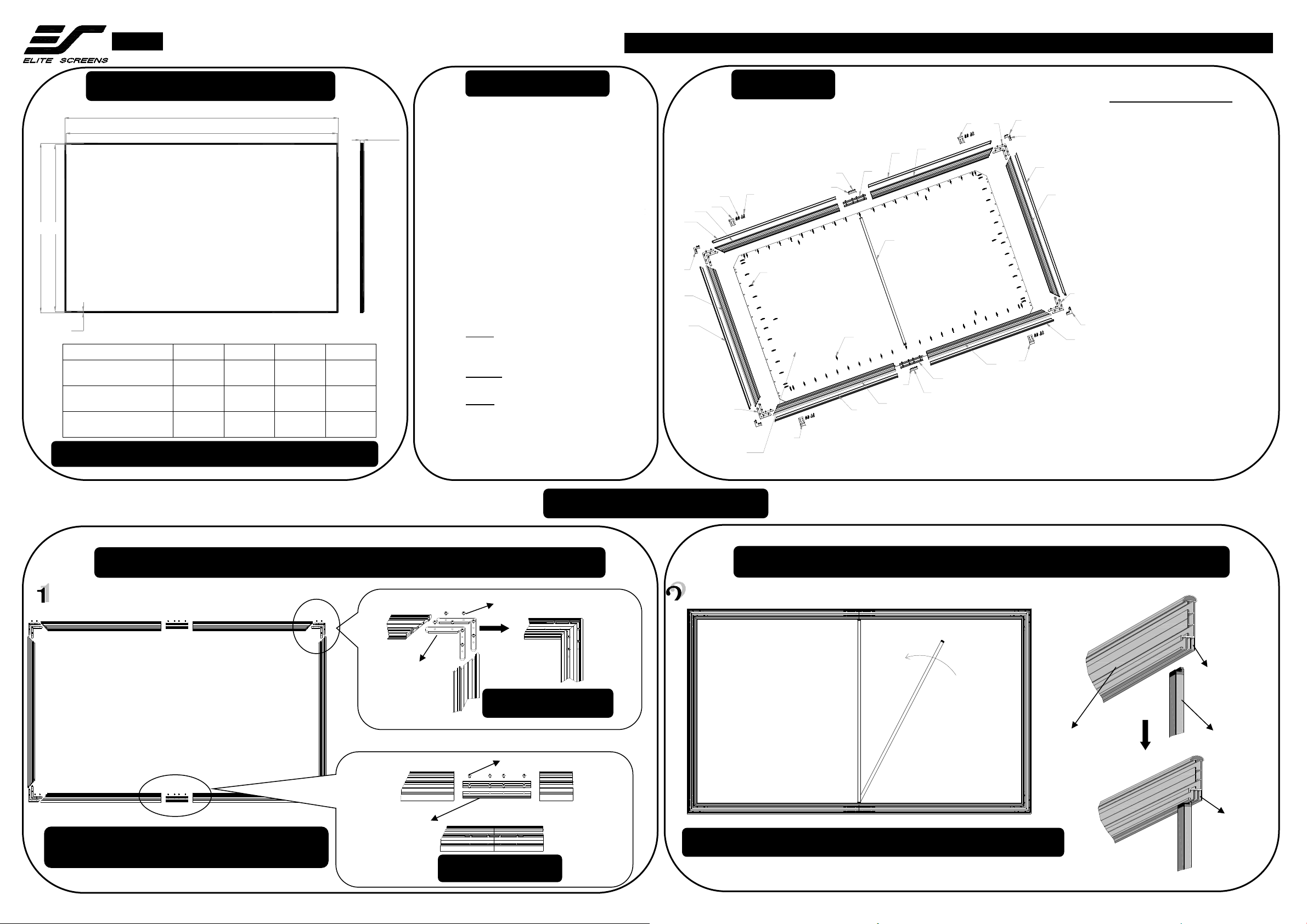
Dimensions Table
Screen Maintenance
Exploded view
Hardware and Parts List
(1) Edge Trim A x2
(2) Frame A x2
(3) Wall Bracket x4
(4) Anchor x8
(5) Wood crews x8
(6) Short Center joints x2
(7) M4x4 Screws x24
(8) Long Center joints x4
(9) Edge Trim B x2
(10) Frame B x2
(11) M5x6 Screws x48
(12) Elbow Joints b x4
(13) Edge Trim C x2
(14) Frame C x2
(15) Elbow Joints a x8
(16) Support Bar x1
(17) Springs a x74-84
(18) StarBright CLR® material x1
(19) Springs b x8
Screen Installation
Frame Assembly
Center support bar Installation
Insert the support bar’s
tip into the frame’s
groove in the middle,
then rotate it and insert
the other end on the
other side of frame.
(16) Support
Bar
See illustration on the right side on how to properly install the Support bar.
Frame
(back side)
Note:Make sure all holes are in alignment and the
frame pieces are flush (no gaps), then fasten the screws.
(8) Long Center
joints
(11) M5x6 Screws
Center Connection
Note: The listed measurements are for general reference only.
(15) Elbow Joint a
(11) M5x6 Screws
Corner Connection
(2) Frame A
(10) Frame B
(14) Frame C
(2) Frame A
(10) Frame B
(14) Frame C
Frame Width =
28.2 mm (1.1”)
Insert groove
Support Bar
properly inserted
into groove
Page 2
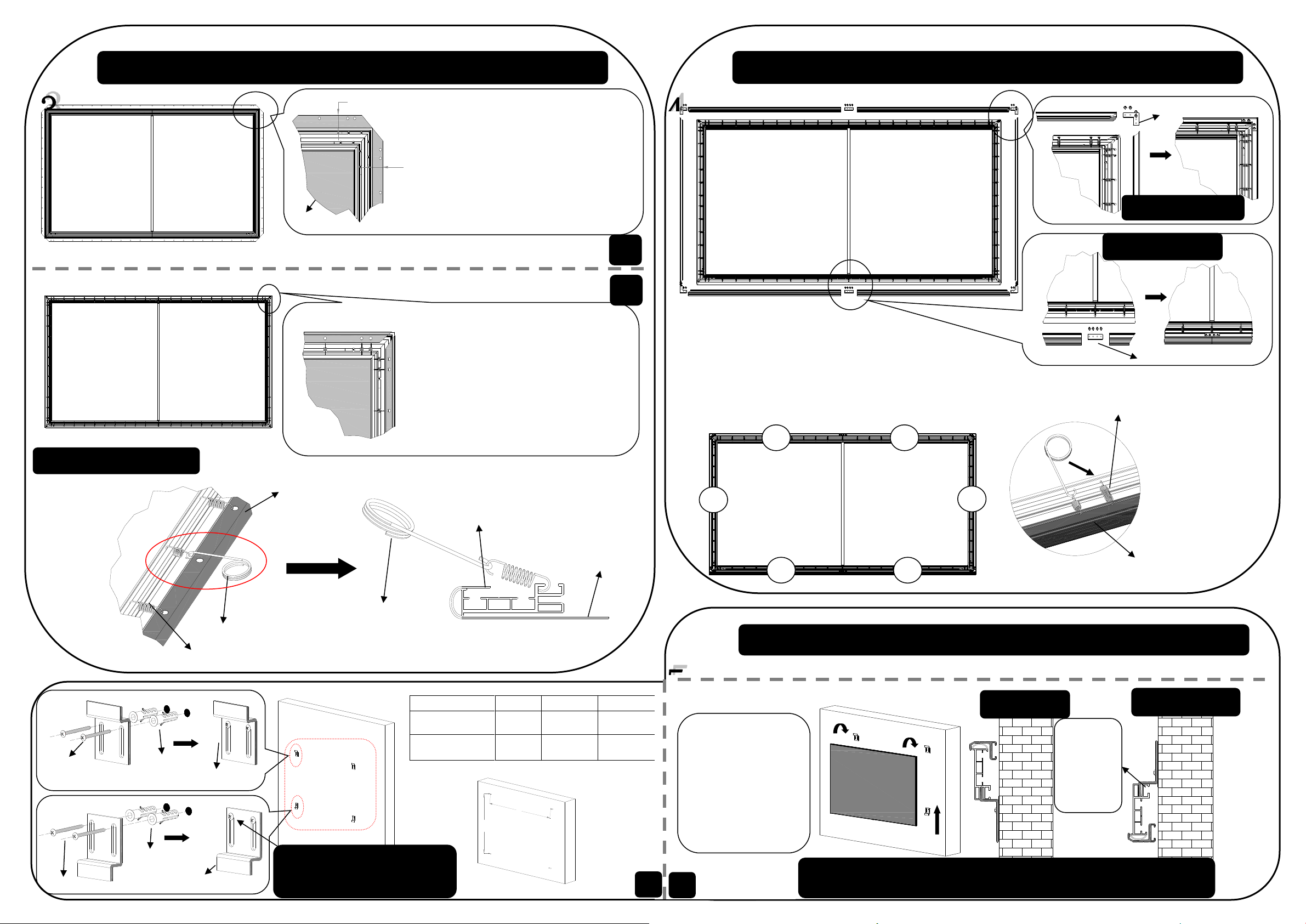
L
H
Unit:mm(inch)
90
100
120
L(Length of left
to right)
1500
(59.1”)
1500
(59.1”)
2000
(78.7”)
H(Length of top
to bottom)
960
(37.8”)
1083
(42.6”)
1332
(52.4”)
Wall Installation
Screen Material Installation
Edge Trim Installation
1. Put on the supplied pair of white gloves,
two people carefully unroll the material on
the supplied cloth (keep the front of the
material face down)
2.Carefully and gently place the assembled
frame on top of the screen material.
3. Adjust the distance between the edge of
the frame and the material (a1 = a2) to 35
mm/1.4”
Backside
Spring Attachment Method
Two people required
1. Begin by simultaneously attaching three
springs in the center of the side frames (A→B)
and repeat for top/bottom frames (C→D).
2. Then, simultaneously attach the springs from
the center to all corners.
3. Finally, attach the springs at the four corners
(E→F→G→H).
4. Inspect the assembled screen for flatness.
C D A B F E G
H
①
Corner Connection
Center Connection
(12) Elbow Joints b
(6) Short Center joints
Top Bracket
Bottom Bracket
Note: The
bottom
bracket
can be
adjust
from top
to bottom.
Tolerance:±3mm(.12”)
Spring hook
(18) Material
Note: Do not fasten up the screws
on the bottom bracket, so the
bracket can be easily adjusted.
1. Connect edge trims A&B to form the top/bottom
trims with the Short Center joints, and then insert
them on the top/bottom frames.
2. Connect the side edge trims C with the
top/bottom edge trim with elbow joints b.
3. Adjust the trim so that the top and bottom trim
pieces are touching and show no gaps on the
corners. Then fasten them with the M4 x4 screws.
②
(1) Two people hold
the screen. First align
and place it on the
bottom bracket.
(2) Then pull up the
screen on the top
bracket and adjust the
screen left to right as
needed.
Note: Make sure the direction of the CLR material is correct before you hang the
screen to the wall. The material is labeled top or bottom.
4.Attach a spring b
on the middle of
each edge trim (1-6)
to the frame as show
on the left
illustration.
Edge Trim
(19) Spring b
(17) Spring a
(1)
(2)
a1
a2
a1=a2
(18) Material
Spring hook
Hole on the material
①
②
Hook springs on frame
then use spring hook to
attach to material
(5) Wood Screws
(4) Anchor
(3) Top Wall Bracket
(5) Wood Screws
(4) Anchor
(3) Bottom Wall Bracket
 Loading...