

Page 1
Yard Master Plus Series
Indoor/Outdoor Portable Projection Screen
User’s Guide
Thank you for choosing the Yard Master Plus portable projecti on screen! Please read through this user
guide before utilizing the screen. Correct usage and maintenance will ensure a long product life
Care & Use Instructions
◆ Elite highly recommends two people to assemble the Yard Master Plus screen.
◆Dust, dirt and scratches on the projection surface will affect the picture quality, please take note o f the
points below to prevent that from occurring:
1. Do not touch the projection surface with your hands
2. Do not write or draw on the projection surface
3. Do not use fingers or sharp objects to point on the projection surface; this will damage the screen
material.
4. Use a soft-damp cloth to clean the projection surface; do not use chemical cleaning agents or
alcohol.
5. Use clean water when dampening the cleaning cloth and do not rub against the material to clean it.
◆After using the screen, disassemble it and store it in the carrying bag provided.
◆To avoid damage and injury, the screen should only be operated by adults.
Product Description
Design: The aluminum frame is designed to be light weight and easily operated making it easy to ca rry,
assemble and disassemble.
Screen Fabric: The screen fabric is attached to the rectangular frame and held in place by several press
stubs, which ensure an evenly stretched and flat surface. The CineWhite® (front projection) screen
material is durable and can be folded many times without causing damage or distortion to the surfac e.
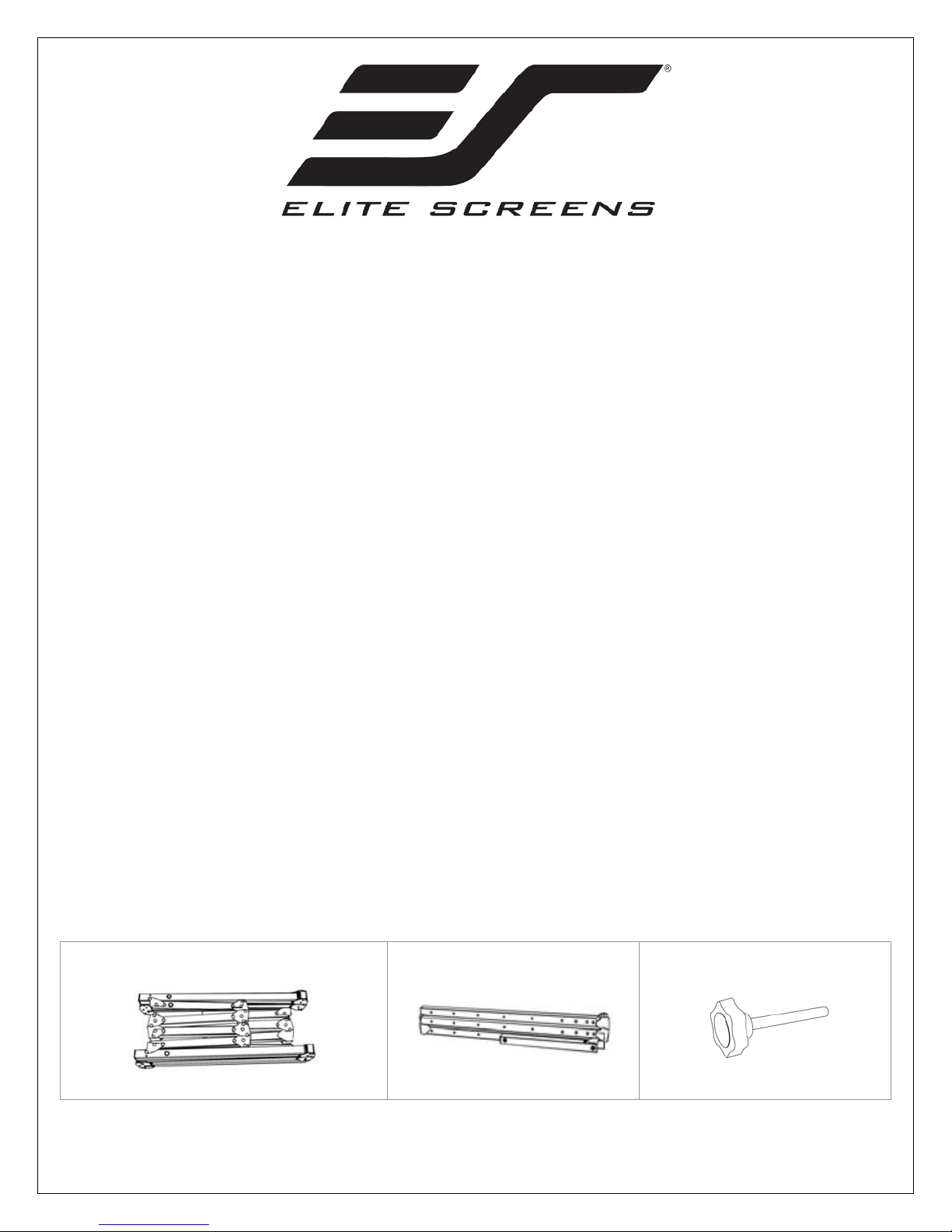
Parts Diagram
A. Folding fra me x1
Rev. 041818BR 1 www.elitescreens.com
B. Left and right folding legs x2
C. Knob Screw (Refer to Chart)
Page 2
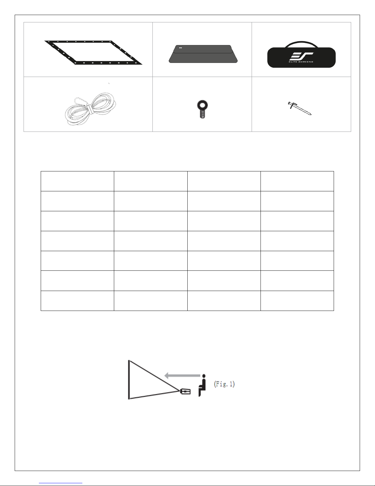
D. Projection screen material x1
E. Screen material bag x1
F. Carrying Bag x1
G. Rope x2
H. Eyebolt x2
I. Stake x4
Note: The parts list above is subject to change without notice.
Models Knob Screw Support Leg Max Height
100” (16:9) 8 pcs N/A 95.5 inches
120” (16:9) 8 pcs N/A 112.2 inches
135” (16:9) 10 pcs Included 113 inches
145” (16:9) 10 pcs Included 133.5 inches
180” (16:9) 10 pcs Included 159.8 inches
200” (16:9) 14 pcs Included 149.6 inches
Correct usage of the projection screen will ensure better viewing results.
For front projection, assemble and view the screen as indicated in Fig.1.
Rev. 041818BR 2 www.elitescreens.com
Page 3

Frame Assembly
1. Take the folding frame (A) out o f the carrying bag (F) and place it on a flat surface. Fully unfold the
longer sections first, as shown below
.
2. Next, unfold the frame until the latch on the hinge “clicks” into place. Repeat the procedure for the
shorter sections, as shown below.
Note: When unfolding the frame and legs, be sure the latches on the hinges "click " into place. Please also
make sure all 4 corners of the frame are at a 90° angle and the hinged support bar is straight and not bent.
Screen Material Attachment
1. Take the screen material (D) out of the screen material bag (E) and align the corners of the screen
material with the inside corners of the frame.
Rev. 041818BR 3 www.elitescreens.com
Page 4

Warning: The additional support sections, located at the middle section of the legs, may unfold on its own. Please
be sure to use caution while removing/placing the legs from/to the bag
Fig.1
Warning: When attaching the legs, make sure to screw the top of the leg to the last hole of the frame to reach max
when assembled.
1 3 2 4 5 6 8
7
2. Once the screen material is fully extended, secure the material by snapping the buttons onto the frame
studs. Fasten the buttons in the following order as shown on Fig.1.
Note: Snap the buttons on each corner first, then work your way out to the center on each side.
Leg Attachment for 100 ”/ 12 0 ” Mode l s
1. Carefully take the left and right folding legs (B) out of the carrying bag (F) and place it on a flat
surface. Unfold the left and right legs leaving the front foot folded as shown below. Make sure the hinges
click into place.
2. Once the legs are unfolded, lay the frame on the floor and position the legs over both sides of
the frame. Use the knob screws (C) to attach the frame to the legs.
height. Attaching the legs lower to the frame and leaving an extra space on top may cause the screen to tip over
Rev. 041818BR 4 www.elitescreens.com
Page 5

Warning: When attaching the legs, make sure to screw the top of the leg to the last hole of the frame to reach max
when assembled.
3. After making sure the legs are secure to the frame, using two people, lift the screen up in a
vertical position. While the screen is in a vertical position, fold the front feet of the legs out.
4. The assembly is now complete and the projection screen will be stable on a flat surface.
Leg Attachment for 135” – 200” Mod els
1. Starting from step 2 on the previous procedure, lay the frame on the floor and position the legs
over both sides of the frame. Use the knob screws (C) to attach the frame to the legs.
height. Attaching the legs lower to the frame and leaving an extra space on top may cause the screen to tip over
2. Next, carefully unfold the extra support leg behind the leg and attach it securely using a knob screw (C).
Then repeat steps 3 and 4 on the previous procedure.
Rev. 041818BR 5 www.elitescreens.com
Page 6

Screen Disassembly
1. After using the screen, disassemble and store it in the carrying bag (F). To disassemble the screen,
follow the assembly procedure in reverse order.
2. Store the screen in the provided carrying bag (F). Be sure to place folding frame, legs, and smaller
parts into the carrying bag first and place the material on top to keep material from creasing or tearing .
For more information, technical support or your local Elite Screens contact, please
visit
www.elitescreens.com
Rev. 041818BR 6 www.elitescreens.com
 Loading...