


6/29/17-JA www.eliteproav.com 1
!
Aeon%ALR%Series%%
EDGE FREE® Ambient Light Rejecting Fixed Frame Screen!
USER’S GUIDE
Product Description:
The Aeon ALR Series is a fixed frame projection screen with an EDGE FREE® design. The EDGE FREE®
design resembles a giant size flat panel TV display. It includes a micro-thin black bezel trim to further enhance
the frame appearance and absorb minor projector overshoot. An LED kit is also included for mood lighting.
The screen material included is our ISF certified CineGrey 5D®, which is a reference quality front projection
material precisely formulated for environments with minimal control over room lighting. It was designed to
enhance picture brightness, provide accurate color fidelity, and improve contrast. The CineGrey 5D is best for
family rooms, educational facilities, conference rooms or any applications in which incident light is a factor.
In order for the CineGrey 5D to maintain its projection qualities and optimum performance, please refer to the
list below for proper maintenance and cleaning.
• Use a dry microfiber cloth to remove dust from the screen’s surface.
• When cleaning, use a damp microfiber cloth with warm water to remove any marks.
• Never rub or apply pressure when cleaning the surface.
• Never attempt to use any solutions, chemicals or abrasive cleaners on the screen surface.
• In order to avoid damaging the screen, avoid touching it directly with your fingers, pens/pencils or
any other sharp or abrasive objects.
1.!Frame!and!Edge!Trim!Parts!List
Qty
item
2 pcs
Main Frame Parts
Qty
item
2 pcs
Edge Trim Parts
Part
A.
vertical frame
Part
D.
Part
B.
½ horizontal frame
Part
E.
Part
C.
½ horizontal frame
Part
F.

6/29/17-JA www.eliteproav.com 2
2.!Hardware!Parts!List!
a.!
b.!
c.!
d.!
e.!
f.!
g.!
!
h.!
i!
j.!
k.!
l.!
m.!
!
Item
Parts List
100H
110H
120H
135H
150H
180H
200H
a.
Center Joints (1)
4 4 4 4 4 4 4
b.
Elbow Joints (2)
8 8 8 8 8 8 8
c.
M4x6 Screws
60
60
60
60
60
60
60
d.
Spring Hook
2 2 2 2 2 2 2
e.
Spring
88
94
104
116
128
166
172
f.
Top wall brackets
2 2 2 2 2 2 2
g.
M5x50 Wall Screws
6 6 6 6 6 6 6
h.
Hollow Wall anchors
6 6 6 6 6 6 6
EEFDDAABBCC

6/29/17-JA www.eliteproav.com 3
Frame Assembly
Step 1: Place thesoft padded EPE sponge on clean area on the ground where the screen will be assembled.
Step 2: Position the pieces of the frame on the EPE sponge in the arrangement shown below
Step 3: Remove the tape on all frame ends before assembling the frame
Step 4: Insert the center joint (a) connectors into one-half of the horizontal frame (b/c) and secure with the
M4x6 screws (c).
Step 5: Insert the springs (e) into the grooves of the frame. The spring’s hooks should be facing the front side
of the frame. For the correct amount of springs to place into the frame, please refer to the table listed below.
i.
Bottom wall brackets
2 2 2 2 2 2 2
j.
Angle cover
4 4 4 4 4 4 4
k.
LED light strip clip
8 8 8 8 8 8 8
l.!
Center Support Bar
1 1 1 1 1 2 2
m.!
White gloves
2 2 2 2 2 2 2

6/29/17-JA www.eliteproav.com 4
Note: The springs are pre-installed into the grooves of the frame.
Step 6: Connect the elbow joints (b) to the top and bottom sections of the vertical frame. Once inserted, connect
the vertical sections of the horizontal frame sections. Make sure all holes are in alignment and the frame pieces
are flush (no gaps). They should form perfect right angles.
Step 7: Secure the elbow joints by fastening them with M4x6 screws (c), 4 at each corner.
Screen Material
Step 8: Put on the white gloves (m) and carefully unroll the screen material on a clean surface from the roller to
the other side as shown below. The back side of the screen material should be placed upwards.
Step 9: Carefully and gently place the assembled frame on top of the screen material. Make sure to not allow
the angle edge of the frame to come in direct contact with the screen material to avoid puncturing it.
Screen Size
EF
84H
EF
100H
EF
110H
EF
120H
EF
135H
EF
150H
EF
180H
EF
200H
EF
125C
EF
138C
EF
158C
Spring
Qty
A
23
28
30
33
37
41
50
55
37
40
46
B
13
16
17
19
21
23
28
31
16
17
20
Back side
Front

6/29/17-JA www.eliteproav.com 5
Step 10: With one end of the spring and secure inside the groove of the frame, use the spring hook (d) to attach
the spring to the hole located on the screen material’s outer edge in the following order.
Attach the four corners first (1). After those are secure, connect the vertical portions of the material, begin in the
center and move towards the corners (2). Lastly, connect the horizontal sections of the material by connecting
the center of the material and make your way towards the corners (3).
Note (after all springs have been attached):
Correct material installation –Corners of the screen material are properly wrapped around the corner edges of
the frame and material is evenly tensioned and flat, creating a nicely taut surface.
Incorrect material installation –The corners of the screen material are not properly wrapped along the edge of
the frame leaving the material with unbalanced tension and an uneven finish. To correct, detach springs from
material at the corner(s) where material does not lie flat along the edge of the frame, reposition the material so
that it lies flat and wraps along the edge of the frame, and reattach springs to the material.
Back Side
1
1
1
2 2 3

6/29/17-JA www.eliteproav.com 6
Center Support Bar
Step 11: Insert the Center Support Bar (i) into the upper top groove on the back of the frame with the bottom
end near the approximate center point of the frame and rotate it in at an angle so that both ends of the bar are in
alignment with the groove.
Diagonal Models 150” and below use 1 x Center Support Bar
Diagonal Models above 150” require 2 x Center Support Bars
Attention: Do not proceed with the Edge Trim installation until making sure there
are no ripples in the material.
Edge Trim Installation
Step 12: Place the Edge Trim over each end of the frame and secure with M4x6screws (c).
Start with the center points first, then the rest of the corners as shown below.
To avoid ripples forming in the material it is imperative that all of the corners are properly wrapped around the
edges as illustrated in the check mark diagrams.

6/29/17-JA www.eliteproav.com 7
Step 13: Install the angle cover(j) on each corner of the frame and install the LED light strip to hold down the
angle cover.
Then insert the LED light clip (l)to hold the LED light strip in place.
!
"#$%&'!$#!()*$+,,'-.!
!
/,'+*'!0*'!$1'!2#,,#3%)4!%)*$+,,+$%#)!%)*$-0&$%#)*!$#!#5$+%)!*06'-%#-!#6$%&+,!6'-2#-7+)&'!
2-#7!$1'!8%)'9-':!;<!=)40,+-!>'2,'&$%?'!=@>!(Ambient Light Rejecting) A&-'')B!
!
C=)40,+-D>'2,'&$%?'!7+$'-%+,!%*!)#$!L+$%5,'!3%$1!0,$-+E*1#-$D$1-#3!6-#F'&$#-*!
•Minimum lens throw ratio 1.5x image width
•Ambient light must not come from the same direction as the projector
!"#$%&'#()*'+,+%-*%$."/%&0%'#1&.2'.&.2%&3+45%$.%6&"0'(%&7"**&+%-*%$.&'.&.2%&0"++4+,43341".%&
'#(*%8&".&"1&"034+.'#.&.4&341"."4#&.2%&3+45%$.4+&14&.2'.&.2%&/"%7%+&7"**&(%.&.2%&9%1.&3411"9*%&
"0'(%:&
&
!.%3&;<&Establish the general “eye level” of the viewers
!.%3&=<&Set the appropriate projection level
!.%3&><&Adjust the screen height level and projection angle
1 1 2
2
2
2

6/29/17-JA www.eliteproav.com 8
Input Angle G=H!I!J0$60$!=)4,'!GKH!+,%4)*!3%$1!$1'!?%'3'-L*!+)4,'
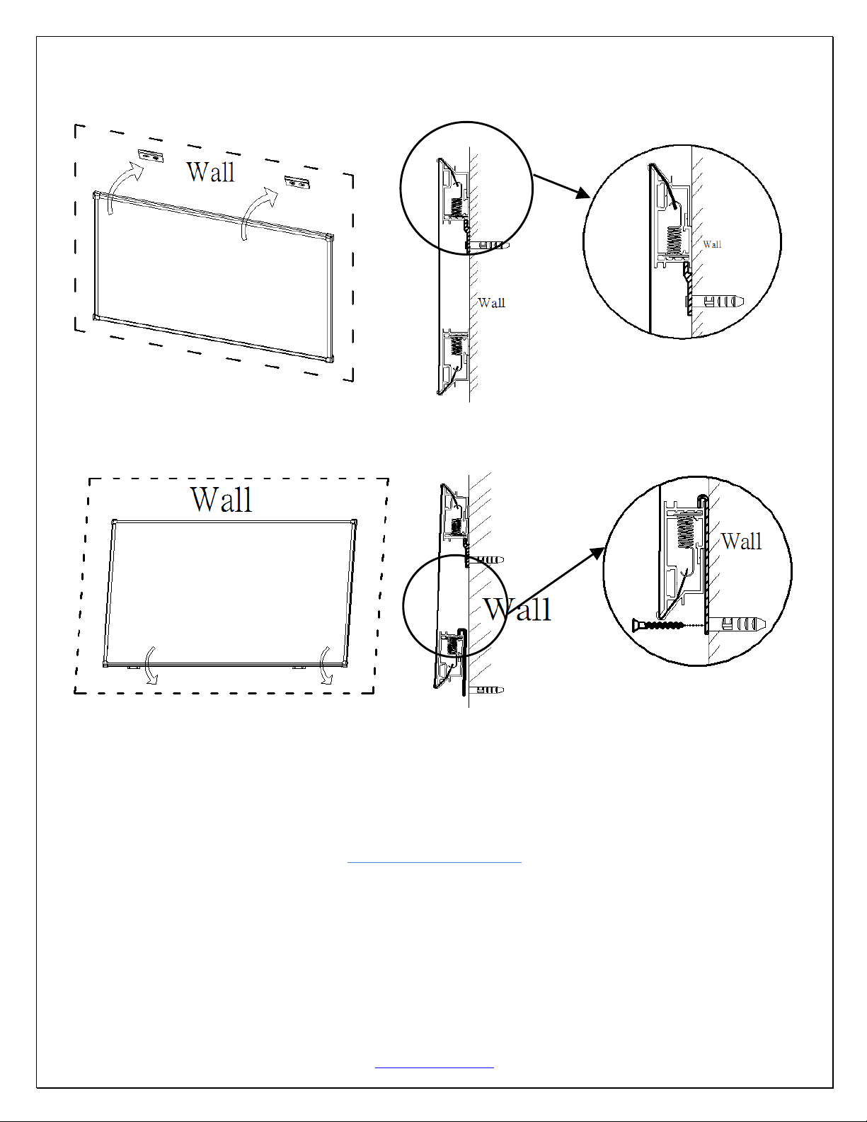
Wall Installation
Step 14: Measure the overall length and height of the frame and drill holes for the top brackets. Line up the wall
brackets with the drilled holes on the installation location and screw them in using a Phillips screwdriver. If not
installing into a structural wood stud, use a hollow wall anchor then screw in the M5x50 wood screws with a
screwdriver. Make sure the brackets are leveled.
6/29/17-JA www.eliteproav.com 9
Step 15: Position the fixed frame screen onto the top wall brackets as shown below and push down at the center
of the top of the frame to secure.
Step 16: With the frame slightly tilted outward; connect the bottom brackets onto the bottom groove of the
frame. Then secure them by screwing onto the wall.
!
!
!
For!Technical!Support!or!an!Elite!ProAV!contact!in!your!area,!visit!
www.eliteproav.com!
 Loading...