

Elite Prime Vision Polar Star Series User Manual
Ambient Light Rejecting Fixed Frame Screen
Polar
Elite Prime Vision,
Polar Star
formulated for environments with minimal control over room lighting. It was designed to enhance picture
color fidelity, and improve contrast levels. The
educational facilities, conference rooms or any applications in which incident light is a factor.
to maintain its projection qualities and o
below for proper maintenance and cleaning.
Use a dry microfiber cloth to remove dust from the screen’s surface.
When cleaning, use a damp microfiber cloth with warm water to remove any marks.
ly pressure when cleaning the surface.
Never attempt to use any solutions, chemicals or abrasive cleaners on the screen surface.
In order to avoid damaging the screen, avoid touching it directly with your fingers, pens/pencils or
any other sharp or abrasive objects.
x 6 pcs (4 top/bottom frame pcs + 2 side frame pcs)
1 pc
x 2 pcs
x4 pcs
pcs
x 8 pcs
x 8 pcs
x 16 pcs
x 60
, which is a reference quality front projection material precisely
is best for family rooms,
ptimum performance, please refer to the list
Note:
sure all parts are
included in your
package before
pr
assemble your
Star™
projection screen.
Star™ Series
User’s Guide
Thank you for choosing the
included is our ISF certified
brightness, offer accurate
In order for the Polar Star™
Never rub or app
Hardware and Parts List
A. Frame Parts
B. Screen Material x
C. Center joint
D. Elbow Joint
E. Wall bracket x 4
F. wood screw
G. Hollow wall anchor
H. M5x15 screw
I. Center Support Bar x 1 -
J. Support joiner x 2 -
K. Fix Plates
Polar Star™ fixed frame projection screen!
™
Polar Star™
2 pcs (depending on model/size)
4 pcs (depending on model/size)
- 180 pcs (depending on model/size)
The screen material
Please make
oceeding to
Polar
fixed frame
Rev041316-DR
www.EPVscreens.com
1
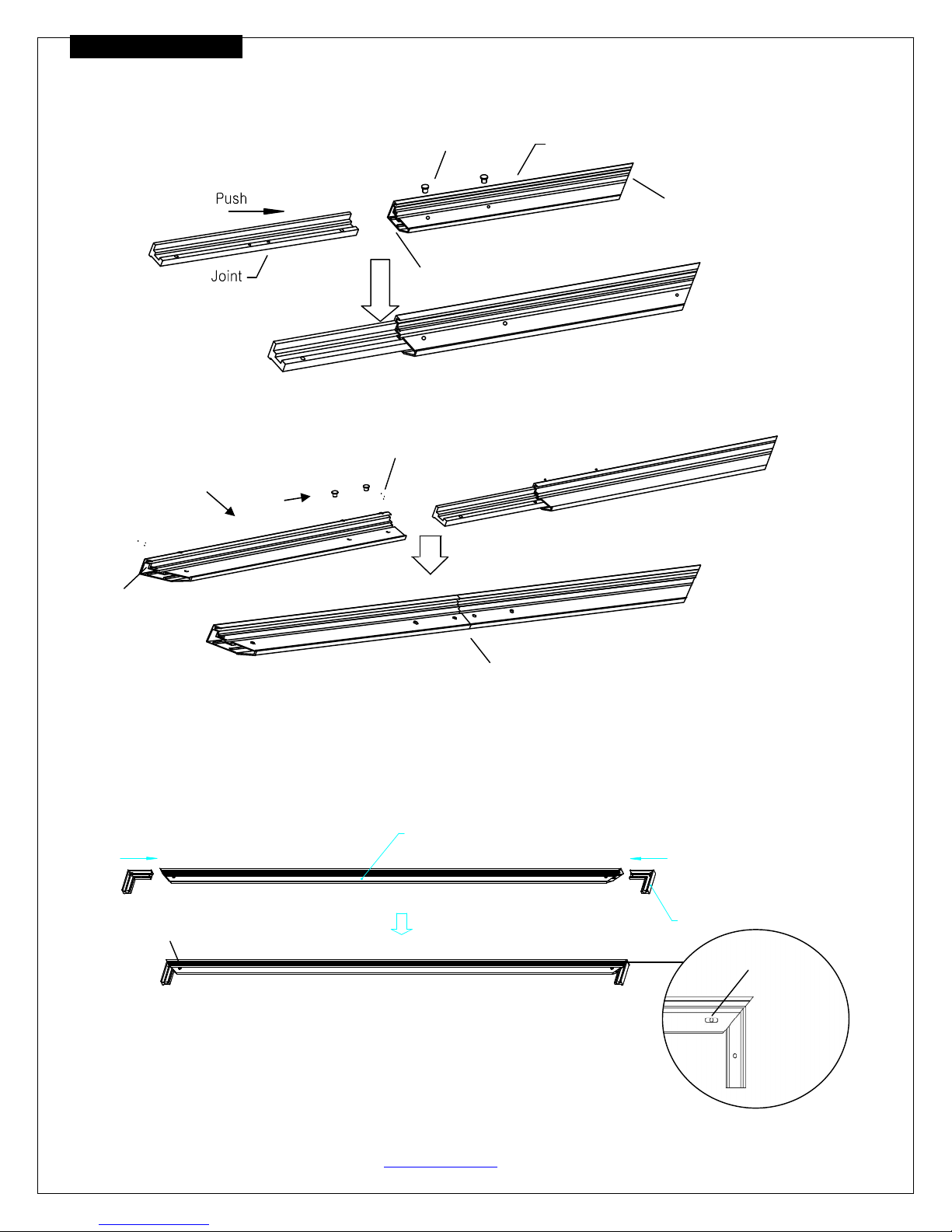
FRAME ASSEMBLY
1. Insert the center joint (c) connector to the horizontal frame piece with bevel connection and flat head,and then
fasten it with two M5x15 screws (h).
M5x15 Screw
Flat head
½ Long Frame
bevel connection
2. Insertthe other horizontal frame piece to thecenter joint connectorand then fasten it with twoM5x15 screws.
½ Long Frame
Push
Flat head
Bevel connection
×2
Horizontal Long Frame
Note: a. 2 long frames should be assembled for a screen.
b. Do not tighten the screws completely until all frame pieces have been assembled correctly.
3. Insert both elbowjoint connectors into the long horizontal frame and then fasten it with twoM5x15
screws(seeFig.1).Then insert the short frames and fasten them with screws (Fig.1.2).
Push
Long frame
Push
M5x15 screws
Joint
M5x15 screws
Rev041316-DR www.EPVscreens.com 2
( fig.1)
Push
Short frame
Short frame
(Fig.1.1)
(Fig.1.2)
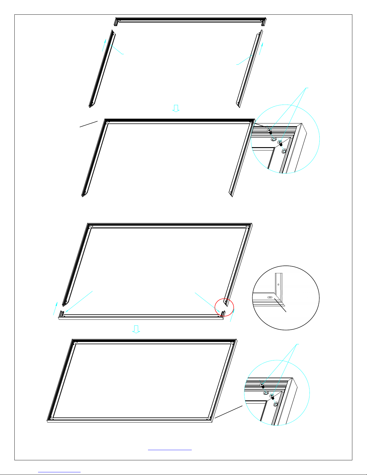
4. Join all four frame parts together following the steps shown below. (Fig.2)
Note: When assembled, please push simultaneously the two ends of the long frames.
Insert the exposed ends of the joint connectors
into the short (vertical) frame and align the four
corners so that they meet at perfect right angles
Push
Push
Push
Screw
M5x15 screws
Screw
( fig.2)
Rev041316-DR www.EPVscreens.com 3
 Loading...