


Acoustically Transparent
Important Safety and Warning Precautions
carefully to ensure proper maintenance and safe
Frame Screen
nging the screen up, please
furniture, ladders, windows, etc., occupy the s
2. Regardless if the screen is hung on or installed into the wall;
ight is supported appropriately by a strong and structurally sound surface
e should.
nt speci
ade of high quality velo
er the screen with a fur
hen cleaning, use a soft cloth moistened with w
pt to use any solutions, che
maging the screen, avoid touching it directly with your fingers,
f reach of small childre
de of high
ater to
een material, never attem
een itself, and never attem
Fixed Frame Projection Screen
& Special Edition A4K
such as power switches, outlets,
e screen.
he proper
inum and should be handled with care.
rom dirt, gri
arks on the fra
u
ousehold sa
inum alloy and should be handled
een material surface.
t to use any solutions, chemicals, or abrasive
th your fingers or sharps/abrasive
Peregrine A4k
Please follow these instructions
Acoustically Transparent Fixed
1. When ha
are used and that the we
large and heavy picture fram
(Please consult a home improveme
3. Frame parts are m
4. When not in use, cov
User’s Guide
make sure that no other objects –
pace designated for your Fixed-Fram
make sure that t
alist for the best advice on installation.)
ur-surfaced alum
niture sheet to protect it f
Series
ty with your
mounting anchors
just as any
me, paint, or any other
impurities.
5. W
surface.
6. Never attem
7. In order to avoid da
other sharp or abrasive objects.
8. Spare parts should be placed out o
CAUTION:
The projection screen frame is ma
Use a soft cloth with warm w
To avoid damaging the scr
cleaners on the scr
objects.
arm water to remove any m
micals, or abrasive cleaners on the screen s
n in accordance with h
-quality alum
remove any spots on the scr
p
pt to touch the screen wi
me or screen
rface.
wri tin g tools, or any
fety guidelines.
with care.
Push
PARTS LIST
1. Frame Parts x 6 pcs
(4 top/bottom frame pcs. + 2 side frame pcs)
9. M5x15Screws x 16 pcs
2. Tension Rods x 6 pcs
(4 top/bottom rods + 2 side rods)
10. User Guide x 1 pc
11. Center Support Bar x 1 – 2 pcs
3. Screen Material x 1 pc
(depending on model/size)
12. Support joiner x 2 – 4 pcs
4. Center joints x 2 pcs
5. Elbow Joints x 4pcs
6. Wall brackets x 2-4pcs
7. Wood Screws x 8pcs
8. Drywall anchors x 8pcs
(depending on model/size)
13. Fix Plates x 50 – 90 pcs
(depending on model/size)
14. Rubber hammer (mallet) x 1 pc
15. Screw driver x 1 pc
Note: Please make sure all parts are included in your package before proceeding to assemble your Elite
Screens fixed frame projection screen.
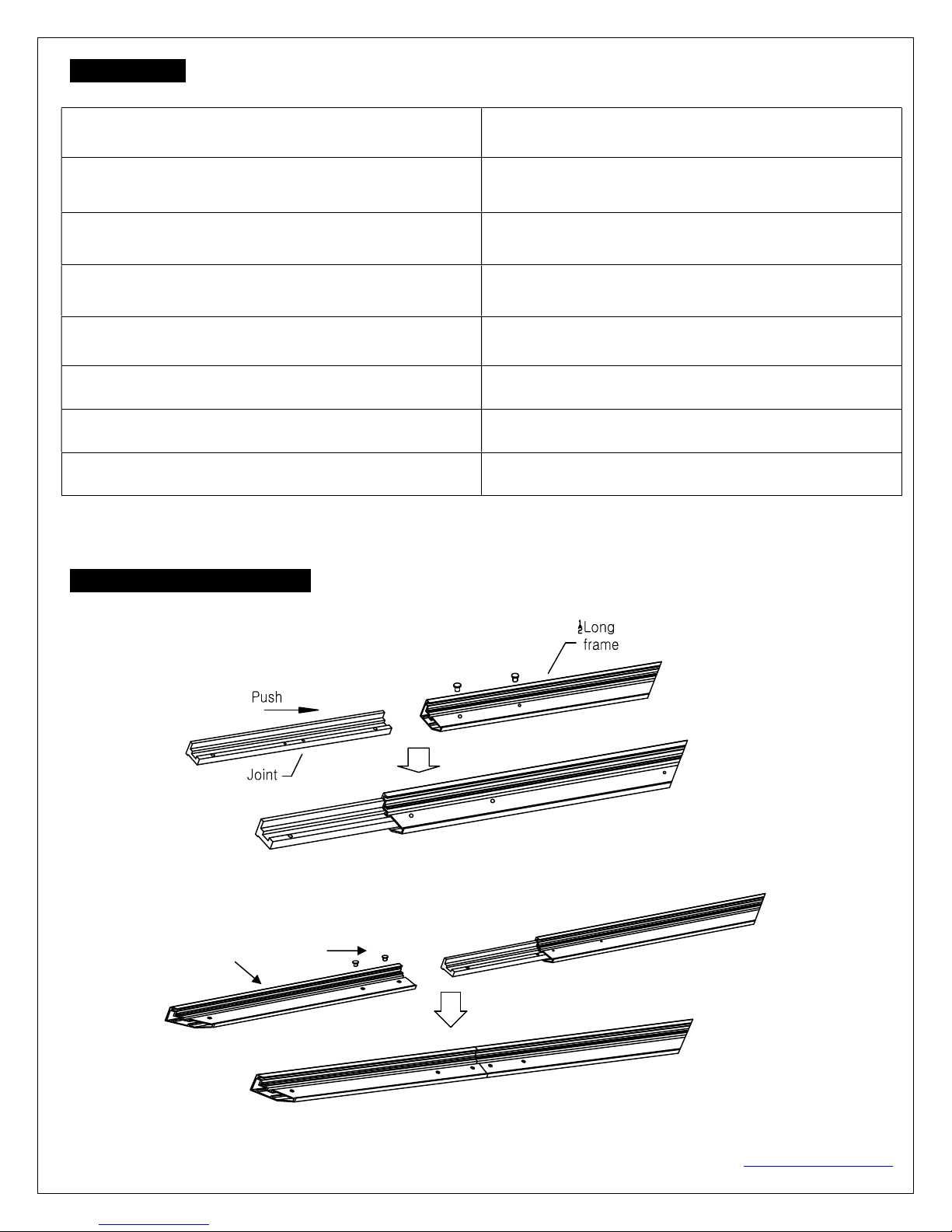
ASSEMBLING THE FRAME
1. Insert the center joint connector to the horizontal frame piece and then fasten it with 2screws.
2. Insert the other horizontal frame piece to the center joint connector and then fasten it with 2 screws.
Make sure the frame piece lines up correctly before you tighten the screws completely.
Rev.082416-MZ 0 www.EPVscreens.com
1/2Long frame
3. Insert both elbow joint connectors into the long horizontal frame (fig.1).
Push
Long frame
Push
Joint
M5×15 Screws
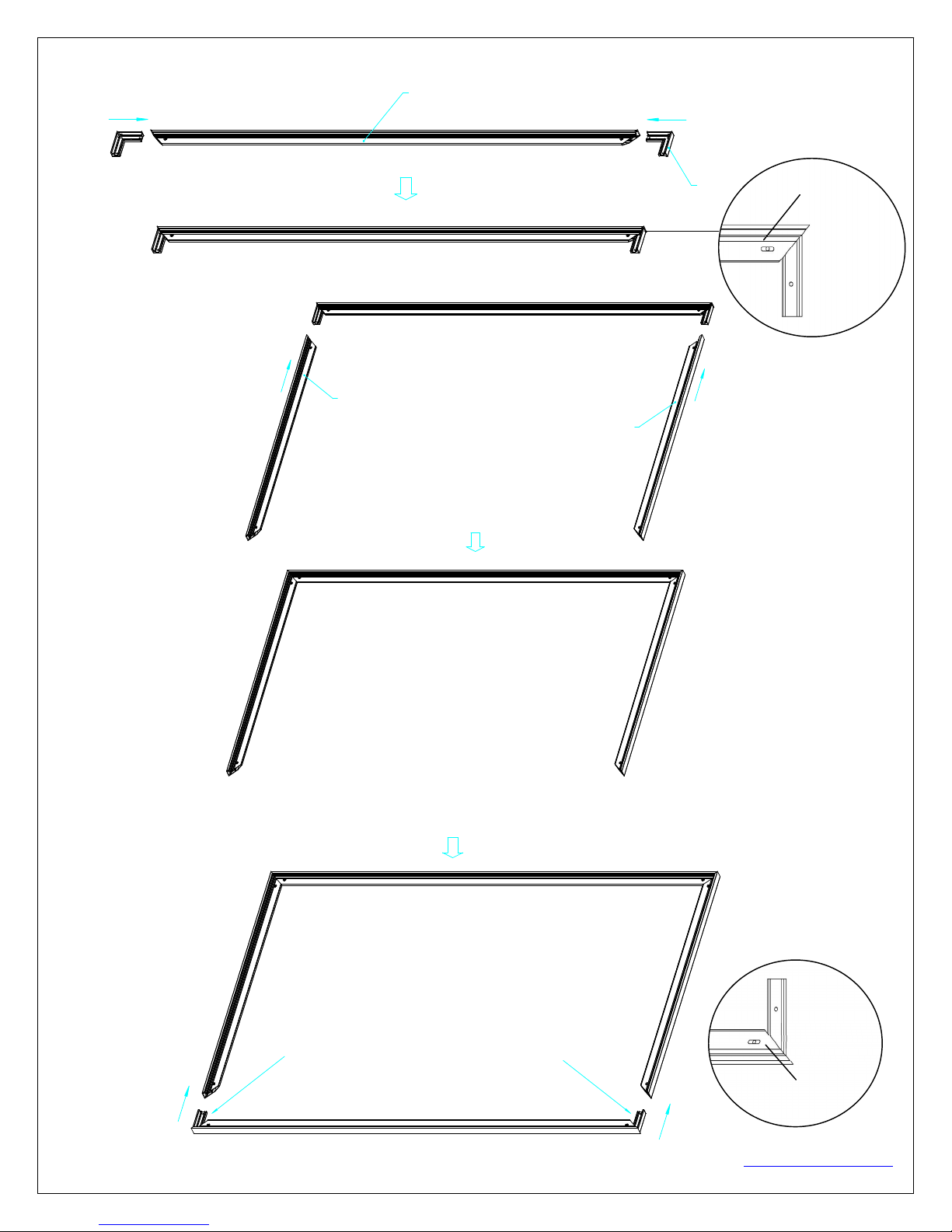
4. Join all four frame parts together following the steps showed below. After making sure that all four corners join
at right angles to form a perfect rectangle, fasten the four angles together by using the (x8) joint screws
included (fig.2).
Push
Short frame
( fig.1)
Push
Short frame
Push
Insert the exposed ends of the joint connectors
into the short (vertical) frame and align the four
corners so that they meet at perfect right angles
M5×15 screws
Push
Rev.082416-MZ 1 www.EPVscreens.com

Push
( fig.2)
5. After making sure that all four corners join at right angles to form a perfect rectangle, fasten the four angles
together by using the (x8) joint screws included (fig.3).
( fig.3)
Screw
ATTACHING THE SCREEN MATERIAL TO THE FRAME_
1. Unroll the screen material and lay it down on a clean surface. Then insert the tension rods separately into the edges
of all four corners of the material (see fig.4).
Tension Rod (Vertical) x 2
Tension Rod (Horizontal) x 4
push
Tension Rod (Horizontal) x 4
Screen Material
push
2. Make sure the screen material and frame are both lying face down on a clean, dry, and non-abrasive surface.
Rev.082416-MZ 2 www.EPVscreens.com
push
push
(Fig. 4)
push
Tension Rod (Vertical) x 2
Screen Material
push

of the
f
rame
D
3. Carefully unroll the material inside the frame. (Fig.5)
Please note the material will be noticeably smaller than the frame, as the material must be stretched to create a sufficient
amount of tension for perfect material flatness.
Notes:
Make note of the label to help distinguish
the back and front side.
Unroll the screen material face down
Keep the screen material as close as
possible to the frame and do not allow it to
scratch against any part of the frame.
ATTACHING THE FIX PLATES_
Stretch the material to the corner and insert the screen material’s edge in the groove of the frame. While one
1.
hand holds the material in place the other hand snaps in the push plate (Fig.6-Fig.7).
(Fig. 6)
Plate
Insert push plate in
(Fig. 7)
Schematic cross section
Frame groove
2. Begin by securing the four corners in the following sequence A→B→C→D (Fig.8).
3. Insert the fix the plates as shown on Fig. 5. Fix plate ① is about 10cm away from the frame’s corner. Fix
plate ② is about 5cm away. (Fig.9)
C
Rev.082416-MZ 3 www.EPVscreens.com
B
(Fig.8)
Screen material edge
A
(Fig.9)

I
L M
P
Tip for attaching the last corner(D):
1. Position yourself left of location ①.
2. Pull the material to the corner of the frame with your hand while your left
hand snaps in the fix plate on location ①
3. Then insert and snap in the fix plate on location②.
4. Next, move and position yourself on location ③,then pull the edge to the
frame and fasten plates on locations③and④.
5. Finally, fasten the last fix plate on location⑤. (Fig.10)
4. Place a fix plate in the center of each side in the following orderE→F→G→H (Fig.11).
①
Pull
②
⑤
③
④
(Fig. 10)
5. Next, fasten a fix plate on the center of each frame side in the following order I→J→K→L→M→N→O→P
as shown in Fig.12.
H
G
(Fig.11)
F
E
J
K
Rev.082416-MZ 4 www.EPVscreens.com
O
N
(Fig.12)

Fasten the remainder of the fix plates in the empty locations in the red markings to complete attaching the screen
BLACK BACKING ATTACHMENT
The purpose of the black backing material is to block out any light penetration that may
cause distortion to the projected image.
into each side of the
The black backing is held in place by the Velcro that is on the fix plates.
Black backing
reflect off of anything mounted
Interval markings reveal the best points for inserting the fix plates
to the lip on the back of the
frame creating a friction hold that will firmly keep the material and
).After the material has been
over the back of the white (Acoustic) material and
eld in place by the Velcro on the fix plates(Fig 1
the Acoustic material and the black backing behind it.
6.
material. (Fig.13)
behind the screen, which can
Fix plates secure
(Fig. 14). The prongs on the fix plates insert
black backing in place (Fig. 15-16
the backing will lay
then be h
(Fig.13)
installed,
7).
(Fig. 14)
CENTER SUPPORT BAR
1. Insert the support joiner
support joiner
Rev.082416-MZ
(Fig. 15)
(Fig. 16)
center support bar to complete assembly.
Center support bar
5
www.EPVscreens.com
(Fig. 17)

Center Support Bar
2. Insert the Center Support Bar into the upper top groove on the back of the frame (not where the fix plate inserts)
with the bottom end near the approximate center point of the frame and place it in at an angle so that both ends of the
bar are in alignment with the groove(Fig. 18 and 19).
Diagonal models 150” and below use 1 x Center Support Bar
Center Support Bar
(Fig. 18)
Diagonal models above 150” require 2 x Center Support Bars
Fixed plate groove
(do not insert here)
Screen material edge
(Fig. 19)
3. Slide the top end of the bar into the top center point location to complete center support bar installation. This will
provide added stability to your frame and added tension to the material.
Rev.082416-MZ 6 www.EPVscreens.com
Remove
push

INSTRUCTIONS
Locate your desired installation location with a stud finder (recommended) and mark the
be installed
with the proper bit size according to the wood screw
with the drilled holes on the installation location and screw them
Note: Use 2 top wall brackets on diago
Position the fixed frame screen onto t
to secure the installation.
The wall brackets allow flexibility
to be
Using both hands finish the installation by pushing the lower portion of the fixed
For a local Elite Screens contact or Technical Support, please visit
20
nal sizes below 135”, and use 3 top wall brackets on
and push down at the center of the
screen to slide to the sides.
frame screen into the lower
INSTALLATION
1.
drill-hole area of
where the screen is to
2. Drill a hole
3. Line up the wall brackets
screwdriver.
diagonal sizes 135” and above
4.
bottom frame
5.
feature as it allows your screen
6.
bracket as shown in Fig 21.
(Fig.
.
s included.
he top wall brackets as shown (Fig. 20)
by allowing the fixed frame
properly centered.
)
in using a Philips
This is an important
(Fig. 21)
www.EPVscreens.com
Rev.082416-MZ
7
www.EPVscreens.com
 Loading...