

ELITEL AH507 Series User Manual

G.SHDSL Router – AH507
User’s Manual

G.SHDSL Router - AH507 Version 1.0
1
Table of Contents
1. PRODUCT OVERVIEW ..............................................................................................1
1.1 P
REFACE
1.2 O
VERVIEW
2. HARDWARE INSTALLATION....................................................................................7
2.1 F
RONT PANEL
2.2 R
EAR PANEL CONNECTORS
2.3 I
NSTALLATION PROCEDURE
3. CONFIGURING WITH CLI..........................................................................................9
3.1 C
ONSOLE SETUP
3.2 M
ENU OVERVIEW
3.3 L
OGIN
......................................................................................................................... 1
...................................................................................................................... 1
LEDS I
NDICATORS
................................................................................. 7
...........................................................................................8
...........................................................................................8
............................................................................................................. 9
.........................................................................................................10
...........................................................................................................................10
3.3.1 Login.....................................................................................................................10
3.3.2 Changing System Password................................................................................10
3.4 S
ETUP
............................................................................................................................11
3.4.1 Main Menu ...........................................................................................................11
3.4.2 System Overview..................................................................................................12
3.4.3 System Operation Mode ......................................................................................12
3.4.4 Bridge Mode.........................................................................................................13
3.4.5 Router Mode.........................................................................................................24
3.5 S
YSTEM MAINTENANCE
...............................................................................................50
3.5.1 Load Factory Default ..........................................................................................51
3.5.2 General Maintenance .......................................................................................... 52
3.5.3 Ping Test...............................................................................................................53
3.5.4 Display Configuration.........................................................................................54
3.5.5 Time Settings........................................................................................................55
3.6 P
ERFORMANCE AND STATISTIC
....................................................................................56
3.6.1 DSL .......................................................................................................................57
3.6.2 ATM ......................................................................................................................58
4. CONFIGURING WITH WEB......................................................................................59
4.1 L
OGIN
...........................................................................................................................59
4.2 W
4.3 S
EB MENUS
ETUP
............................................................................................................................60
.................................................................................................................59
4.3.1 System Information..............................................................................................60
4.3.2 System Operation Mode ......................................................................................61
4.3.3 Bridge Mode.........................................................................................................62
4.3.4 Router Mode.........................................................................................................70
4.4 M
AINTENANCE
.............................................................................................................93
4.4.1 General Maintenance .......................................................................................... 93
4.4.2 Time Settings........................................................................................................94

G.SHDSL Router - AH507 Version 1.0
2
4.4.3 Factory Default....................................................................................................95
4.4.4 Save....................................................................................................................... 96
4.5 P
ERFORMANCE
.............................................................................................................96
4.5.1 DSL Performance & Statistic.............................................................................. 96
4.5.2 ATM Performance & Statistic.............................................................................97
5. UPGRADING FIRMWARE........................................................................................98
5.1 U
PGRADE USING ETHERNET PORT
5.2 U
PGRADE USING SERIAL PORT
APPENDIX..................................................................................................................107
A
PPENDIX
A:I
NSTALL
TFTP
SOFTWARE
............................................................................... 98
.....................................................................................99
.........................................................................107

G.SHDSL Router - AH507 Version 1.0
1
1.
Overview
1.1 Preface
The primary objective of this manual is to help network administrator operate AH507
bridge and router product. Strongly committed to user friendly, this manual will guide the
users step by step to turn the product up and running in the simplest way ever.
1.2 Overview
The AH507 is an ATM based G.SHDSL terminating device enabling the transport of
multi mega bits stream over one or two pair of copper wires using TC-PAM technology.
The unit complies with ETSI and ITU standard including G.991.2, allows full duplex and
operates at speed of 2.3 Mbps over 2-wire, and up to 4.6 Mbps over 4-wire loop. Based
on these standards, the AH507 is interoperable with the majority of DSLAM where
connections to the ATM core switches are made.
Each AH507 supports a wide range of protocols and features, including IP routing, pointto-point protocol (PPP), ATM, frame relay, and standard bridging protocols. Embedded
with FRF.5 and FRF.8 Frame Relay to ATM Inter-working function, the AH507 thus
offers simultaneous connection of legacy Frame Relay equipment as well as routed IP
services to high speed ATM switch.
The port-based Virtual Server or host-based DMZ features allow local servers to be
exposed to the Internet for providing services such as File Transfer, Mailing, HTTP or
Telnet. In-built ACL (Access Control List) feature enables the unit to examine the
network traffic's Source IP address, Destination IP address, and IP protocol type to
decide if the IP traffic is allowed to pass through it.
Unlike simple Internet sharing device, the AH507 is a true firewall router, using stateful
packet inspection to defend against Denial of Service (DoS) attacks.
The VPN Pass Through feature supports the pass through of IPSec, L2TP or PPTP
tunnel for a secured transmission between two VPN endpoints
Remote management function allows user to be able accessing the AH507 via Web,
Telnet for configuration, or TFTP for firmware upgraded. It offers the embedded DHCP
server, which helps system administration manage the IP address network in the easiest
way ever.

G.SHDSL Router - AH507 Version 1.0
2
Features
SHDSL Access
Support 2/4 wires SHDSL and meet ITU-T G.991.2 standard.
ATM Protocols
ATM Multi-protocol Encapsulation over ATM Adaption Layer 5 (RFC 1483): Logical
Link Control (LLC) encapsulation routed modes
Virtual Circuit:
Terminates ATM Permanent Virtual Circuit (PVC) with ATM Adaptation Layer 5
(AAL5); Allows manual configuration of Virtual Path Identifier (VPI) and Virtual
Channel Identifier (VCI) for the full range of addresses supporting up to 12 Multiple
PVCs
Frame Relay Support
ANSI T1.617 and ANSI T1.618 Annex D LMI and Annex A LMI,
TCP/IP and PPP Support
IEEE 802.1d Transparent Bridging and Spanning Tree
TCP/IP with RIPv1, RIPv2 and static IP routing
PPP over ATM (RFC 2364), PPP over Ethernet, IP over ATM
Frame Relay (RFC 1490)
Network Address Translation (RFC 1631) DHCP Client, Server and Relay
DMZ support
Port Mapping/Forwarding
Security
Firewall with Stateful Packet Filtering
PAP and CHAP for PPP user authentication
Multiple IP SEC/L2TP/PPTP pass through
Protection against Denial of Service attacks
Configuration and Management
Management via local console, GUI, Telnet or embedded SNMP agent.
Software upgrade via TFTP/HTTP
Diagnostic Test includes DSL, OAM, Network Connection, Ping Test

G.SHDSL Router - AH507 Version 1.0
3
Network Interface
SHDSL Link
Standard: SHDSL per ITU-T G.991.2
Line code: TC-PAM, Support ANSI (ANNEX A) and ETSI (ANNEX B)
Data rates:
Automatic rate adaptive and manual programmable data rate
n x 64 kbps:
2.304 Mbps: 2-wire (line rate: 2.320 Mbps)
4.64 Mbps: 4-wire (line rate: 4.640 Mbps)
Connector: RJ-11
Timing Source
Tx timing:
Note:CO fixed Internal clock
RT fixed Recovered clock
ATM Specification
ATM Adaptation: AAL5
AAL5 Encapsulation:
RFC 1483 "Multiple Protocol over AAL5"
RFC 2364 "PPP over AAL5"
ATM services:
CBR, UBR ,rt-VBR / nrt-VBR
F4/F5 OAM cells as per I.610
Frame Relay Support:
FRF.8 “Frame Relay/ATM Service Inter-Working
FRF.5 “Frame Relay/ATM Network Inter-Working
IP over Frame Relay

G.SHDSL Router - AH507 Version 1.0
4
User Interfaces
Data port
Termination: V.35
Rate: N x 64K bps
Protocol Support:
Frame Relay:
Transparent data over ATM AAL5
BVI: Bridge Visual Interface ( optional )
Tunneling: Optional HDLC encapsulation over IP (HDLC, or HDLC Cisco)
Clock source: V.35, Internal
Connectors: DB25, DCE
Ethernet Interface
Standard: IEEE 802.3 / IEEE 802.3u
Interface: IEEE 802.3/802.3u 10/100 Base-T
Bridging Capability: Complied with IEEE 802.1d transparent bridge
Supports up to 128 MAC addresses learning
Supports bridge filtering function
Connection Type: : RJ-45
Management
Management Interfaces
Menu-base
Web-base
SNMP/Telnet
Management function:
LED status monitoring on DSL, V.35 and LAN.
Performance monitoring of DSL and ATM
Event (SNMP Trap)
Supervisory Port
Devices connected: DCE port: ASCII terminal
Interface: V.24/RS-232, Async
Baud rate: Setting to 115.2 kbps, 8 data bits, 1 stop bits, on-parity
Connector: DB-9
Compliance
ITU-T: I.361, I.362, I.363, I.364, I.365.1, I.413, I.555, I.610

G.SHDSL Router - AH507 Version 1.0
5
FRF: FRF.5, FRF.8
Power
AC 100 to 230 VAC (Build-in AC Connector)
DC -42 to -56 VDC
AC+DC: AC 100 to 230 VAC, DC -42 to -56 VDC, field selectable
Ordering: AH507-i1-i2-i3
AH507-i1-i2-i3
i1 Specify the number of SHDSL loop
02
i2 Specify the V.35 FR Serial port
I3 Specify the power source.
2 wires on SHDSL transmission
04
4 wires on SHDSL transmission
F
V.35 Frame Relay
X
No FR specified
A
AC power
D
DC power
AD
AC+DC power
G.SHDSL Router - AH507 Version 1.0
6
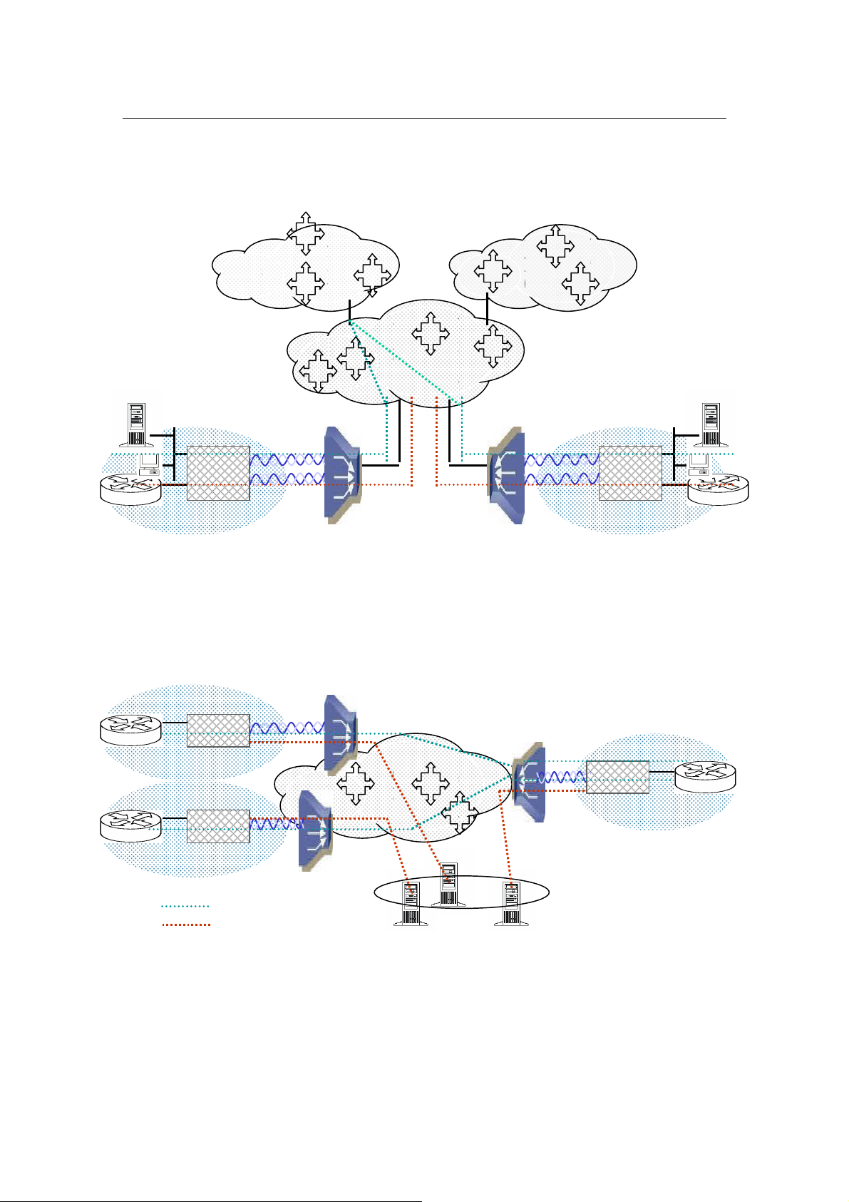
Transporting Frame Relay and IP traffic over ATM
SHDSL
1
Transporting Frame Relay over ATM
Site 1
Router
IP Network
Frame Relay Network
ATM Core
ATM Switch
IP
AH507
AH507
FR
Frame Relay CPE
Site 1
SHDSL 2
DSLAM
DSLAM
SHDSL 2
Site 2
FR
AH507
ATM Switch
AH507
ATM Switch
ATM Core
AH507
Site 2
Legend:
IP on VC1
SNMP on VC 2
SNMP Stations
IP
FR
Frame Relay CPE
FR Router
G.SHDSL Router - AH507 Version 1.0
7
2.
Installation
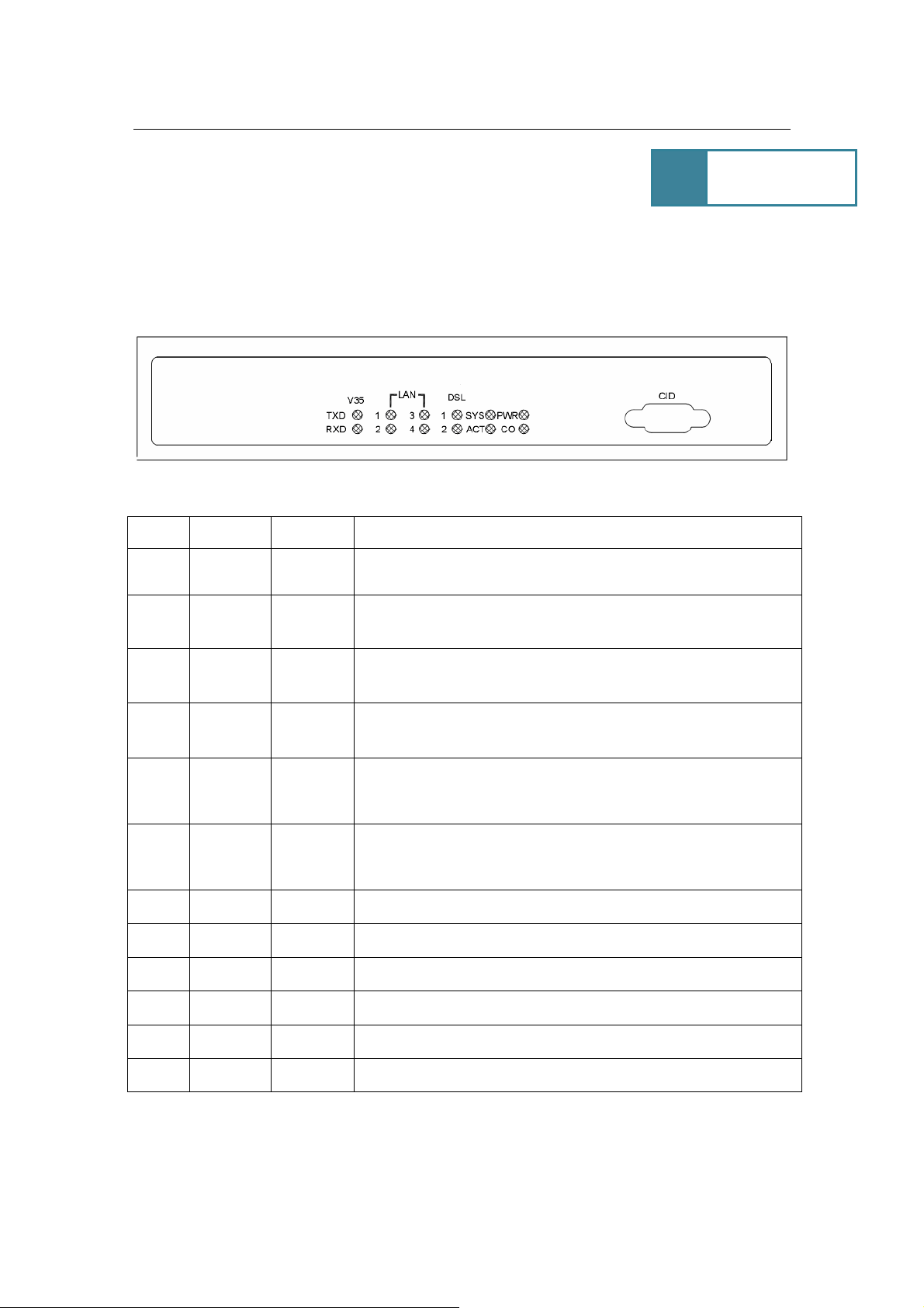
2.1 Front Panel LEDs Indicators
There are eight LED indicators on the front panel of AH507. They show the statuses of
the device.
The functions of LED indicators are described in the following table:
LED Color Status Meaning
PWR Green
SYS Green
Steady
Off
Steady
Off
The device is on.
The device is off.
The device is on and functioning properly.
The device is booting or Off
ACT Green
CO Green
DSL1 Green
DSL2 Green
LN1 Green Steady Link 1 – The LAN connection is successfully established.
LN2 Green Steady Link 2 – The LAN connection is successfully established.
LN3 Green Steady Link 3 – The LAN connection is successfully established.
LN4 Green Steady Link 4 – The LAN connection is successfully established.
TXD Green
RXD Green
Blinking
Off
Steady
Blinking
Off
Steady
Blinking
Off
The device is sending or receiving data
There’s no data sending or receiving.
The device is Sync Status.
The link is synchronizing - this may take several minutes.
The device is unplugged or disconnected.
The device is Sync Status.
The link is synchronizing - this may take several minutes.
The device is unplugged or disconnected.
G.SHDSL Router - AH507 Version 1.0
8
Power Adapter
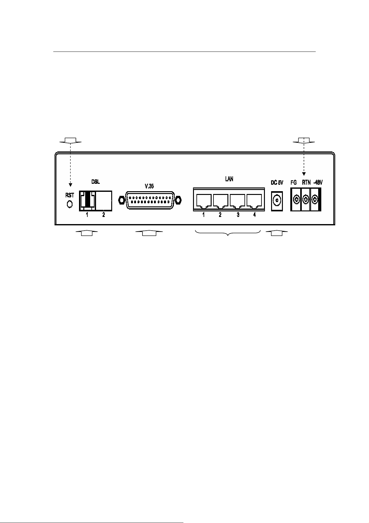
2.2 Rear Panel Connectors
The rear panel connectors connecting the device to the LAN and xDSL network are
illustrated as follows.
Reset
-48VDC
Phone Line
(Showing 2 wires SHDSL)
RJ-11
100/100M LAN V.35 DB25
110VAC / 220 VAC~5VDC
Figure 1: Rear Panel and Installation
2.3 Installation Procedure
Step 1. - Use RJ-11 cable to connect the device to DSL line.
Step 2. - Use MR34 to DB25 adaptor to connect the V.35 serial port.
Step 3. - Use RJ-45 cable to connect the device and the PC which has the Network
Interface Card (NIC) installed. If you want to connect to an external hub, you have to
use the RJ-45 cross-over cable.
Step 4. - Plug in the Power adaptor to the DC Power socket of the device, then connect
the Power adaptor to the AC outlet.
G.SHDSL Router - AH507 Version 1.0
9
DSLAM / ISP
Internet
3. Configuring
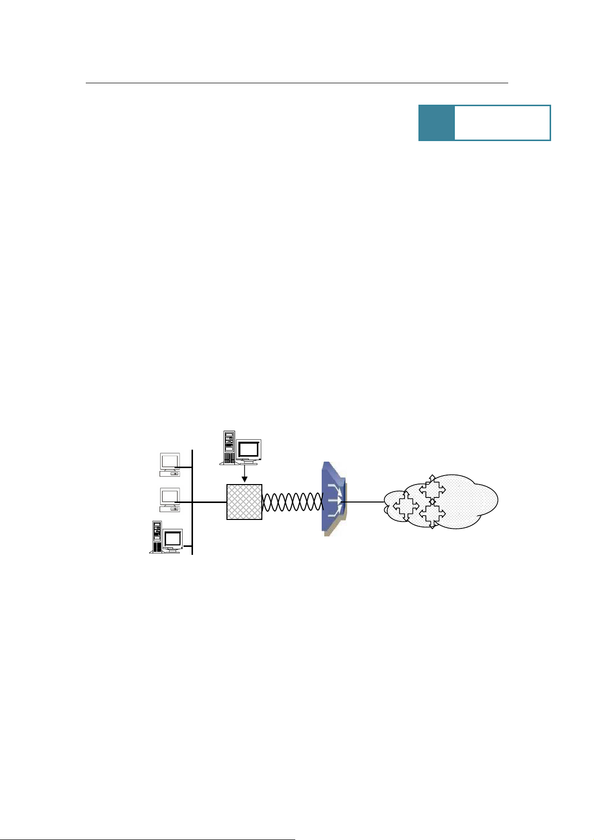
3.1 Console Setup
Step 1: Connect computer to the device through the console port as shown in Front
Panel.
Step 2: Open the terminal emulator software (like Hyper-Terminal on Microsoft Windows
machine, or “ Minicom” on Linux machine), then select the proper COM port for the
connection. Set the terminal and port to the following parameters:
- Terminal Mode: VT-100
- Baud rate : 115200 bps
- Data bits : 8
- Parity : None
- Stop bits : 1
- Flow Control : None
Turning on the AH507, then after few seconds of machine initialization, the system
management terminal will display the login screen. Details see section 3.3.1.
Emulator Terminal
VT-100
Corporation LAN
AH507
Figure 2: Console Setup

G.SHDSL Router - AH507 Version 1.0
10
3.2 Menu Overview
You can refer to Main Menu, see section 3.4.1.
3.3 Login
3.3.1 Login
- Default Password: admin
3.3.2 Changing System Password
You can change the system password by following steps:
Login to the Main Menu:
Step1. - Press ‘E’ to open menu ‘System Maintenance’
Step 2. - Press ‘B’ to open menu ‘General Maintenance’
Step 3. - Press ‘C’ to enter the old password.
Step 4. - Press ‘D’ to enter a new password.
Step 5. - Press ‘E’ to re-type the new password to confirm.
Step 6. - Press ‘ENTER’ key to update.
NOTE: To cancel the setup, press the key ‘ESC’.

G.SHDSL Router - AH507 Version 1.0
11
3.4 Setup
3.4.1 Main Menu
It contains all the submenus of management system terminal in which the configuration
of device can be set.
G.SHDSL Router - AH507 Version 1.0
12
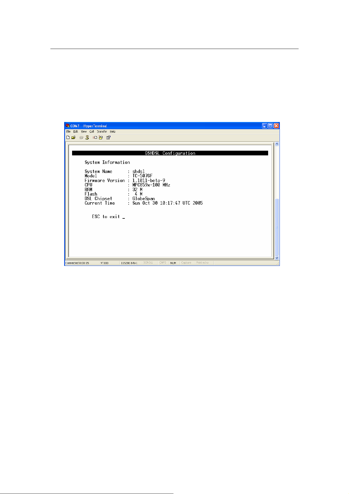
3.4.2 System Overview
From Main Menu, press ‘A’ to open menu System Overview.
In this menu, it shows the current system information such as: System Name, Model,
Firmware Version, CPU, RAM, Flash size, DSL chipset and Current Time.
3.4.3 System Operation Mode
You can set System Operation Mode: BRIDGE or ROUTER from two different menus:a. In menu ‘Quick Setup’:
From Main Menu,
Step 1: - Press ‘B’ - to open menu ‘Quick Setup’
Step 2: - Press ‘A’ - to select item Operation Mode
Step 3: - Press ‘Space Bar’ - to toggle between BRIDGE / ROUTER mode
Step 4: - Press ‘Enter’ - to update the system operation mode
b. In menu ‘System Setup’
From Main Menu,
Step 1: - Press ‘C’ - to open menu ‘Basic Configuration’
Step 2: - Press ‘A’ - to open menu ‘System Setup’
Step 3: - Press ‘A’ - to select item Operation Mode
Step 4: - Press ‘Space Bar’ - to toggle between BRIDGE / ROUTER mode
Step 5: - Press ‘Enter’ - to update the system operation mode
G.SHDSL Router - AH507 Version 1.0
13
Figure
3: Bridge Mode
-
Application of
AH507
: Inter
net Access
DSLAM / ISP
Internet
AH507
AH507
ATM
NOTE: You must press ‘Enter’ to update system configuration after selecting the
operation mode.
3.4.4 Bridge Mode
In Bridge mode, AH507 provides frame forward services between two or more LANs. It
forwards frames based on the MAC (Medium Access Control) addresses which is
hardware-level of NICs (Network Interface Card)
The operation mode of the system must set to BRIDGE Mode. To change the mode,
please see the section 3.4.3. The following sections will help you to do configuration the
device in BRIDGE mode by using the system management terminal.
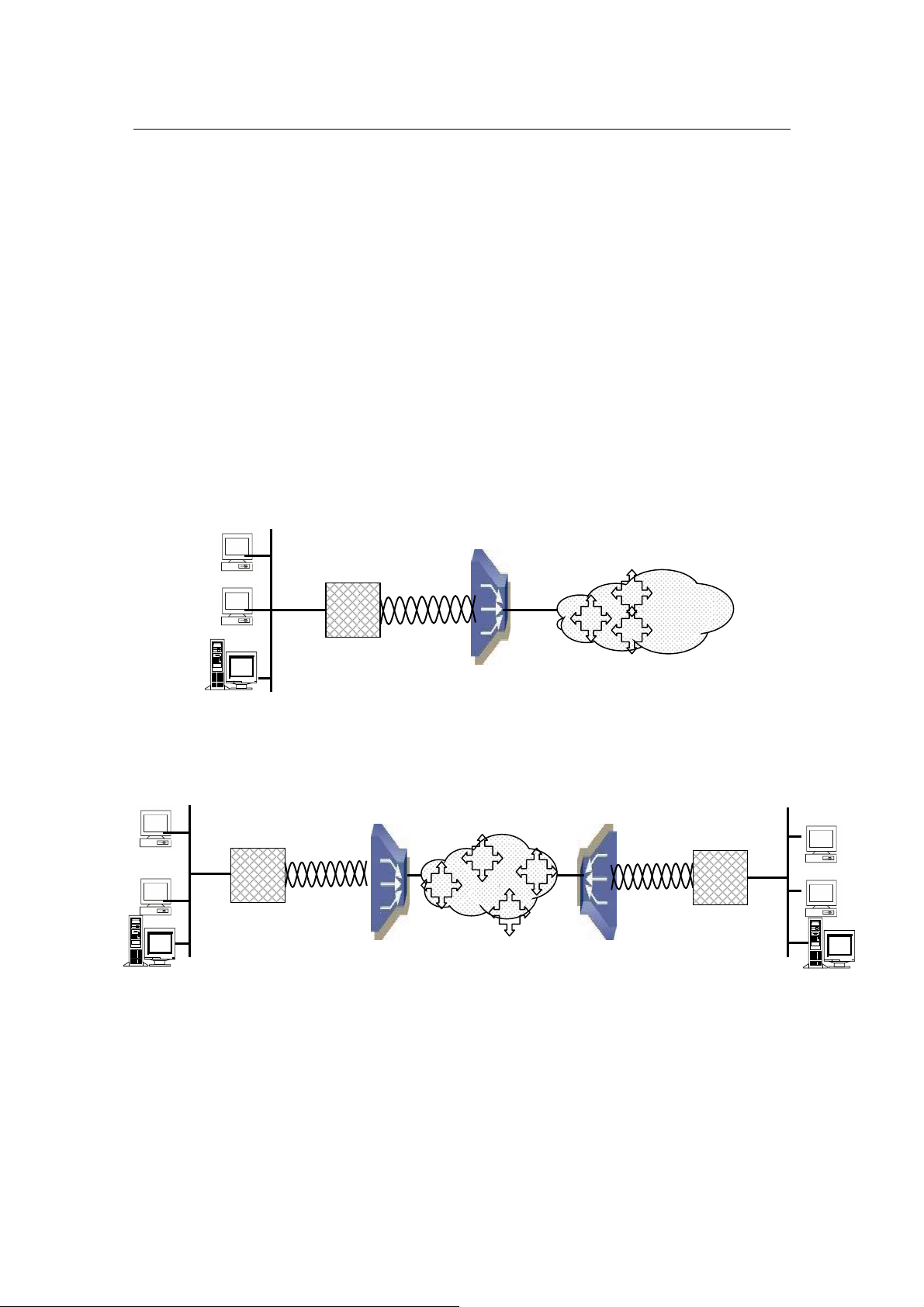
The application of the G.SHDSL Modem in Bridge Mode are illustrated in the following
figures
AH507
Corporation LAN
Corporation LAN
IP Address
Bridge
VPI/VCI
IP Address
VPI/VCI
Bridge
Figure 4 Bridge Mode - Application of AH507: LAN-to-LAN
Branch Office LAN
VPI/VCI
Bridge
IP Address
G.SHDSL Router - AH507 Version 1.0
14
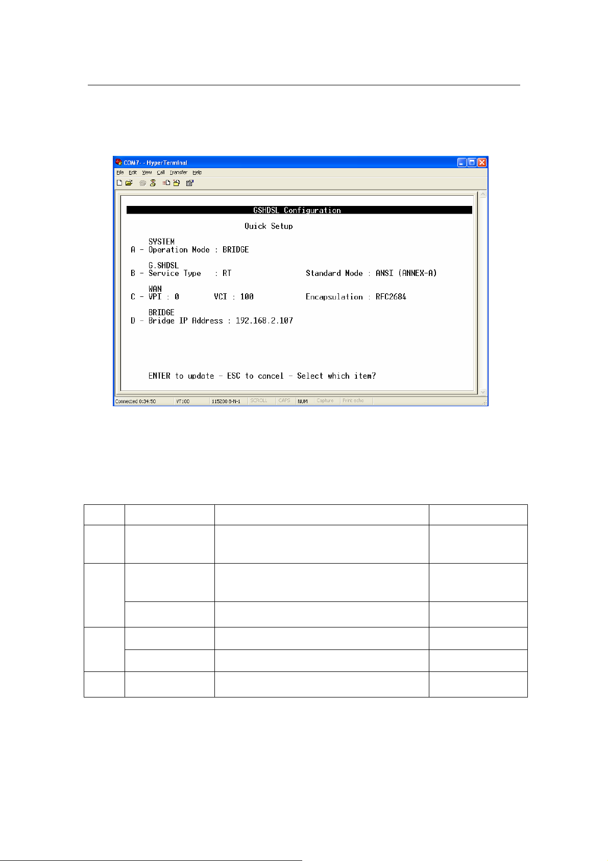
3.4.4.1 Quick Setup:
From Main Menu, press ‘B’ to open menu ‘Quick Setup’
Using this setup, the device can be quickly configured and operated properly. The WAN
configuration is for the first Virtual Circuit ( VC 1 ) in twelve VC set available in the device.
The details of the items are described in the following table:
Item Field Name Description Value
A Operation Mode
Service Type
B
Standard Mode Physical standard mode.
VPI Virtual Path Identifier, given by ISP. 0 - 16
C
VCI Virtual Channel Identifier, given by ISP. 33 - 4096
Bridge IP
D
Address
System operation mode. Press ‘Space
Bar’ to select the setting.
System service type. System can be
operated as RT or COT type. Press
‘Space Bar’ to select the setting.
The device IP address. i.e ‘192.168.0.2’
BRIDGE /
ROUTER
Default: BRIDGE
RT / COT
Default: RT
ETSI / ANSI
Default: ETSI
G.SHDSL Router - AH507 Version 1.0
15
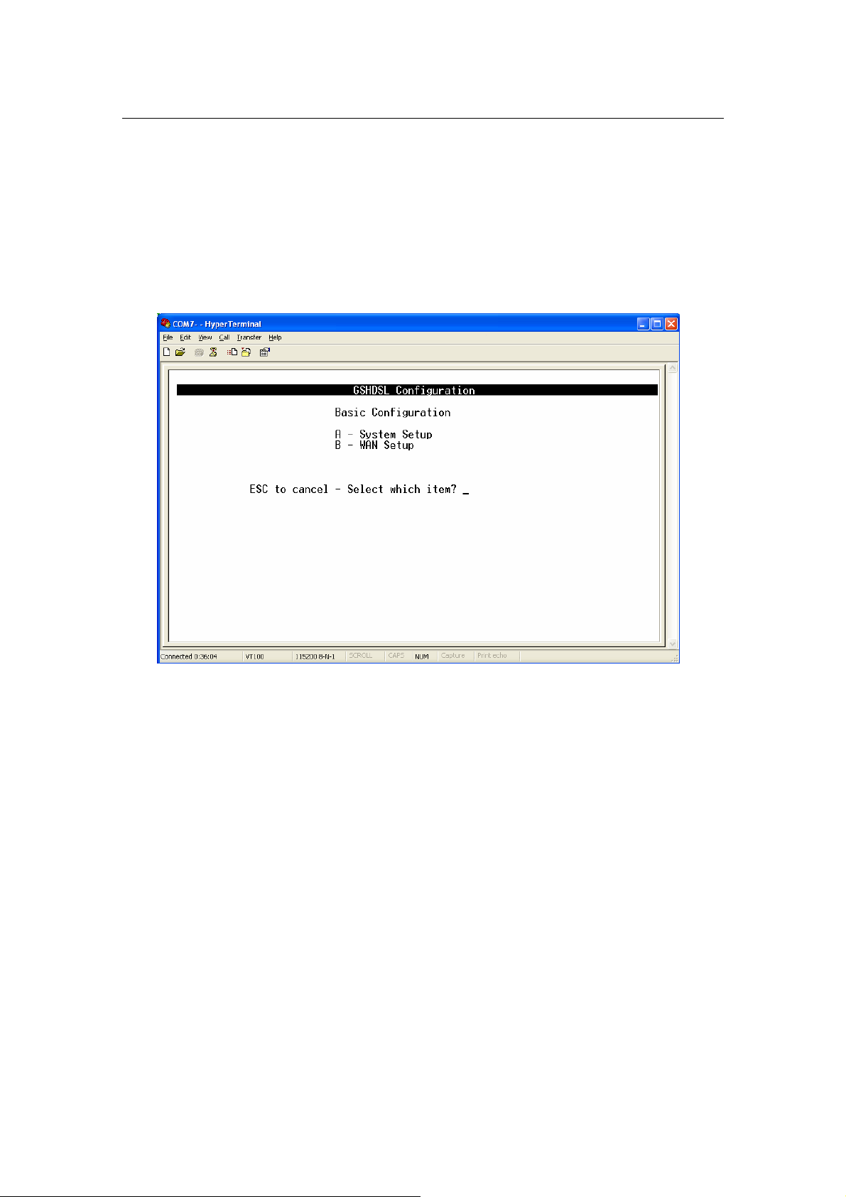
3.4.4.2 Basic Configuration:
From Main Menu,
- Press ‘C’ to open menu ‘Basic Configuration’.
In menu Basic Configuration, the system can be configured in submenus: System Setup
and WAN setup.

G.SHDSL Router - AH507 Version 1.0
16
System Setup
From Main Menu,
- Press ‘C’ to open menu ‘Basic Configuration’.
- Press ‘A’ to open menu ‘System Setup’
In menu System Setup, it contains the system related configuration such as: operation
mode, service type, physical standard mode, Data Rate mode and so on.
The details of the items are described in the following table:
Item
A Operation Mode
B
C Data Rate Mode
D* Range
E
Note: * applicable for Data Rate FIXED mode only
Field Name Description Value
System operation mode. Press ‘Space Bar’
to select the setting.
System service type. System can be
Service Type
Standard Mode
ETHERNET
Connectivity
operated as RT or COT type. Press ‘Space
Bar’ to select the setting.
Physical standard mode. Press ‘Space Bar’
to select the setting.
Data transferred rate mode. Press ‘Space
Bar’ to select the setting.
Date rate range.
In Adaptive mode, the data rate can be
changed in the range 192~2304 kbps.
In Fixed mode, it is set in the range 64~2304
kbps. Press ‘Space Bar’ to select the setting.
Specify the operation mode of LAN port.
BRIDGE / ROUTER
Default: BRIDGE
RT / COT
Default: RT
ETSI / ANSI
Default: ETSI
ADAPTIVE / FIXED
Default: ADAPTIVE
ADAPTIVE: 192~2304
FIXED: 64 - 2304
Auto-Negotiation/10M
half/10M full/100M
half/100M full
G.SHDSL Router - AH507 Version 1.0
17
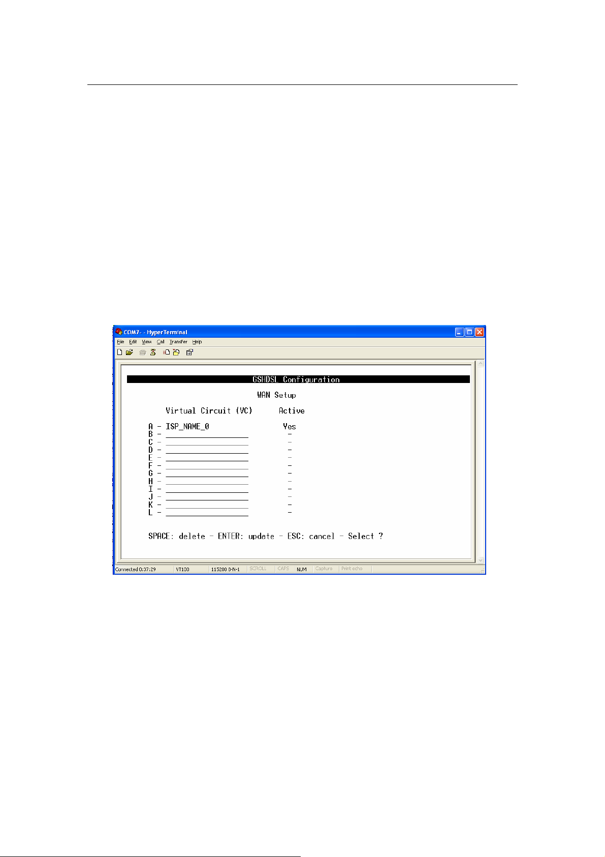
WAN setup
From Main Menu,
- Press ‘C’ to open menu ‘Basic Configuration’.
- Press ‘B’ to open menu ‘WAN Setup’
In menu WAN Setup, it shows the list of Virtual Circuits (VCs) and their statuses.
If a VC is already configured then it displays its name as a identification, otherwise it
displays a underscore line.
If a VC is already activated, then in the field ‘Active’, it displays the word ‘Yes’, otherwise
it displays a dash.
G.SHDSL Router - AH507 Version 1.0
18
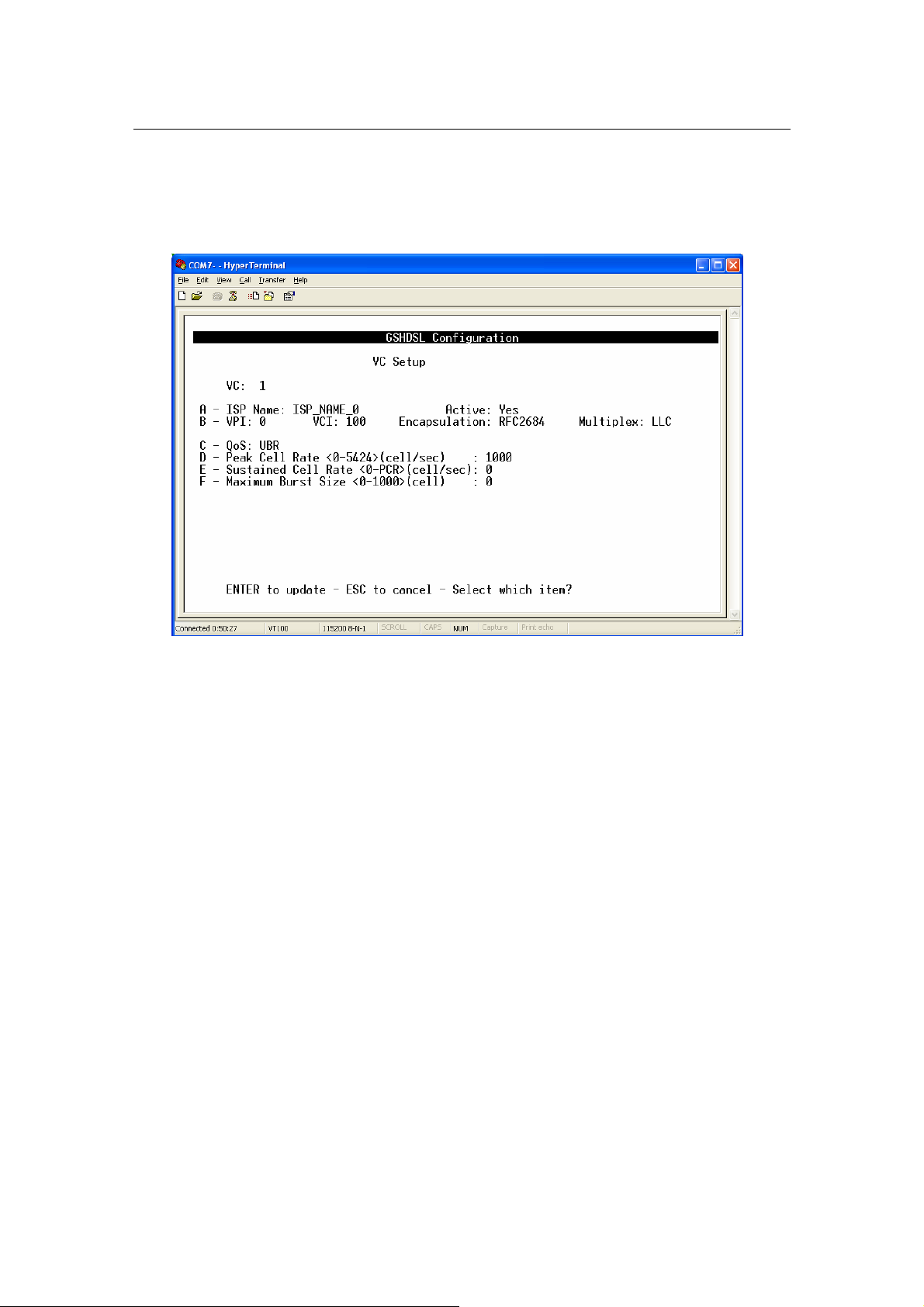
1) To setup VC configuration,
- Press any key ‘A’ to ‘L’ for an appropriate VC, i.e ‘A’ for VC 1, ‘B’ for VC 2...

G.SHDSL Router - AH507 Version 1.0
19
2) To Delete VC configuration,
- Press ‘Space Bar’, then follow the instructions in the bottom line.
The details of the items are described in the following table:
Item Field Name Description Value
A ISP Name ISP Name Max. 18 characters
B VPI Virtual Path Identifier, given by ISP 0 - 16
VCI Virtual Channel Identifier, given by ISP 33 - 4096
Encapsulation Encapsulation type Always set RFC2684
Header to identify the protocol that Virtual
Multiplex
C QoS
Peak Cell Rate
D
(PCR)
Sustained Cell
E
Rate (SCR)
Maximum Burst
F
Size (MBS)
Circuit being carrying.
LLC: Logical Link Control Multiplexing
VCMUX : VC-based Multiplexing
By press ‘Space Bar’ to select the setting.
Quality of Services
UBR: Unspecified Bit Rate.
CBR: Constant Bit Rate.
rt-VBR: Real-Time Variable Bit Rate.
nrt-VBR: Non-Real-Time Variable Bit
Rate.
Press ‘Space Bar’ to select the setting.
The maximum transmission rate. 0 - 5424
The Transmission rate in a burst traffic.
Maximum number of transmission cell at
the peak rate.
LLC / VCMUX
Default: LLC
UBR / CBR / rt-VBR /
nrt-VBR
Default: UBR
0 - PCR
0 - 1000
G.SHDSL Router - AH507 Version 1.0
20
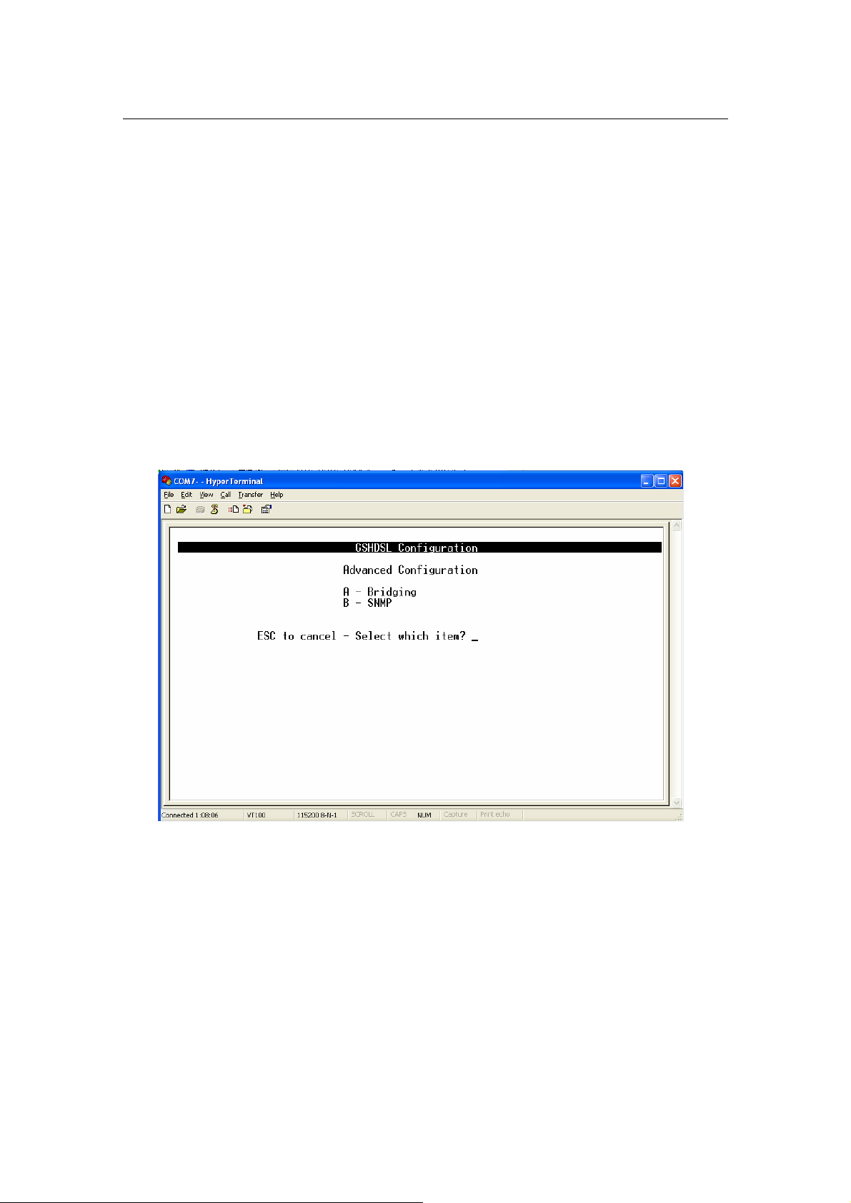
Bridging IP address, Spanning Tree, Priority
, SNMP
3.4.4.3 Advanced Configuration:
From Main Menu,
Press ‘D’ to open menu ‘Advanced Configuration
In submenu Bridging and SNMP under menu Advanced Configuration, it
will help you to configure the system related information such as:
G.SHDSL Router - AH507 Version 1.0
21
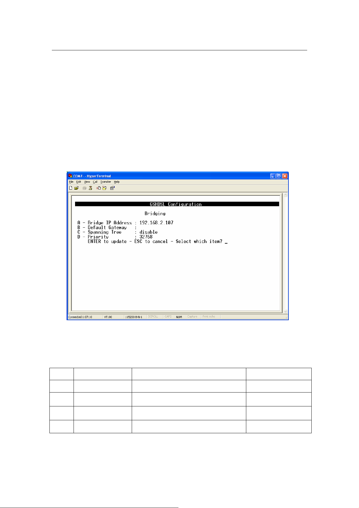
Bridging
From Main Menu,
Press ‘D’ to open menu ‘Advanced Configuration
Press ‘A’ to open menu ‘Bridging’
The details of the items are described in the following table:
Item Field Name Description Value
A Bridge IP Address Bridge IP Address i.e: ’192.168.0.2’
B Default Gateway
C Spanning Tree
D Priority Specify the priority. 0-65535
Specify Default Gateway address of the
unit.
Spanning Tree Learning Bridge Protocol.
Press ‘Space Bar to select the settings.
None
Disable/Enable
Default: Disable
G.SHDSL Router - AH507 Version 1.0
22
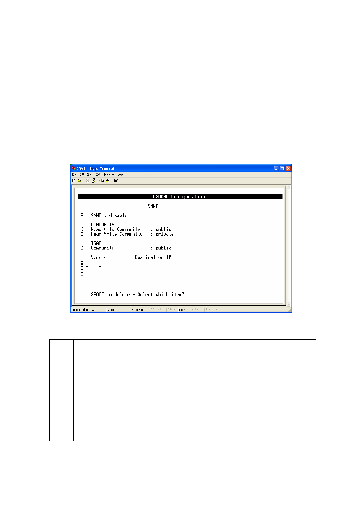
SNMP
From Main Menu,
Press ‘D’ to open menu ‘Advanced Configuration
Press ‘B’ to open menu ‘SNMP
The details of the items are described in the following table:
Item Field Name Description Value
A SNMP
B Read-Only Community
C Read-Write Community
D TRAP Community
E-H Version
Disable or Enable the SNMP management
feature.
Specify the community name of external
SNMP Managers allowed with access level
of “ Read “ to the unit’s MIB.
Specify the community name of external
SNMP Managers allowed with access level
of “ Read & write “ to the unit’s MIB.
Specify the community name of external
SNMP Managers allowed to receive the
TRAP message.
Specify TRAP version and destination IP
address that the TRAP message is intended
Disable/Enable
Default: Disable
Public
Private
Public
None

G.SHDSL Router - AH507 Version 1.0
23
for.
G.SHDSL Router - AH507 Version 1.0
24
WAN
Remote
LAN
LAN
DSLAM / ISP
LAN
Internet
VPI/V
CI
AH507
AH507
ATM
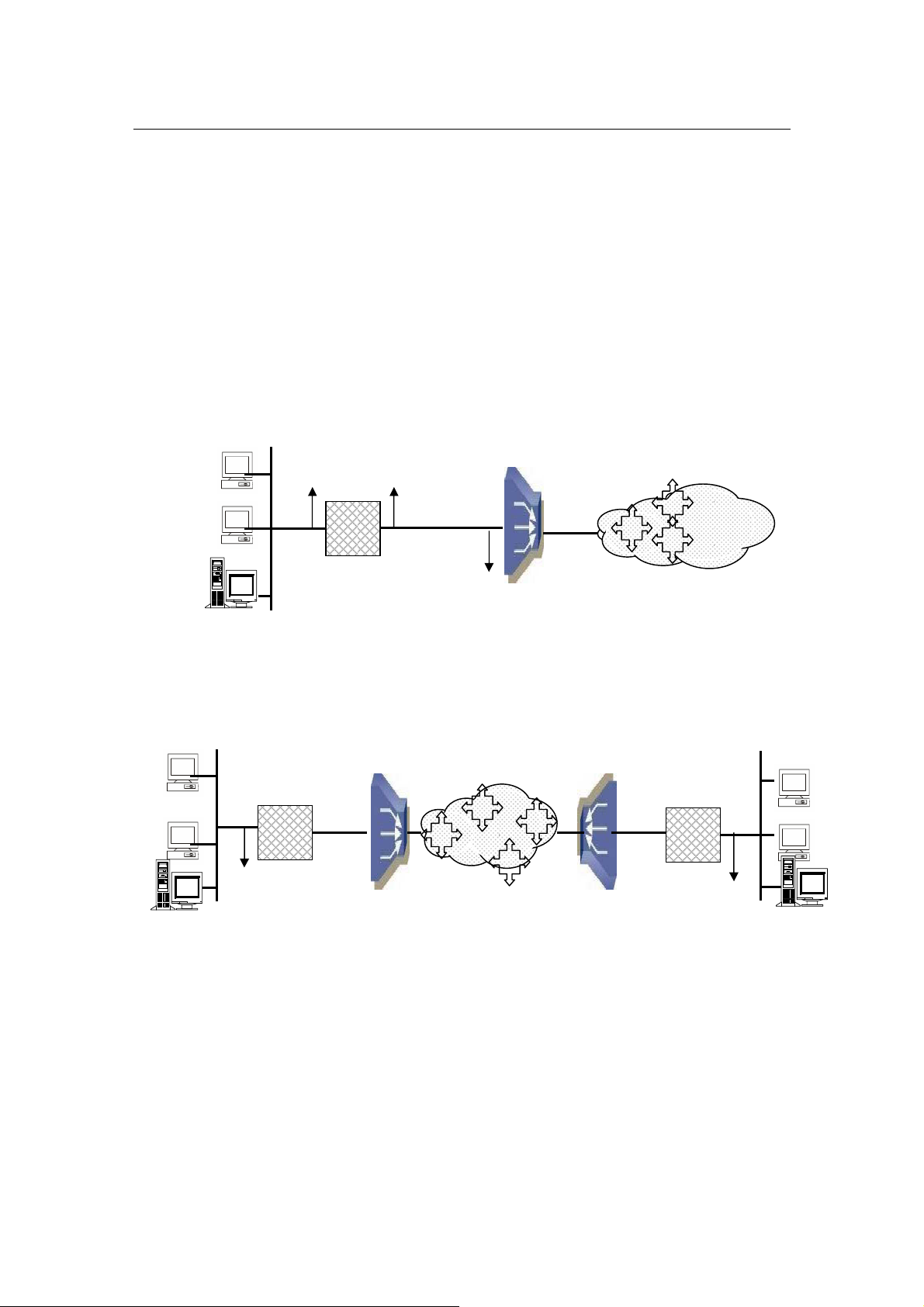
3.4.5 Router Mode
The operation mode of the system must set to ROUTER Mode. To change the mode,
please see the section 3.4.3. The following sections will help you to do configuration the
device in Router mode.
The application of the G.SHDSL Modem in Router Mode are illustrated in the following
figures
Corporation LAN
IP Address
IP Address
VPI/VCI
Corporation LAN
Figure 5: Router Mode - Application of AH507: Internet Access
IP Address
Figure 6: Router Mode - Application of AH507: LAN-to-LAN
AH507
IP Address
VPI/VCI
IP Address
Branch Office LAN
G.SHDSL Router - AH507 Version 1.0
25
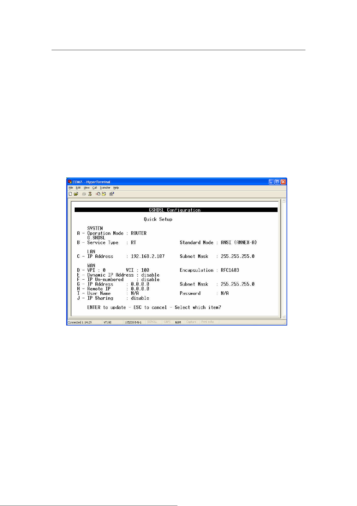
3.4.5.1 Quick Setup:
From Main Menu,
Press ‘B’ to open menu ‘Quick Setup’.
I Note: The WAN configuration is for the first Virtual Circuit (VC 1) in
twelve VC set available in the device

G.SHDSL Router - AH507 Version 1.0
26
The details of the items are described in the following table:
Item Field Name Description Value
A Operation Mode
B Service Type
Standard Mode
C LAN IP Address Local IP Address of router.
LAN IP Subnet
Mask
D VPI Virtual Path Identifier 0 – 16
VCI Virtual Channel Identifier 33 - 4096
System operation mode. Press ‘Space
Bar’ to select the setting.
System service type. System can be
operated as RT or COT type. Press
‘Space Bar’ to select the setting.
Physical standard mode. Press ‘Space
Bar’ to select the setting.
Local Subnet Mask of router.
BRIDGE / ROUTER
Default: BRIDGE
RT / COT
Default: RT
ETSI / ANSI
Default: ETSI
Default:
‘192.168.0.1’
Default:
‘255.255.255.0’
Encapsulation
Dynamic IP
E
Address
F IP Un-numbered Press ‘Space Bar’ to select the setting. Disable/Enable
G WAN IP Address
WAN IP Subnet
Mask
H Remote IP Address The IP Address of DSLAM, given by ISP i.e ‘229.122.79.32’
I User Name
Password
J IP Sharing
The encapsulation type is given by ISP.
Press ‘Space Bar’ to select the setting.
Press ‘Space Bar’ to select the setting.
The WAN local IP Address of router,
given by ISP
The WAN local IP subnet mask of router,
given by ISP
ISP login user name, given by ISP. It is
set for the encapsulation type of PPPoE
or PPPoA
ISP login password, given by ISP. It is
set for the encapsulation type of PPPoE
or PPPoA
IP Sharing or NAT (Network Access
Translation). Press ‘Space Bar’ to select
the settings.
RFC2684 / IPoA /
PPPoE / PPPoA
Default: RFC2684
Disable/Enable
Default: Disable
i.e ‘123.221.79.2’
i.e ‘255.0.0.0’
Max. 18 characters
Max. 18 characters
Disable / Enable
Default: Disable
G.SHDSL Router - AH507 Version 1.0
27
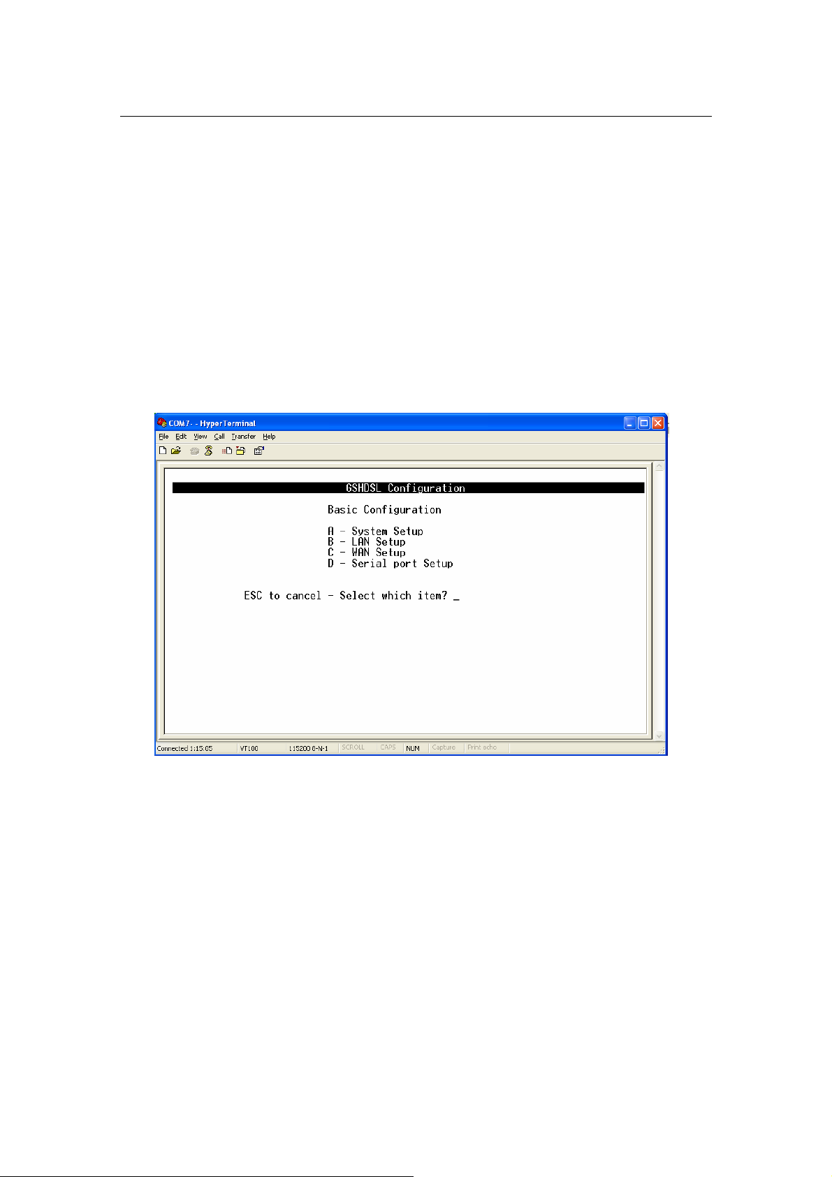
3.4.5.2 Basic Configuration:
From Main Menu,
Press ‘C’ to open menu ‘Basic Configuration
In menu Basic Configuration, the system can be configured in individual
submenu: System Setup, LAN Setup and WAN setup.
 Loading...